Titan Logix TPM 053 User manual

Tpm053001
Figure 1 –Titan Gateway
TITAN GATEWAY
INSTALLATION & OPERATION MANUAL
TPM 053
Version 1.0


TPM 053 Version 1.0, May 30, 2017 Page | 1
INTRODUCTION
Gateway Installation and Operation Manual
CUSTOMER SUPPORT
24 Hour Technical Support Line
1-877-462-4085
Titan Logix provides 24 hour technical support for their products. Call the technical support number:
•to arrange a service call
•if you have immediate questions regarding operations and installation
•if you have a request for documentation and/or software
•technical assistance
RETURNS FOR REPAIR,REPLACEMENT,OR CREDIT
Inside Sales (8:00-4:30 Mountain Daylight Time)
1-877-462-4085
NOTE
Returned product for repair, replacement, or credit, must be accompanied by a Titan
Logix generated RMA number.
To generate an RMA number:
1. Call the Inside Sales number to speak with a representative and obtain an RMA number
2. Provide the serial number of the item with a description of issue and expected resolution
3. Describe the issue and indicate whether the item is defective, missing components, not suitable
for the intended use, or purchased in error
4. Indicate the expected resolution (repair, replacement, return)
5. Return the item together with the RMA number to the indicated Titan service facility
When speaking with your Titan representative, please indicate whether the item is still under
warranty.
Shipping cost to and from a Titan Logix service facility is the responsibility of the customer unless the
product is under warranty. If the product is under warranty, the freight cost to Titan is incurred by the
customer. From Titan, the cost is incurred by Titan.
All returns for credit are subject to a 20% restocking fee.

TPM 053 Version 1.0, May 30, 2017 Page | 2
INTRODUCTION
Gateway Installation and Operation Manual
INTRODUCTION
This manual provides information specific to the Titan Gateway (hereafter referred to as the Gateway)
only.
This manual describes the operation and maintenance of the Gateway together with the TD80 and
Finch II systems. For complete installation and programming details on the TD80 Level Gauging System,
refer the TD80 product manual, TPM 001 and Finch II product manual, TPM 010.
Installation and operational information pertaining to optional equipment or peripheral systems will not
be included in this manual. Refer to the vendor supplied documents for more information.
This guide is intended to assist the user on the installation, use, and maintenance, of the Titan Gateway,
under normal working conditions. Operations outside the scope of this guide or specialized installations
will require further documentation. Please contact your nearest Titan Logix service facility with your
requirements.
It is essential that this manual be read and understood for proper installation and operation of your new
Gateway system.
WARRANTY
Please see our Terms and Conditions for details about our product warranty.
There are no serviceable parts in this device. A violated warranty seal will render any warranty null and
void.
DISCLAIMER
The information in this document is subject to change without notice. Titan Logix Corp. makes no
representations or warranties with respect to the contents hereof.
PROPRIETARY INFORMATION
The Information disclosed herein contains proprietary rights of Titan Logix Corp. Neither this document
nor the information disclosed herein shall be reproduced or transferred to other documents, or used or
disclosed to others for manufacturing purposes, or for any other purpose except as specifically
authorized in writing by Titan Logix Corp.
TPM 053 Version 1.0, May 30, 2017 Page | 3
INTRODUCTION
Gateway Installation and Operation Manual
SAFETY
The product must be installed and operated in accordance with Titan manuals, application notes, and all
other relevant publications. Only qualified personnel familiar with the installation and operation of this
equipment should install, adjust, operate, or service this equipment. Failure to observe this warning
could result in bodily injury or loss of life.
The Gateway system is not approved for use in hazardous locations. Do not operate, install, or repair the
system where flammable gasses and/or fumes may be present.
Observe all federal, state/provincial and local safety standards and industry recommended practices.
Turn vehicle power off before any installation or maintenance.
This manual will use the following standard safety terms and conventions to indicate conditions:
WARNING
Indicates a hazardous situation which, if not avoided, could result in death or serious
injury.
CAUTION
Indicates a hazardous situation which, if not avoided, could result in moderate injury
and/or property damage.
NOTE
Indicates an important message not related to personal injury or property damage.
Radio Frequency (RF) Safety
Notice regarding Compliance with FCC and Industry Canada Requirements for RF Exposure
The antenna intended for use with this unit meets the requirements for mobile operating configurations
and for fixed mounted operations, as defined in 2.1091 of the FCC rules for satisfying RF exposure
compliance.
Compliance of the device with the FCC and IC rules regarding RF Exposure was established and is given
with the maximum antenna gain as specified above for a minimum distance of 20 cm (8 in) between the
devices radiating structures (the antenna) and t e body of users.

TPM 053 Version 1.0, May 30, 2017 Page | 4
INTRODUCTION
GatewayTM Installation and Configuration Manual
SECURITY
Titan recommends the following steps to protect the security of your system:
•Change the Wi-Fi password from the factory setting
•Keep all passwords documented and secure. Password must use a combination of letters,
numbers, and symbols and be at least 8 characters long with no spaces or the special
characters: < > & ’

TPM 053 Version 1.0, May 30, 2017 Page | 5
INTRODUCTION
Gateway Installation and Operation Manual
CONTENTS
CUSTOMER SUPPORT.................................................................................................................................... 1
Returns for Repair, Replacement, or Credit ............................................................................................. 1
INTRODUCTION............................................................................................................................................. 2
Warranty ................................................................................................................................................... 2
Disclaimer.................................................................................................................................................. 2
Proprietary Information............................................................................................................................ 2
Safety ........................................................................................................................................................ 3
Radio Frequency (RF) Safety ................................................................................................................. 3
Security ..................................................................................................................................................... 4
TABLE OF FIGURES ........................................................................................................................................ 7
GATEWAY SYSTEM OVERVIEW ..................................................................................................................... 8
Gateway Components............................................................................................................................... 8
TD80 Components .................................................................................................................................... 9
Component Identification and Location .................................................................................................10
Features and Specifications ....................................................................................................................11
Features .............................................................................................................................................. 11
Specifications ......................................................................................................................................12
INSTALLING THE GATEWAY MODULE .........................................................................................................13
Pre-Installation........................................................................................................................................15
Mechanical Installation...........................................................................................................................16
Electrical Installation............................................................................................................................... 18
Confirming Gateway Module Operation ................................................................................................ 19
GATEWAY OPERATION................................................................................................................................ 20
GATEWAY UTILITY.......................................................................................................................................21
Overview .................................................................................................................................................21
Loading Utility Software..........................................................................................................................21
Gateway Utility Description ....................................................................................................................22
Gateway Status Screen ....................................................................................................................... 22
Connecting to the Network................................................................................................................. 22
Gateway Configuration Screen ...........................................................................................................23
Changing the Wi-Fi Password ............................................................................................................. 25
Configuration and Communication Test Procedure ............................................................................... 28

TPM 053 Version 1.0, May 30, 2017 Page | 6
INTRODUCTION
GatewayTM Installation and Configuration Manual
Updates................................................................................................................................................... 29
Security ................................................................................................................................................... 30
COMMISSIONING........................................................................................................................................31
TROUBLESHOOTING & MAINTENANCE ...................................................................................................... 32
Gateway Health Check............................................................................................................................ 32
Troubleshooting......................................................................................................................................33
Required tools and equipment ...........................................................................................................33
Optional tools and equipment (as required) ...................................................................................... 33
Gateway Troubleshooting................................................................................................................... 34
Gateway Communications Diagnostics...............................................................................................35
Gateway Communication Troubleshooting ........................................................................................ 37
Asset Management Dashboard Verification (3rd Party Provider) ...........................................................41
Repair...................................................................................................................................................... 41
TD80 and Finch II.................................................................................................................................41
Gateway Module.................................................................................................................................41
System Wiring ..................................................................................................................................... 41
Maintenance ...........................................................................................................................................41
REFERENCE DRAWINGS ..............................................................................................................................42
Tank Truck Wiring Schematic.................................................................................................................. 43
Trailer Wiring Schematic.........................................................................................................................45
Mounting Template Drilling Guide .........................................................................................................47

TPM 053 Version 1.0, May 30, 2017 Page | 7
INTRODUCTION
Gateway Installation and Operation Manual
TABLE OF FIGURES
Figure 1 –Titan Gateway .............................................................................................................................. 1
Figure 2 –Gateway Mounting Bracket ......................................................................................................... 8
Figure 3 –Gateway Module.......................................................................................................................... 8
Figure 4 –Interconnect Cable....................................................................................................................... 8
Figure 5 –Module Mounting Bolts ............................................................................................................... 8
Figure 6 –TD80 Transmitter ......................................................................................................................... 9
Figure 7 –TD80 Probe................................................................................................................................... 9
Figure 8 –Finch II Display.............................................................................................................................. 9
Figure 9 –Component Location..................................................................................................................10
Figure 10 –Gateway Module (Bottom View) ............................................................................................. 11
Figure 11 –Gateway Module (Top View) ................................................................................................... 11
Figure 12 –Inserting the Gateway.............................................................................................................. 17
Figure 13 –Gateway Identification Label ...................................................................................................21
Figure 14 –Truck Wiring Schematic............................................................................................................ 43
Figure 15 –Trailer Wiring Schematic ..........................................................................................................45
Figure 16 –Mounting Template ................................................................................................................. 47

TPM 053 Version 1.0, May 30, 2017 Page | 8
MODULE INSTALLATION
Gateway Installation and Operation Manual
Tpm053002
Tpm053003
Tpm053004
Figure 2 –Gateway Mounting
Bracket
Figure 3 –Gateway Module
Figure 4 –Interconnect Cable
GATEWAY SYSTEM OVERVIEW
The Titan Gateway is used to track your vehicle when in operation. The Gateway streams information on
vehicle speed, stops, and position as well as receiving system information from the TD80 Level Gauge
and Overfill Protection System. The Gateway uploads this information to a cloud-based server for data
tracking and analysis.
GATEWAY COMPONENTS
Gateway Mounting Bracket
The mounting bracket acts as a secure seat for the Gateway module. It is mounted to a
secure position on the vehicle and is to be installed as per the instructions provided in
this manual.
Gateway Module
The Gateway module wirelessly transmits position and motion information of the
vehicle, as well as gathering and transmitting data from the TD80 and Finch II
components. The module sits securely inside the mounting bracket and connects
directly to the TD80 and Finch II System via the Interconnect Cable.
Interconnect Cable
The interconnect cable is a wire cable that is supplied to connect the Gateway module to
the Finch II display through a third party junction box.
Module Mounting Bolts
The module mounting bolts are supplied in order to secure the Gateway module to the
mounting bracket.
Tpm053005
Figure 5 –Module Mounting
Bolts

TPM 053 Version 1.0, May 30, 2017 Page | 9
MODULE INSTALLATION
Gateway Installation and Operation Manual
Tpm053006
Tpm053007
Figure 6 –TD80 Transmitter
Tpm053008
Figure 7 –TD80
Probe
Figure 8 –Finch II Display
While the Gateway gathers and streams positioning data to the cloud, the TD80 and Finch II System
work together to display payload information. The TD80 and Finch II System are assumed to be in place
before installation of the Gateway.
TD80 COMPONENTS
TD80 Transmitter
The TD80 transmitter generates and processes the Guided Wave Radar signals to
determine liquid level in a tank. The TD80 is mounted on the tank top and connected to
the probe. TD80s are available in two versions, dual rod and coaxial probe for
compatibility with a wide range of liquids.
Probe
The probe guides the transmitted pulse and reflection from the surface of the liquid.
Probes are available in dual rod or coaxial versions and require a matching transmitter
type. The probe is mounted on the tank top and is connected to the bottom of the
transmitter. Dual rod probes are designed for viscous liquids. Coaxial probes are used
mostly for tanks containing products like aviation fuel.
Finch II Display
The Finch II Display is an external use, numeric display of volume information, alarms
and system error codes from the TD80 transmitter. Various alarm and error conditions
are detected by the transmitter and display. These alarm states control four internal
relays for alarm annunciation, high level shutdown and low level prevention.

TPM 053 Version 1.0, May 30, 2017 Page | 10
MODULE INSTALLATION
Gateway Installation and Operation Manual
COMPONENT IDENTIFICATION AND LOCATION
1001138v1.0
Figure 9 –Component Location
TPM 053 Version 1.0, May 30, 2017 Page | 11
MODULE INSTALLATION
Gateway Installation and Operation Manual
Tpm053009
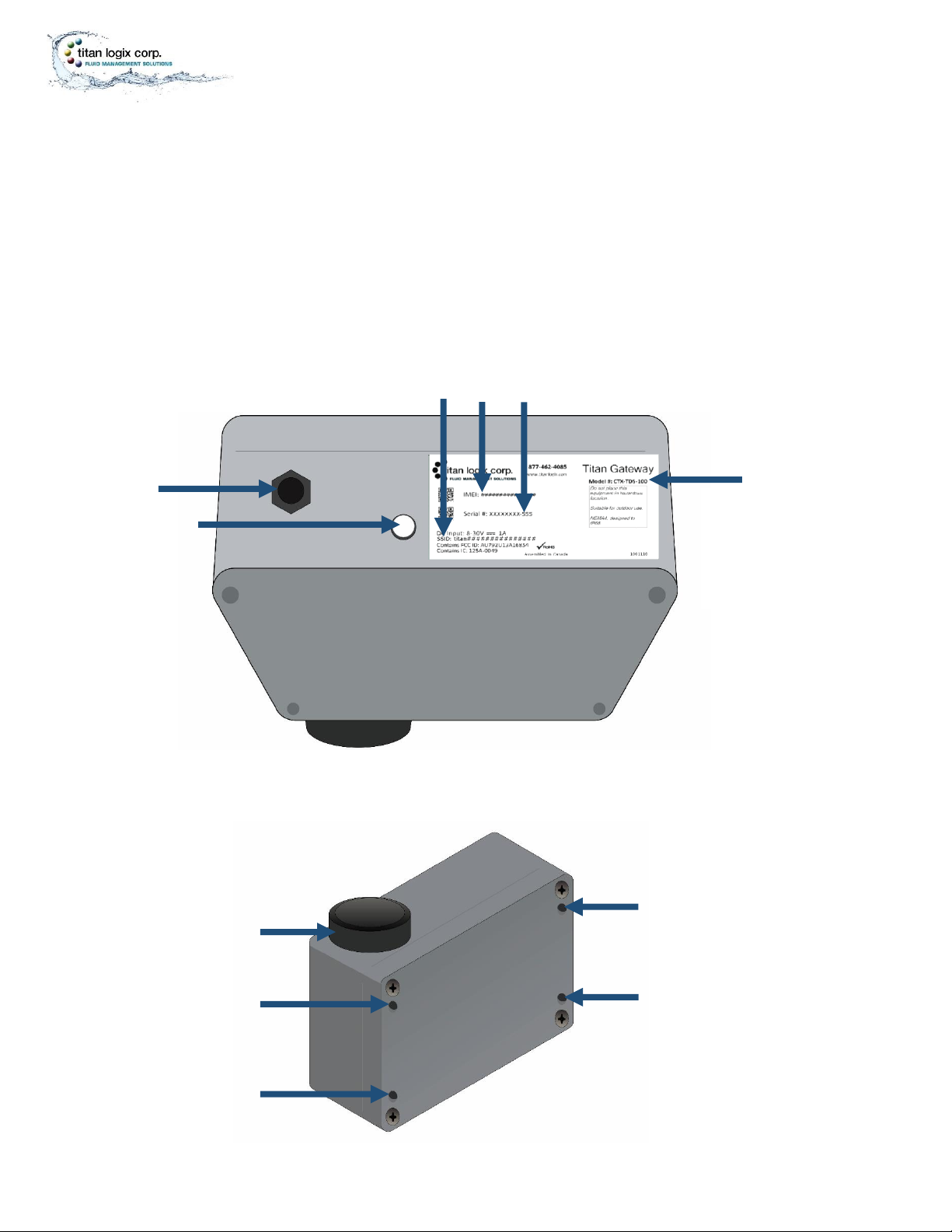
Figure 10 –Gateway Module (Bottom View)
Tpm053010
Figure 11 –Gateway Module (Top View)
FEATURES AND SPECIFICATIONS
Features
(viewed from the bottom of the Gateway module)
1. model number
2. serial number
3. IMEI
4. SSID
5. Interconnect Cable Connector
6. Status Light
(viewed from the top of the Gateway module)
7. Mounting holes (x4)
8. External antenna
❖

TPM 053 Version 1.0, May 30, 2017 Page | 12
MODULE INSTALLATION
Gateway Installation and Operation Manual
Specifications
1. Gateway Module
Physical Operating Temperature: -40C to +65C
Water and Dust Resistance: NEMA4 when Interconnect Cable is Connected
Corrosion Resistance: Fiberglass Reinforced Plastic (FRP) Enclosure
Mounting Bolt Torque Specification: 8-9.5 in.lb
Mounting Bolt Insertions: 4 times max.
Electrical Power: 8 –30VDC, 1A max.
Approvals Electrical Compliance: FCC and IC Class B Digital Device
Communication Serial: RS232
Cellular Radio: Supports HSPA+ and GPRS/EDGE
Wi-Fi: 802.11b/g/n 2.4GHz
Ethernet: 10/100 Base-T
2. Interconnect Cable
Water and Dust Resistance: IP66 when connected to Gateway Module
Physical Dimensions: 36’ +/- 12” (11m +/- 0.3m) length, 0.235” (6mm) O.D.
Material: UV Resistant, Black PVC, 4 X 20AWG stranded
3. Gateway Configuration Utility
Desktop or Laptop PC with Windows 7 or 10 Installed
Display resolution 1024 X 768 min.
Wi-Fi 802.11b/g/n, 2.4GHz
Optional Internal 10/100Base-T Ethernet Adapter
*External Ethernet adapter is not supported for Windows 10
Replacement Parts
Description
Titan Part Number
Gateway Mounting Bracket
1025-1042
Gateway Module, Model CTX-TDS-100
Gateway
Interconnect Cable
1003-0024
Mounting Bolts
1017-2112

TPM 053 Version 1.0, May 30, 2017 Page | 13
MODULE INSTALLATION
Gateway Installation and Operation Manual
INSTALLING THE GATEWAY MODULE
Prior to installation of the Gateway, verify that the TD80 system is operating normally and that the
Finch II firmware has been updated (version 1.07.00 or greater). Refer to the TD80 product manual,
TPM 001 and Finch II product manual, TPM 010.
For your convenience, we have provided a checklist so that you can keep track of where you are in the
installation process.

TPM 053 Version 1.0, May 30, 2017 Page | 14
MODULE INSTALLATION
Gateway Installation and Operation Manual
Pre-installation Checklist
Checked
Steps
1. Equipment Verified
•Required tools and equipment
•Optional tools and equipment
•Parts and material provided by Titan
•Parts and material not provided by Titan
2. Facility Requirements Verified
3. TD80 System Operation Confirmed
•Retrofit Installation
•New Installation
Mechanical Installation Checklist
Checked
Steps
1. Mounting Location Chosen
2. Mounting Bracket and Module Installed
3. Junction Box Installed
4. Air Pressure Switch Installed (Trailer)
5. Visual Inspection Performed
Electrical Installation Checklist
Checked
Steps
1. Power Supply Verified
2. Gateway to Junction Box Connected
3. Finch Display to the Junction Box Connected
4. Air Pressure Switch to Junction Box Connected (Trailer)
5. Electrical Power to Junction Box Connected
6. Visual Inspection Performed
Confirmation Checklist
Checked
Steps
1. Operation of the Gateway Confirmed

TPM 053 Version 1.0, May 30, 2017 Page | 15
MODULE INSTALLATION
Gateway Installation and Operation Manual
PRE-INSTALLATION
Verify Equipment
Required Tools
•Common automotive mechanical and electrical tools
•Power drill, drill bits
•Laptop PC
•Gateway Configuration software
Titan Supplied Parts
•Gateway Module
•Gateway Mounting Bracket
•Module Mounting Bolts
•Gateway Interconnect Cable
•Installation & Operation Manual TPM 053
•Configuration Utility Software and Manual TPM 054
•Quick Reference Sheet TPM 055
Vendor Supplied Parts
•Junction box kit - Truck - Litetm p/n 50400 or equivalent
•Compression fittings and filler plugs - Truck-Litetm or equivalent
oRecommended fitting for Gateway cable diameter, 0.235” (6mm) O.D.
•Insulated crimp or solder ring terminals
-Blue, 16 - 14 AWG, 8-10 Stud Size
-Red, 22 - 18 AWG, 8-10 Stud Size
•Multi-conductor trailer cable
-2 conductors, 16 - 14 AWG
-4 or 5 conductors, 16 - 14 AWG
o4 conductors for Gateway installation only
o5 conductors for Gateway and LoadMaxxtm installation
•Air pressure switch in a weatherproof enclosure for trailer installations
Verify Facility Requirements
Make sure that the installation area is in a weather protected area with adequate lighting, heating and
ventilation. Have battery/electrical power and compressed air (optional) available for tools and trailer
installation.
Confirm TD80 System Operation
Retrofit Installation
a. Confirm TD80 system operation according to Finch II product manual TPM 010, section 2.7 prior to
installing the Gateway.
b. Update Finch II firmware if required. Confirm Finch II firmware version for Gateway operation
(minimum version 1.07.00 or higher).
New Installation
a. After installation of the TD80 system and Gateway, confirm TD80 operation according to Finch II
product manual TPM 010, section 2.7.
TPM 053 Version 1.0, May 30, 2017 Page | 16
MODULE INSTALLATION
Gateway Installation and Operation Manual
b. Update Finch II firmware if required.
MECHANICAL INSTALLATION
WARNING
Ensure the tank is completely drained of liquid and vapour free.
No drilling or welding is to be performed on the tank and frame without first
consulting with the tank manufacturer.
CAUTION
•Ensure that the vehicle power is turned off before performing any other
work.
•Install the Gateway module in a non-hazardous location and use rated safety
equipment such as fall restraint, in accordance with facility regulations and
policies.
•Ensure fuses and components are appropriate for the area classification.
•Follow all federal, state/provincial and local safety standards and industry
recommended practices for the vehicle. For example, the Federal Motor
Vehicle Safety Standards (FMVSS) and the American Trucking Association
(ATA) Technology and Maintenance Council (TMC) Recommended Practices
(RP).
Choose the Mounting Location (Module and Junction Box)
•Choose a non-hazardous location
•Maximum view of sky for best radio reception (module only)
•Minimize electrical cable length where possible
•Locate for ease of installation and repair
•Protected from damage by road debris, trees, stepping or climbing, etc.

TPM 053 Version 1.0, May 30, 2017 Page | 17
MODULE INSTALLATION
Gateway Installation and Operation Manual
Refer to the Mounting Template Drilling Guide in the Reference Drawings section of this manual.
Install the Mounting Bracket and Module
a) Install the mounting bracket using the mounting template drilling guide.
b) Once the mounting bracket is bolted to the trailer, slide the module into the opening with the
antenna facing upwards and to the left when the unit is facing you.
c) Secure the module to the bracket with the bolts provided.
NOTE
Mounting bolts may only be inserted a maximum of four (4) times. Thread lock will
wear and cause loosening of the Gateway Module. Call Titan for replacement bolts.
Install the Junction Box
Install Air Pressure Switch for Trailer Installations
Perform a Visual Inspection
•ensure the area is free of debris
•ensure electrical connections are secure
•ensure all components are securely fastened
•ensure there is a clear view of sky
Tpm053011
Figure 12 –Inserting the Gateway

TPM 053 Version 1.0, May 30, 2017 Page | 18
MODULE INSTALLATION
Gateway Installation and Operation Manual
ELECTRICAL INSTALLATION
When installing the Gateway and other electrical components, the following guidelines must be
followed:
•Vehicle manufacturers usually have specific locations for electrical power access. These
locations are fuse protected to limit short-circuit current. Refer to the vehicle documentation or
contact the manufacturer for the recommended locations prior to the electrical installation.
•For trailers, connect the Gateway system power and ground to the nose box electrical
connector. This will be a fused electrical power source from the truck. For trucks, connect
system power to a switched and fused accessory power connection from the battery. A switched
electrical power source is required to reduce battery drain while not in operation.
•When making connections to the vehicle electrical ground, ensure that the wiring is terminated
at a battery ground terminal. Some metal components are electrically insulated from the battery
ground or bolted with painted surfaces causing a poor connection.
•Wire splices and interconnections should be made inside a weather proof enclosure or junction
box to prevent premature failure due to corrosion.
•Secure all wires and cabling with clips or cable ties.
•Tighten all compression fittings.
Refer to the Tank Truck/Trailer Wiring Schematics in the Reference Drawings section of this manual.
Verify the Power Supply
•Tank truck - Switched accessory power
•Tractor-trailer - Trailer ABS power or dedicated switched accessory power
The Gateway module must be supplied power while driving, to periodically report position and activity.
The Gateway is supplied by continuous power from a source that is energized when the key switch is
turned on.
On trucks, this is called ‘Accessory Power’. On trailers, it is typically supplied by the anti-lock braking
system (ABS) power from the J560 socket, pin-7.
Connect the Gateway to the Junction Box
a) Install the interconnect cable at the junction box and connect the free end into the 4-pin
connector at the bottom of the Gateway module, ensuring a fully seated connection
b) Ensure cables are secured
Refer to the electrical options above for truck or trailer installation.
Connect the Finch Display to the Junction Box
Connect the Air Pressure Switch to the Junction Box (Trailer Installations)
Connect Electrical Power to Junction Box
Perform a Visual Inspection
Table of contents
Other Titan Logix Gateway manuals

Popular Gateway manuals by other brands

bihl+Wiedemann
bihl+Wiedemann BWU3593 installation instructions

Baudcom
Baudcom BD-ONU-311RT user manual

Micro control systems
Micro control systems MCS-BMS-GATEWAY Communications manual

TANDBERG
TANDBERG D1320203 user guide

Thales
Thales Cinterion DGL61-W Hardware interface description

RTA
RTA 460PSMM-NNA4 Product user guide


