Titan SF16N-9 Installation manual

9 SPEED BENCH PILLAR DRILL SF16N-9
SAFETY AND OPERATING MANUAL

GUARANTEE
This product carries a Screwfix Direct Ltd guarantee of 12 months. If your product
develops a fault within this period, you should,in the first instance contact Screwfix
Direct Ltd on Freephone 0500 41 41 41. If the fault occurs within the first 12 months,
you may return the goods for a full refund or we will repair or replace the goods if
you prefer. When repair is not practical or identical goods are not available, alternative
goods of similar specification and quality will usually be provided but, failing this, you
will be offered a partial or full refund depending on the time period since purchase.
This guarantee specifically excludes losses caused due to:
- Fair wear and tear
- Misuse or abuse
- Lack of routine maintenance
- Failure of consumable items (such as batteries)
- Accidental damage
- Cosmetic damage
- Failure to follow manufacturer’s guidelines
- Loss of use of the goods
- Repairs attempted by anyone, unless authorized by Screwfix Direct Ltd.
This guarantee does not affect your statutory rights. This guarantee is only valid in the UK.
For further technical advice, spare parts or repair service (outside of guarantee) please
contact the customer helpline number on 0845 607 6380.
Congratulations on your purchase of a power tool from Screwfix Direct
Ltd. We want you to continue getting the best performance from it so this
handbook includes information on safety, handling and care. Please retain this
handbook in case you need to refer to any of the information in the future.
Your power tool comes with a 12-month guarantee,so should it develop
a fault within this period contact Screwfix Direct Ltd on Freephone 0500 41
41 41.

9 SPEED BENCH PILLAR DRILL SF16N-9
SAFETY INSTRUCTIONS
WARNING! Read all instructions. Failure to follow all instructions listed below
may result in electric shock, fire and/or serious injury.
SAVE THESE INSTRUCTIONS
1. Keep the work area clean.
Cluttered areas and benches invite injuries.
2. Consider work area environment.
Do not expose power tools to rain. Do not use power tools in damp or wet loca-
tions. Keep the work area well lit. Do not use tools in the presence of flammable
liquids or gases.
3. Guard against electric shock.
Avoid body contact with earthed or grounded surfaces (e.g. pipes, radiators,
ranges, refrigerators).
4. Keep persons away.
Do not let persons, especially children, not involved in the work touch the tool or
the extension cord and keep them away from the work area.
5. Store idle tools.
When not in use, tools should be stored in a dry, locked up place, out of reach of
children.
6. Do not force the tool.
It will do the job better and safer at the rate for which it was intended.
7. Use the right tool.
Do not force small tools to do the job of a heavy-duty tool. Do not use tools for
purposes not intended, for example, do not use circular saws to cut tree limbs or
logs.
8. Dress properly.
Do not wear loose clothing or jewellery, they can be caught in moving parts. Non-
skid footwear are recommended when working outdoors. Wear protective hair
covering to contain long hair.
9. Use protective equipment.
Use safety glasses. Use face or dust mask if working operations create dust.
10. Connect dust extraction equipment.
If the tool is provided for the connection of dust extraction and collecting equip-
ment, ensure these are connected and properly used.
11. Do not abuse the cord.
Never yank the tool to disconnect it from the socket. Keep the cord away from
heat, oil and sharp edges.
12. Secure work.
Where possible use clamps or a vice to hold the work. It is safer than using your
hand.
13. Do not overreach.
Keep proper footing and balance at all times.
14. Maintain tool with care.
Keep cutting tools sharp and clean for better and safer performance. Follow
instructions for lubrication and changing accessories. Inspect tool cord periodi-
cally and if damaged have them replaced by an authorised service facility. Inspect
extension cords periodically and replace if damaged. Keep handles dry, clean and
free of oil or grease.

15. Disconnect tools.
When not in use, before servicing and when changing accessories such as blades,
bits and cutters, disconnect tools from the power supply.
16. Remove adjusting keys and wrenches.
From the habit of checking to see that keys and adjusting wrenches are removed
from the tool before turning it on.
17. Avoid unintentional starting.
Ensure switch is in the “off” when plugging in.
18. Use outdoor extension leads.
When tool is used outdoors, use only extension cords intended for outdoor use
and so marked.
19. Stay alert.
Watch what you are doing. Use common sense. And do not operate tool when
you are tired.
20. Check damaged parts.
Before further use of the tool, it should be carefully checked to determine that it
will operate properly and perform its intended function. Check for alignment of
moving parts, binding of moving parts, breakage of parts, mounting and any other
conditions that may affect its operation. A guard or other part that is damaged
should be properly repaired or replaced by an authorised service centre unless
otherwise indicated in this instruction manual. Have defective switches replaced
by an authorised service centre. Do not use the tool if the switch dose not turn it
on and off.
21. Warning.
The using of any accessory or attachment other than those recommended in this
instruction manual may present a risk of personal injury.
22. Have your tools repaired by qualified person.
This electrical tool complies with the relevant safety rules. Repairs should only
be carried out by qualified persons using original spare parts, otherwise this may
result in considerable danger to the user.
HEALTH ADVICE
WARNING! When drilling, sanding, sawing or grinding, dust particles will be
produced. In some instances, depending on the materials you are working with,
this dust can be particularly harmful to you (e.g. lead from old gloss paint).
You are advised to consider the risks associated with the materials you are
workingwith and to reduce the risk of exposure. You should:
-- Work in a well-ventilated area.
-Work with approved safety equipment, such as those dust masks that are specially
designed to filter microscopic particles.
ADDITIONAL SAFETY INSTRUCTIONS FOR YOUR DRILL
PRESS
1. Only use lubricating oil on drill bits and not near to motor or electrical components.
Never spray as a cooling agent. A fatal electric shock could occur.
2. Always use sharp drill bits.

9 SPEED BENCH PILLAR DRILL SF16N-9
3. Never use sub-standard or blunt drill bits.
4. Never use excessive force on drill handle.
5. Always secure the workpiece to be drilled.
6. Always ensure the machine is securely mounted to a solid workbench.
7. Never remove the guard.
8. Always wear suitable gloves when handling swarf.
9. Wear suitable clothing. Adjust all loose clothing and remove ties, neck chains rings
and watches.
10. Tie long hair back or preferably wear a hair net.
11. Use correct speed for size of drill (see speed chart).
12. Care should be taken when drilling brass and copper as drill may jam and break if
to much pressure is applied.
Important note
Remove the mains plug from socket before carrying out any adjustment or servicing.
Ensure your mains supply voltage is the same as your tool rating plate voltage.

SYMBOLS
Read the manual Warning Wear gloves
Wear dust mask,eye & ear protection
Conforms to relevant safety standards

9 SPEED BENCH PILLAR DRILL SF16N-9
1. MACHINE BASE
2. PILLAR
3. FIXING SCREW
4. DRILL TABLE
5.CLAMPING SCREW
6. MACHINE HEAD
7. PULLEY COVER
8. MOTOR
9. GRIP KNOBS
10. KEY CHUCK
11. SPINDLE
Fig 1

ACCESSORIES
Chuck key: 1pc
Hexagon wrench: 3pcs
TECHNICAL DATA
Voltage:
Input power :
No load speed:
Chuck capacity:
Spindle taper:
Drilling capacity:
Drilling depth:
Table size :
Height:
Machine weight :
230V~50Hz
500W(S2:15mm)
280-2350min-1
Ø3 - Ø16
B16
Ø16
50mm
170 x170mm
620mm
21kg
12. MOUNTING HOLES
13. HINGED CHIP GUARD
14. DEPTH SCALE LOCK
15. TIGHTENING SCREW
16. PULLEY COVER LOCK SCREW
17. ON SWITCH
18. OFF SWITCH
19. HEAD LOCK SCREW
NOISE AND VIBRATION DATA
Sound pressure level: 61.5dB (A)
Sound power level: 74.5dB (A)

9 SPEED BENCH PILLAR DRILL SF16N-9
OPERATION INSTRUCTIONS
WARNING: Before using your drill
press,read the instruction manual
carefully.
1.UNPACKING YOUR MACHINE
Carefully unpack all the content and lay them
out on the floor. Check contents against check
list below. Retain packaging until all parts are
accounted for and assembly has been complete.
Lift out base plate and remove protective paper
and place on workbench.
Inside the small box you will find the chuck,
three handles, three set bolts, three washers,
two hexagonal keys and chuck key. Place on
workbench.
Lift worktable out and remove protective paper.
Put on workbench. Remove headstock and motor
assembly and put on workbench. Remove column
and plastic guard. Put plastic guard away for time
being.
2.ASSEMBLY (See Fig 1-3)
Assemble the machine as follows:
- Position the machine base (1).
- Fasten the pillar (2) to machine base (1) using
three screws (3) and washers.
- Push the drill table (4) onto the pillar (2) (fig 3).
- Lock the drill table into the desired position
using the clamping screw (5).
- Place the drill head (6) with pulley cover (7) and
motor (8) onto the pillar and fasten using the
head lock screw (19).
- Screw the three grip knobs (9) onto the feeder
cross handle.
Note: All bare parts are greased in order to
protect them from corrosion. Before mounting
the drill chuck (10) onto the spindle (11), both
parts must be completely degreased using an
environmentally friendly solvent. This ensures
optimal transmission of power.
- Mount the drill chuck onto the spindle.
3.INSTALLING THE MACHINE (See Fig 3)
Before the drill is started for the first time, it must
be solidly and fully mounted on the work area
of a stable workbench. Select suitable length
bolts, washers and nuts (not supplied). Use four
mounting holes (12) in the base plate to do this.
Ensure that the machine is freely accessible for
Fig 2
Fig 3

operation, adjustment and maintenance.
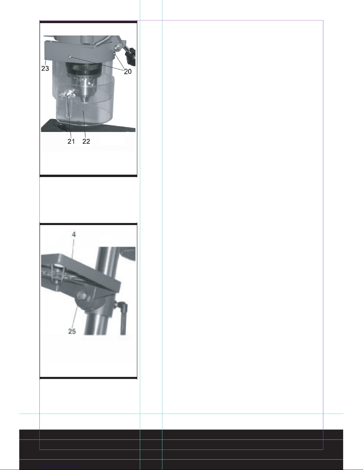
Note: The fixing screws may only be tightened
to a point where they do not distort or deform
the base plate. Excessive tension can lead to
fracture.
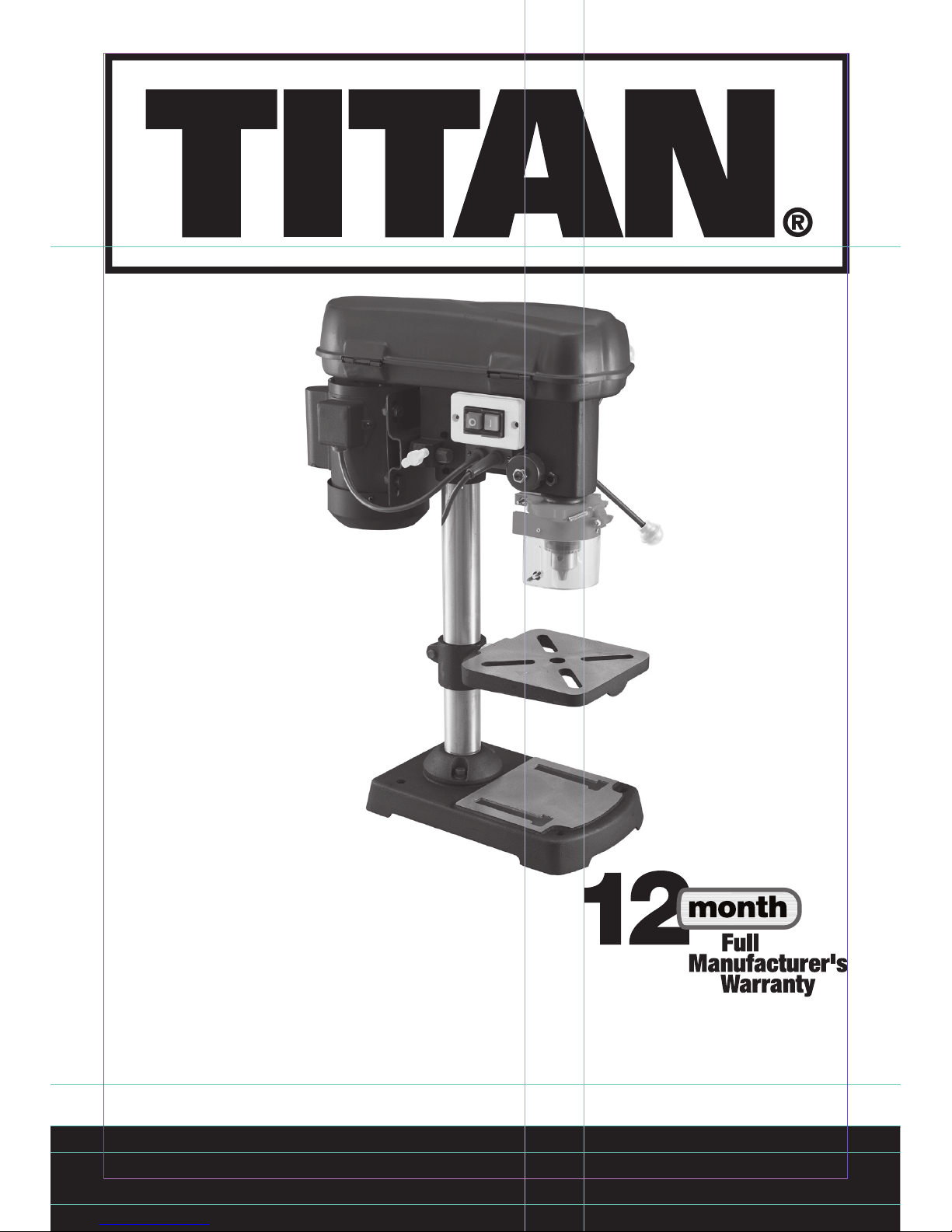
4.HINGED CHIP GUARD (See Fig 4)
Unscrew the three-recessed head screws (20).
Push the transparent cover (22) into the groove of
the red mounting frame (23) and fasten it again
with the recessed head screws (20).
The height of the cover (22) is infinitely adjustable
and can be locked using the two thumb screws
(21).
The chip guard (13) can be flipped upwards to
change drill bits; ensure, however, that the chip
guard (13) is back in its initial position before
restarting the machine.
5.PRIOR TO STARTING
Ensure that the voltage of the mains supply
complies with the specifications on the rating
plate. Connect the machine only to a socket with
the properly installed earthing contact.The table
drill is equipped with a no-volt trip that is designed
to protect the operator from an undesired restart
following a drop in voltage. Should this occur, the
machine must be manually restarted.
6.OPERATION GENERAL (See Fig 2)
To switch on the machine, push in the green On
button “l” (17); the machine starts up. To switch
off, press the red Off button “o” (18); the device
shuts down. Ensure that you do not overload the
device. If the sound of the motor drops in pitch
during operation, it is being overloaded. Do not
overload the device to the point where the motor
comes to a standstill.
The machine is designed for continuous operation
with intermittent load (S2 :15 min).
The machine may be operated under a full load
for a maximum of 15 minutes, at which time
the machine needs to idle for 15 minutes. This
prevents the motor from overheating.
7.INSERTING THE TOOL (See Fig 1)
Make sure that the power plug is removed from
the socket-outlet before changing tools. Only
cylindrical tools with the stipulated maximum
shaft diameter may be clamped in the scroll
Fig 4
Fig 5

9 SPEED BENCH PILLAR DRILL SF16N-9
chuck (10). Only use a tool that is sharp and
free of defects. Do not use tools whose shaft is
damaged or which are deformed or flawed in any
other way. Use only accessories and attachments
that are specified in the operating instructions or
have been approved by the manufacturer.
8.HANDLING THE DRILL CHUCK (See Fig 1)
Your table drill is equipped with a key chuck (10).
In order to insert a drill bit, flip up the chip guard
(13), insert the drill bit, then tighten down the drill
chuckusing the supplied chuck key.
Pull out the chuck key. Ensure that the clamped in
tool is firmly seated.
Caution! Do not leave the chuck key in the clamp
hole. Doing so will cause it to shoot out, which
could cause injury.
9.SETTING THE SPEED (See Fig 1, 6, 7)
First switch the machine off, then pull out the
mains plug.
The various spindle speeds can be set by moving
the V-belt.
Proceed as follows:
- Remove the screw (16) in order to open the
pulley cover (7).
- Slacken the tightening screw (15) and push the
motor (8) in the direction of the machine head.
- Move the V-belt to the desired position.
- Refer to the table for the recommended speeds
for different drill bit materials (fig 6).
- Tighten the V-belt by pushing the motor (8) back
from the machine head (6). Screw the tightening
screw (15) back down again. The tension is
properly set when the V-belt flexes in the middle
by approx. 1 cm when pressed.
- Close the pulley cover and screw down using
the screw (16).
The pulley cover (7) must always be locked tight,
as the machine is equipped with a safety switch
that only allows the machine to be turned on
when the pulley cover (7) is closed.
Caution! Never let the pillar drill run when the
pulley cover is open. Always pull the mains plug
before opening the cover. Never touch the V-belt
when it is rotating.
10.DRILL DEPTH STOP POINT (See Fig 8)
The drilling spindle has a swiveling scale ring
for setting the drill depth. Only adjust the setting
Fig 6
Fig 7
position position position

when the machine is at a standstill.
-Lower the drilling spindle (11) until the tip of the
drill bit touches the workpiece.
-Slacken the depth scale lock (14) and turn the
scale ring (24) forwards until it stops.
-Turn the scale ring (24) back to the desired drill
depth, then lock this setting into place using the
depth scale lock (14).
11.SETTING THE ANGLE OF THE DRILL
TABLE (See Fig 5)
- Slacken the carriage bolt (25) under the drill
table (4).
- Set the drill table (4) to the desired angle (which
can be read off the scale on the top side of the
drill table).
- Tighten down the carriage bolt (25) in order to
lock the drill table (4) into this position.
12.SETTING THE HEIGHT OF THE DRILL
TABLE (See Fig 1)
- Slacken the tightening screw (5).
- Set the drill table (4) to the desired height by
pressing down or lifting up and simultaneously
(gently) pushing to the left or right.
-Screw the tightening screw (5) back down again.
13.NEVER HOLD THE WORKPIECE IN PLACE
WITH YOUR HAND!
When drilling you must ensure that the workpiece
can move freely in all directions .This will allow
you to precisely locate the drill bits.
Always ensure that the workpiece cannot rotate.
Caution! Sheet metal parts have a tendency
to “snatch” (rise up the dill bit) suddenly
unexpectedly always. Ensure workpiece is securly
clamped before drilling.
There must be enough distance (>10mm) between
the upper edge of the workpiece and the tip of the
drill bit.
14.COUNTERSINKING AND CENTER-
DRILLING
With this table drill, you can also countersink and
center-drill. Please observe that countersinking
should be performed at the lowest speed, while a
high speed is required for center-drilling.
15.CARE AND MAINTENANCE
The table drill is to a large extent maintenance-
Fig 8
Fig 9

9 SPEED BENCH PILLAR DRILL SF16N-9
free.
Keep the device clean.
Pull out the mains plug before doing any cleaning
and maintenance work on the machine.
Do not use any harsh, abrasive cleaning
solvents.
Ensure that no liquid seeps into the device.
Re-gress all bare parts when the work is finished.
The drill pillar, blank parts of the column, and
the drill table especially should be regressed
at regular intervals. Use standard, acid-free
lubricating grease to do this.
Regularly check and clean the ventilation holes.
Store the device in a dry room. Should the
device become damaged, do not try to repair it
yourself; leave this work to a qualified electrical
technician.
16.ASSEMBLY OF THE CHUCK
Holding the chuck on the spindle, tap with a block
of wood hammer or a soft tip hammer to set the
chuck onto the spindle. (See fig9)
17.DISASSEMBLY OF THE CHUCK
Disconnect the bench drill from the power supply.
Fit a suitable length bolt through the work table
hole, do not tighten it (See fig10).
Adjust the work table to a suitable height and lock
the work table. Move down chuck and tighten the
chuck onto the bolt (See fig11 & 12). Turn handle,
move up spindle. Chuck will be pulled off.
Fig10
Fig 11&12

MAINTENANCE
Always lubricate drill bits with suitable oil when
drilling.
This will prolong the life of drill bits.
Caution: Do not use water-based coolant or
any kind of continuous coolant pump.
Remove all swarf and dust after each operation.
Spread oil onto unplated surfaces especially if
the machine is not used for long periods.
Lubricate the Spindle drive with oil every six
months.
Spindle guide screw should be checked
periodically to finger tightness.
ENVIRONMENTAL PROTECTION
Waste electrical products should not be
disposed of with household waste. Please
recycle where facilities exist. Check with
your Local Authority or retailer for recycling
advice.
Drilling Speed Chart (Guide Only)
Material to be drilled
Steel Cast Iron Hard Metal Aluminium Plastic Wood
Drill
mm Drill speed (min-1)
3 2350 2350 1550 2350 2350 2350
4 1700 2350 870 2350 2350 2350
5 1700 1700 870 1700 2350 2350
6 1550 1700 720 1700 2350 2350
7 870 1550 720 1550 2350 2350
8 720 870 620 1550 2350 2350
9 620 720 540 870 2350 2350
10 620 720 540 870 2350 2350
11 540 620 450 720 2350 1700
12 540 620 450 720 2350 1700
13 450 540 450 620 1700 1700
14 450 540 280 620 1700 1550
15 280 450 280 540 1550 1550
16 280 450 280 540 1550 1550

9 SPEED BENCH PILLAR DRILL SF16N-9
PLUG REPLACEMENT
The fuse in the main plug of your power tool
should always be replaced with one of identical
rating.
Check the voltage given on your power tool
matches the supply voltage.
The power tool is supplied with a fitted plug,
however if you should need to fit a new plug
follows the instruction below.
IMPORTANT
The wire in the mains lead are coloured in
accordance with the following code:
Green & yellow ---Earth
Blue ---Neutral
Brown ---Live
The wire which is coloured green & yellow must
be connected to the terminal which is marked
with E or .
The wire that is coloured blue must be connected
to the terminal that is marked with the letter N.
The wire that is coloured brown must be
connected to the terminal that is marked with the
letter L.
A 13AMP (BS1363 or BS1363/A) plug must be
used and a 5 AMP fuse must be fitted.

Declaration of Conformity
We, Importer
Screwfix Direct Ltd
Mead Avenue
Houndstone Business Park
Yeovil
BA 22 8RT
Declare that the product
9 SPEED BENCH PILLAR DRILL
SF16N-9
Complies with the essential health and safety requirements of the following directives:
89/336/EEC, 93/68/EEC–EMC Directive.
73/23/EEC, 93/68/EEC–Low Voltage Directive
98/37/EC–Machinery Directive.
Standards and technical specifications referred to:
EN 61029-1:2000
EN 55014-1 /A2:2002
EN 55014-2 /A1:2001
EN 61000-3-2:2000
EN 61000-3-3: /A1:2001
Authorised Signatory
Date: 15/09/05
Signature:
Name: Peter Harries
Screwfix Direct Ltd
Quality Manager
2005

Table of contents
Other Titan Drill manuals

Titan
Titan TTD129COM Installation manual

Titan
Titan TTB276DRL Installation manual

Titan
Titan TTI270COM Maintenance and service guide

Titan
Titan TTB085DRL Installation manual

Titan
Titan TTB877DRH User manual

Titan
Titan TTI526COM Installation manual

Titan
Titan TTI871SDS User manual

Titan
Titan TTB541DBT User manual

Titan
Titan TTP451DDH User manual

Titan
Titan TTD127DDH Installation manual