Titus THRC High Flow User manual

Redefine your comfort zone. ™ | www.titus-hvac.com
INSTALLATION &
OPERATION MANUAL
Titus HEPA Room Cleaner
High Flow & Low Flow Configurations

2
IOM - THRC Redefine your comfort zone. ™ | www.titus-hvac.com
IOM
THRC HF & LF
Table of Contents
Introduction....................................................................................................................... 3
Installation ........................................................................................................................ 4
Operation.......................................................................................................................... 5
Maintenance & Service..................................................................................................... 7
Troubleshooting................................................................................................................10
Wiring Diagram................................................................................................................ 11
Specifications .................................................................................................................. 13
Replacement Parts.......................................................................................................... 14
Airow Measurement & Testing ....................................................................................... 16

3
IOM - THRC
Redefine your comfort zone. ™ | www.titus-hvac.com
■Introduction
Description
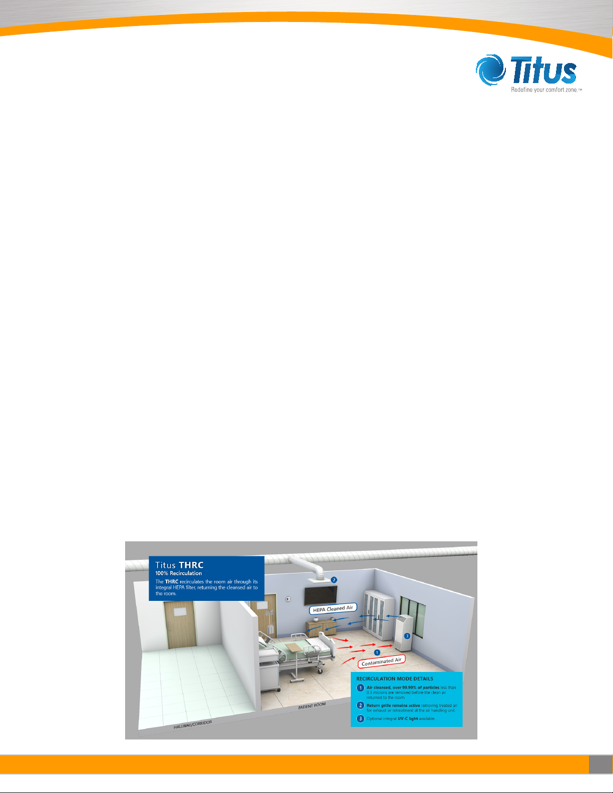
The THRC is a portable, self-contained high efficiency particulate air (HEPA) filtration system with an optional
ultraviolet lamp that helps to disinfect the filter face. The THRC is designed to easily and economically create a negative
pressure isolation room that will meet OSHA and CDC TB guidelines. The THRC can be used as a positive pressure clean
air recirculating system in clinics, waiting rooms, hospital emergency rooms and other confined areas or as a partial or
complete exhausting system to create a negative pressure isolation room for possible use with patients known or
suspected of having TB, SARS, COVID-19, or other infectious diseases. The THRC is available in two different sizes: the
THRC Low Flow (LF) and the THRC High Flow (HF). As a recirculating unit, the THRC’s powerful motor/blower can deliver
up to 370 CFM (628 m3/hr) for the THRC LF and up to 800 CFM (1360 m3/hr) for the THRC HF to provide a large number
of room air changes per hour to minimize the spread of airborne diseases to patients and health care workers. As a
negative pressure unit, the air passing through the HEPA filter is filtered of 99.99% of particles at 0.3 micron and may be
exhausted directly to the exterior through a window, or through a wall, simply by connecting flexible ducting to the 6 in. (152
mm) collar located on the top of the THRC.
Features
• Low Cost Isolation Room
The THRC is an easy and economical solution for creating a negative pressure isolation room. Simply roll the
THRC into a standard room, connect flexible ducting to the 6 in. (152 mm) collar on the top of the unit for partial
exhaust or to the optional 8 in. (204 mm) flanged collar for total exhaust, and vent the purified air to the exterior through
a window or wall.
• Flexible Applications
The versatile THRC can be used as a clean air recirculating unit, a negative pressure unit, or as a split system to
create both negative pressure and clean air recirculation by simultaneously exhausting some of the air out while
recirculating the remainder back into the room.
• Small and Portable
The THRC can be rolled from one room to another and easily fits into areas with limited floor space.
• Simple Maintenance
Both HEPA filter and prefilter are easily accessible for replacement by authorized personnel.
•Adjustable Airflow
The THRC provides effective air filtration for a wide variety of room sizes. The THRC LF utilizes a solid state speed
control with airflows ranging from 70 to 370 CFM (118 to 628 m3/hr). The THRC HF utilizes a three position switch with
airflows ranging from 560 to 800 CFM (951 to 1360 m3/hr).
• Low-High Clean Air Circulation Pattern
Room air, along with airborne contaminants, is drawn into the intake grill at the bottom while the purified air is discharged
at a high velocity from the exhaust grill located at the top of the THRC to generate a sweeping, low-to-high air
circulation pattern with adequate “reach” to optimize the clean breathing zone for patient and staff.
• Quiet Operation
Applications
Hospital
• Negative Pressure Rooms
• Emergency Rooms
• Waiting Rooms
• Sputum Induction
•Aerosol Pentamidine Treatment
• Intensive Care Units
•Bronchoscopy Rooms
• Renal Dialysis Rooms

4
IOM - THRC Redefine your comfort zone. ™ | www.titus-hvac.com
IOM
THRC HF & LF
Other
• Clinics
•Physician Oces
• Correctional Facilities
• Nursing Homes
• Homeless Shelters
• Addiction Recovery Center
Options
•THRC with UV
•THRC with ULPA Filter Upgrade
•220 V, 50/60 Hz Unit Available
•8 in. (203 mm) 100% Exhaust Collar Kit
■Installation
Unpacking Instructions
1. The THRC is shipped in an open-framed crate. The module
should be inspected for exterior shipping damage immediately
upon arrival. If any damage is observed, a claims report
should be completed and promptly filed with the responsible
carrier.
2. Uncrate and remove all packing material. Examine the unit for
internal damage. lf damage is discovered inside the crating, file
a claim with the responsible carrier immediately. The shipping
components list and actual material received should be compared and any shortages reported to Titus immediately.
Assembly
1. The THRC is shipped completely assembled from the factory and requires no assembly. Every unit is tested prior to
shipment to verify airflow and that the unit is leak-free.
2. Place the unit in its final operating position.
3. Lock the wheel locks on the casters to keep the unit from accidental repositioning.
Initial Start-Up
NOTE:THECDCREQUIRESTHATQUANTITATIVELEAKAGEANDFILTERPERFORMANCETESTSBEPERFORMED
AT THE INITIAL INSTALLATION AND EVERY TIME THE FILTER IS CHANGED OR MOVED. TESTS SHOULD BE
REPEATEDEVERYSIXMONTHSORTHEAPPROPRIATETIMEFRAMETHATISREQUIREDFORTHEAPPLICATION.
THE FACTORY TESTS SHOULD NOT BE SUBSTITUTED FOR THE INITIAL TEST.
CAUTION AND WARNINGS
READ AND SAVE THESE INSTRUCTIONS
WARNING: To reduce the risk of re, electrical
shock, or injury to persons, observe the following.
1. Installation work and electrical wiring
must be done by a qualied person(s)
in accordance with all applicable codes
and standards, including re-rated
construction.
2. Service to this equipment should be
performed by an authorized technician
trained and experienced in performance
evaluation and maintenance of clean air
equipment.
3. Before servicing or cleaning unit, unplug
the unit power cord from outlet to
prevent power from being switched on
accidentally.
4. This unit may have UV lamps. Eye
damage may result from direct exposure
to the light. Take UV radiation protective
measures for personnel during service.
5. Use this unit only in the manner intended
by the manufacturer.
5
IOM - THRC
Redefine your comfort zone. ™ | www.titus-hvac.com
■Operation
Initial Start-Up
1. Connect the power cord to a standard 115-Volt, Single Phase, 60 Hertz, or 220-Volt, 50/60 Hertz, grounded power source.
Verify that the circuit is sized to provide sufficient amperage as noted on the THRC data plate.
2. Locate the “ON/OFF” switch on the right side of the unit. The switch is a maintain contact rocker type.
3. Turn the THRC unit on by pressing downward on the raised portion of the rocker switch. A light whirring sound will be
heard as the motor starts. Within 5 to 10 seconds, the module will start to provide clean air into the environment.
Speed Adjustment
Note: THRC HF unitsare set on high speed at the factory. TLRC LF units are set to OFF.
1. To change speeds, remove the supply grille by pulling down and lifting out.
2. Turn the 3-speed switch (or solid state speed control) to the desired setting on the THRC HF or LF.
3. Replace the supply grille when finished.
Filter Change Indicator
1. Locate the airflow indicator on the right side of the unit above the “ON/OFF” switch. On high speed, the light will turn on
when there is insufficient pressure, indicating the need for a filter change. It is recommended to change prefilter. If the
filter change indicator light is still illuminated, it is recommended to replace the HEPA filter. The airflow indicator should
not be used as the only guide for when a filter change is necessary. The unit should be checked at each use to ensure
recommended room air changes per hour are being met.
2. The filter change indicator light can be adjusted by adjusting the pressure switch which can be seen on the back panel of
the THRC. For setting the light, block the lower intake grill approximately 75% while the unit is on high speed. The
pressure switch should be set to have the light flicker while covered 75%. Once the restriction is removed, the light should
go off. If the intake grille is completely covered, the light should be solid on.
3. The air velocity generated by the unit may be checked using an airflow measurement device. For the THRC HF the
volume of air entering the lower intake grille should be approximately 560 CFM (951 m3/h) on low, 690 CFM (1172
m3/h) on medium, and 800 CFM (1359 m3/h) on high with a new filter. Air volume on the THRC LF should be
approximately 70 CFM (118 m3/h) to 370 CFM (628 m3/h) depending on the position of the speed control with a new filter.
Recirculation Mode
1. The THRC unit is set at the factory on the 100% air recirculation mode.
2. The room air change rate of the unit will depend on both the THRC speed setting and the size of the room.
3. For maximum recirculation efficiency in a patient room, the unit should be placed between the entry door and the patient’s
bed or the activity area (see Figure 1 below). However, the unit will function effectively at other locations within the room.

6
IOM - THRC Redefine your comfort zone. ™ | www.titus-hvac.com
IOM
THRC HF & LF
Partial Exhaust/Recirculation Mode
Note: The THRC units come with a removable Exhaust Cover Plate and a removable 6-inch (152mm) Duct Collar for
attachment to exhaust ducting (not included) to create a negative pressure room. lf the Exhaust Cover Plate is not
removed, the THRC units will operate in the 100% recirculation mode.
1. Remove the Exhaust Cover Plate located on top of the lsoClean® unit by taking off the four (4) screws and plastic caps
used to secure the cover to the THRC exhaust port.
2. Remove the 6-inch (152mm) duct collar underneath the top cover and flip the collar over.
3. Attach exhaust ducting (not included) onto the collar and fasten tightly with a round hose clamp (not included).
4. Mount the duct collar with ducting onto the THRC exhaust port using the four (4) screws that originally held the cover
plate. Note: Keep the top plate and plastic washers for re-assembly when needed.
5. The HEPA filtered exhaust air can now be vented to the outside or returned to the main HVAC system1. lf the unit is ducted
to an exhaust duct rather than directly to the outside, it must be verified that the exhaust duct is capable of handling the
exhaust air expelled by the unit.
6. The lTHRC is designed to exhaust 100-300 CFM for the High Flow and 25-150 CFM for the Low Flow at the 6-inch
exhaust port. lt is recommended that the unit be set on the high-speed setting when operating in this mode to achieve
maximum exhaust and negative pressure. At this setting, the THRC will exhaust approximately 300 CFM (510 m3/h) and
recirculate 500 CFM (850 m3/h) for the High Flow and exhaust approximately 150 CFM (254 m3/h) and recirculate 220
CFM (373 m3/h) for the Low Flow.
Total Exhaust Mode (Negative Pressure)
CAUTION: To reduce risk of re and to properly exhaust air, be sure to duct air outside - Do not vent exhaust air into
spaces within walls or ceilings or into attics, crawl spaces, or garages.
CAUTION: For General Ventilating Use Only. Do Not Use to Exhaust Hazardous or Explosive Materials and Vapors.
Note: The cover plate must be securely attached to the top of the THRC for the unit to run in the 100% exhaust mode.
An optional 8-inch (203mm) Exhaust Collar with Flange is available to convert the THRC unit to the 100% exhaust mode.
1. Remove the front exhaust grille by pulling down and lifting out.
2. Place the optional 8-inch (203mm) exhaust collar over the opening where the grille was removed and attach with the
screws included with the 8-inch collar.
3. Attach exible exhaust duct (not included) over the 8-inch collar and fasten tightly with a round hose clamp (not included).
4. The HEPA ltered exhaust air can now be vented to the outside or returned to the main HVAC system1. lf the unit is ducted
to an exhaust duct rather than directly to the outside, it must be veried that the exhaust duct is capable of handling the
exhaust air expelled by the unit.
Negative Pressure
NOTE: CDC GUIDELINES RECOMMEND THAT ROOMS USED FOR NEGATIVE PRESSURE ISOLATION SHOULD
BE SINGLE PATIENT ROOMS WITH NEGATIVE PRESSURE RELATIVE TO THE CORRIDOR OR OTHER AREAS
CONNECTED TO THE ROOM. THE MINIMUM PRESSURE DIFFERENCE NECESSARY TOACHIEVE AND MAINTAIN
NEGATIVE PRESSURE THAT WILL RESULT IN AIRFLOW INTO THE ROOM IS 0.01 INCH W.G. (2.5PA) (A HIGHER
PRESSURE IS PREFERRED). TO ACHIEVE THIS, THE EXHAUST FLOW SHOULD BE 10% OR 50 CFM (85 M3/H)
GREATER THAN THE SUPPLY (WHICHEVER IS GREATER).
Achieving Negative Pressure
1. The THRC unit is designed to exhaust 100-300 CFM (High Flow unit) or 25-150 CFM (Low Flow unit) when the 6-inch
(152.4mm) exhaust collar is used. lt is recommended that the unit be set on the high-speed setting when operating in
this mode to achieve maximum exhaust and negative pressure.
2. lf an exhaust volume greater than 300 CFM (800 unit) or 150 CFM (400 unit) is required to create a negative pressure
room, the optional 8-inch (203.2 mm) 100% exhaust collar should be used.
3. The attachment of ductwork to the exhaust port decreases the air volume exhausted through the port. The magnitude of the
decrease varies depending on the length and type of duct as well as unit configuration.
1 CDC recommends that air from negative pressure rooms be exhausted to the outside in accordance with federal, state, local or country regulations.
The air should not be recirculated into the general ventilation. ln certain cases in existing facilities, recirculation of air into the general ventilation system
is unavoidable and, in such cases, CDC guidelines state that HEPA lters should be installed in the exhaust duct leading from the room to the general
ventilation system.
7
IOM - THRC
Redefine your comfort zone. ™ | www.titus-hvac.com
NOTE: IT IS THE RESPONSIBILITY OF THE PURCHASER, AND NOT Titus, TO ENSURE THE ROOM IN WHICH
THE UNIT IS USED IS IN COMPLIANCE WITH CDC GUIDELINES2FOR ANEGATIVE PRESSURE ISOLATION
ROOM AND MONITORED TO ENSURE ITS CONTINUING PERFORMANCE.
Difficulty Achieving Negative Pressure
The equipment may not be able to achieve or maintain negative pressure in conformance with the CDC Guidelines2due
to building ventilation of rooms or air leakage. The room should be inspected for air leakage through doors, windows,
plumbing, and wall penetrations. Appropriate corrective action should be taken to seal leaks.
■Maintenance & Service
CAUTION: PROPER PROTECTIVE EQUIPMENT AND MEASURES MUST BE USED AT ALL TIMES DURING UNIT
CLEANING AND MAINTENANCE. CHECK WITH YOUR SAFETY OFFICE TO ASSURE THE CLEANING SOLUTIONS,
PROTECTIVE EQUIPMENT (DISPOSABLE HOSPITAL GOWN, HEPA RESPIRATOR, PROTECTIVE GLOVES) AND
PROTOCOLS FOLLOWED COMPLY WITH YOUR FACILITY’S AND CDC GUIDELINES.
CAUTION: DISCONNECT THE UNIT FROM THE ELECTRICAL POWER SOURCE BEFORE ATTEMPTING SERVICE. DO
NOT WORK INSIDE THE THRC UV WITH THE UV LIGHT ON. PROPER REPLACEMENT OF UV CONTAINMENT
BAFFLES AFTER MAINTENANCE IS MANDATORY TO MAINTAIN SAFE SHORT-TERM AND LONG-TERM UV
EXPOSURELEVELS
2 CDC. Guidelines for Preventing the Transmission of Tuberculosis in Healthcare Facilities, 1994. MMWR, October 28, 1994; 43 (No. RR-13.)
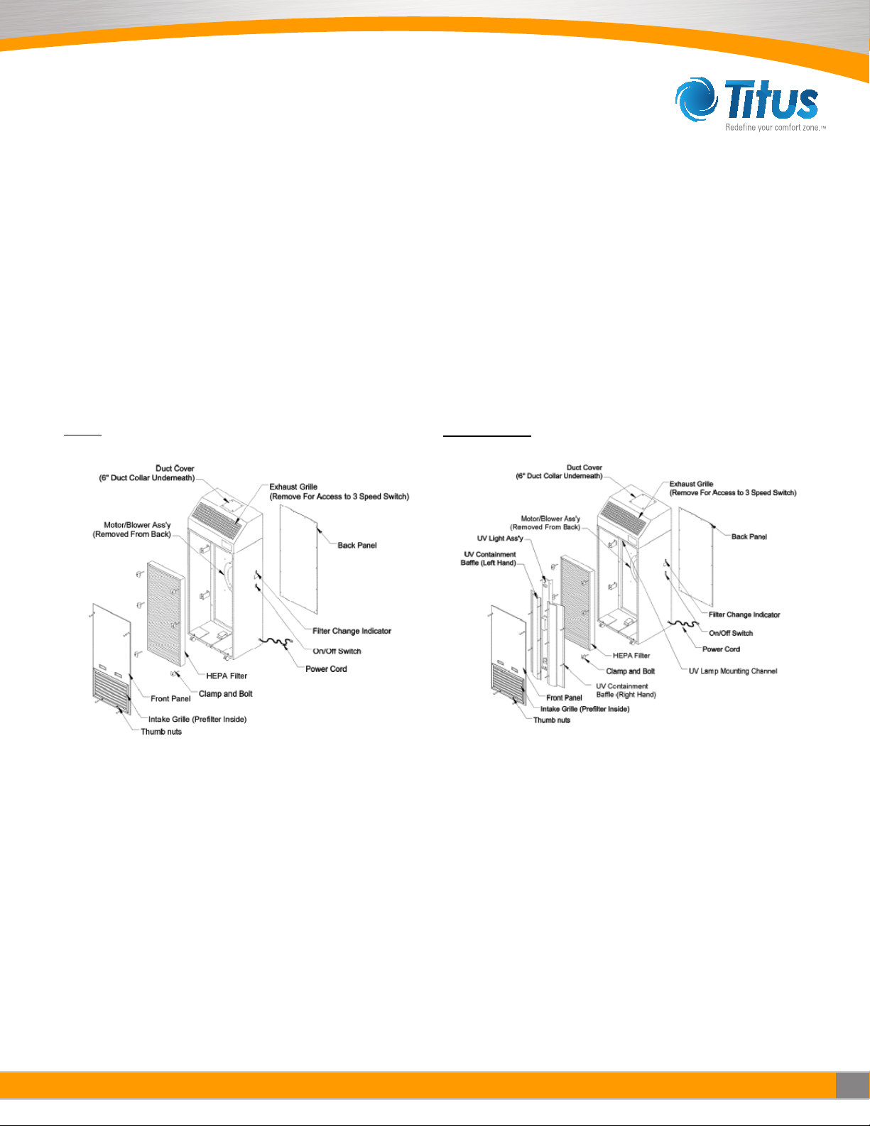
Parts Identification
THRC THRC with UV
*Note High Flow Unit shown *Note High Flow Unit shown

8
IOM - THRC Redefine your comfort zone. ™ | www.titus-hvac.com
IOM
THRC HF & LF
Cleaning the Unit
1. Periodic Cleaning of the unit may be done with a mild disinfecting soap and water solution. A 1% or 1/100 dilution of bleach
is an optional disinfectant3.
2. Exterior cabinet cleaning must be performed with the unit running. Wipe the exterior of the unit with a damp sponge or
cloth, paying particular attention to the prefilter intake grille.
3 Rutala WA, APlC guideline for selection and use of disinfectants, Am J lnfect Control 1996 Aug ; 24(4): 313-42.
Prelter Replacement
1. The pre-filter should be replaced every 60 to 90 days. Regularly replacing the pre-filter will maximize the life of the HEPA
filter. The THRC comes standard with an anti-microbial pleated pre-filter.
2. Clean the unit as described in the previous section.
THE FOLLOWING STEPS MUST BE PERFORMED WITH THE UNIT (FAN) RUNNING:
3. Spray a mist of phenolic disinfectant such as “Amply “ or “Lysol” into the air intake grille.
4. Remove the four (4) screws from the face of the intake grille and pull the grille out.
5. lnsert gloved hand into a red plastic, medical waste disposal bag. Grasp the top portion of the prelter with bagged hand
and gently pull outward. The airow of the unit will oer a resistance to pulling the prelter out.
6. Turn the bag inside out over the prelter then seal the bag for containment.
7. lnstall a new prelter and secure the grille by following step these instructions in reverse order of removal.
CAUTION: APPROPRIATE DECONTAMINATION PROCEDURES (SEE PAGE 11) MUST BE FOLLOWED PRIOR
TO REMOVAL OF THE ACCESS PANELS TO REPLACE THE HEPA FILTER OR OTHER PARTS. CONTACT YOUR
SAFETYOFFICE TO ASSURE IT CONFORMS TO YOUR FACILITY’S PROTOCOL.
Removal of Front and Rear Panels
1. Remove the front access panel by taking o the screw covers and removing the four (4) screws. The front panel may now
be lifted o.
2. Remove the 18 screws securing the rear access panel. The rear panel may now be lifted o.
Primary Filter Replacement
The CDC recommends that in any application, HEPA lters should be maintained meticulously and should be carefully installed
by adequately trained personnel wearing an appropriate respirator. A regular maintenance program should include procedures
for installation, removal and disposal of lter elements and a program to monitor the HEPA lter for possible leakage and for
lter loading.
The expected HEPA lter life should range from eighteen (18) months to two (2) years depending on the environment and
prelter maintenance schedule.The lter indicator light will give a warning of lter loading by ickering on high speed. When
the light stays on at high speed, the prelter should rst be changed. If the light stays on after prelter replacement, the HEPA
lter is recommended to be changed.
1. Remove the front access panel by following the instructions under removal of front and rear panels.
2. For THRC UV units, follow the steps in the below section to remove the UV Light Assembly.
3. Remove the six (6) bolts and clamps holding the HEPA filter in place.
4. In many cases, filters must be decontaminated before removal. See decontamination process for more information. Tilt
the top of the filter outward and slip a plastic biohazard bag over the top of the filter, and then wrap the bag over the bottom
of the filter.
5. Seal the bag for containment. Note: It may be necessary to use two (2) biohazard bags to fully contain the filter.
6. Remove the new HEPA filter from its container and install it in the reverse order of removal. Care must be taken when
handling the filter. Do not bump or squeeze the filter as this may damage the filter and render it non-effective.
Removal of the UV Light Assembly for the THRC UV
WARNING - Skin or eye damage may result from directly viewing the light produced by the lamp in this apparatus.
Always disconnect power before replacing the UV lamp or servicing. Replace lamp with lamp TUV 15W SLV,
manufactured by Philips for THRC Low Flow Replace lamp with TUV 30W SLV, manufactured by Phillips for THRC
High Flow.

9
IOM - THRC
Redefine your comfort zone. ™ | www.titus-hvac.com
1. Remove the front access panel by following the instructions under removal of front and rear panels. Set the front access
panel to the side.
2. Disconnect the three-pin connector located near the UV lamp ballast and remove the wires from the wire routing clamp.
3. Remove the five (5) screws on the left hand UV containment baffle, and then lift the baffle out of the unit and set it to the
side. Repeat this for the right hand UV containment baffle. (Note: This is for THRC High Flow model only)
4. Remove the two (2) screws that fasten it with the top of the UV lamp assembly.
5. Remove the remaining two (2) screws that fasten the mounting bracket to the cabinet and set the mounting bracket to
the side.
6. Remove the two (2) screws fastening the UV lamp assembly to the bottom of the cabinet.
7. Carefully remove the UV lamp assembly taking care not to touch the glass tube.
The expected life of the UV light tube is 9,000 hours. To remove the UV light follow the below instructions.
1. Rotate the light tube 90 degrees in either direction to enable removal (you should feel tension on the tube release). To
remove the light tube, carefully pull away from the UV lamp assembly, towards the HEPA lter. Dispose of the light tube
(or recycle) following local guidelines.
2. Use Clean latex gloves to ensure that the new light tube remains clean. Clean the new light tube using a cloth dampened
with a 10% alcohol (or ammonia) and water solution. To replace, reverse the order of removal.
Power Cord
1. With the back panel removed, unplug the white connector on the power cord.
2. Remove nut on ground wire.
3. Remove strain relief on the side of the unit.
4. Remove the old cord and replace with the new one by following the steps above in reverse order.
On/O Switch
1. With the back panel removed, unplug the white connector on the switch and squeeze the snap-in legs to remove switch
from side of the unit.
2. Install new switch by snapping it into the cutout and then connecting it to the white connector.
Speed Control Switch
1. Remove the exhaust grille by pushing down and lifting out.
2. Remove J-box screws.
3. Remove knob.
4. Remove switch screws.
5. Unplug connecting wires and replace with the new switch by following the steps above in reverse order.
Capacitor
1. With the back panel removed, remove one screw from capacitor strap. Note: Make sure to provide ample time for
capacitor to discharge.
2. Slide capacitor out.
3. Remove the rubber boot and disconnect wires.
4. Replace with the new capacitor by following the steps above in reverse order.
Filter Change Indicator Light
1. With the back panel removed, unplug the two (2) wires and push out the lter indicator light from the inside of the unit.
2. Replace the lter indicator light by following the step above in reverse order.
Motor Assembly Removal
1. The motor can only be removed from the front side of the unit. First ensure that the front panel, UV light assembly (for
UV units), and lter are removed. Refer to the removal of front and rear panels, primary lter replacment, and removal of
the UV light assembly sections.
2. Remove the screw fastening the green motor ground wire to the motor panel.
3. Remove the screw fastening the black wire clamp to the motor panel.
4. Most of the motor wires feed into a quick-connect socket. Disconnect this socket from its mating half.
5. Remove the six (6) screws fastening the motor ring to the panel and remove the motor assembly from the unit.
CAUTION:WHENREINSTALLINGTHEMOTORENSURETHATITDOESNOTTOUCHORPUNCTURETHEHEPAFILTER.

10
IOM - THRC Redefine your comfort zone. ™ | www.titus-hvac.com
IOM
THRC HF & LF
Relocating a Contaminated Unit
NOTE: USE PROPER PROTOCOL, GOWNING, AND PROTECTIVE MEASURES.
1. lf an existing unit is to be placed into storage for an extended period of time, remove and replace the prelter.
2. Turn the unit o and disconnect from power source.
3. Clean the exterior surfaces of the unit.
4. Unlock caster wheel locks and move unit to its new location.
Unit Decontamination
NOTE: USE PROPER PROTOCOL, GOWNING, AND PROTECTIVE MEASURES DURING UNIT DECONTAMINATION.
Should decontamination of the unit be required, it is recommend to follow basic guidelines and a modied prodedure based on
Decontamination of Large Spaces located in Biosafety in Microbiological and Biomedical Laboratories, 5th Ed. from the CDC.
Conrm with appropriate Biosafety and lndustrial Safety Professionals that the procedures meet your facility’s guidelines.
Decontamination should be performed by specialists with proper training and protective equipment.
The primary methods of space decontamination are:
• Paraformaldehyde Decontamination
• Hydrogen Peroxide Vapor
• Chlorine Dioxide Gas
After decontamination process has been completed, remove the HEPA lter. The lter can now be disposed of as general
waste.
Phenolic Decontamination
ln facilities where the above decontamination procedures are prohibited or not feasible, the unit can be disinfected by the
following procedure.
1. Remove the prelter.
2. After the intake grille and prelter are removed, turn the unit on, and with the unit running, spray a mist of phenolic
disinfectant such as Amphyl or Lysol into the air intake opening. Approximately two (2) to ve (5) ounces is adequate.
3. Remove the HEPA lter. Since the lter has not been decontaminated by the methods above, the lter should be disposed
of properly.
■Troubleshooting
Before attempting to service and repair the unit, use proper protocol and follow appropriate decontamination procedures
described in the following sections:
• Cleaning the Unit
•Prelter Replacement
• Relocating a Contaminated Unit
• Unit Decontamination
Inoperative Air Flow
1. Conrm that the power cord is plugged into the building receptacle and power is present.
2. Conrm that the unit power switch is turned “ON”.
3. Conrm the speed control is not in a position that is preventing airow. Recommended to change the position for
conrmation.
4. Check switch and internal wiring per Wiring Diagram (Section 6). Replace or repair faulty component(s).
5. Check the motor and replace if necessary.
6. Check the motor capacitor and replace if necessary. Recommended to change motor capacitor with motor replacement.
11
IOM - THRC
Redefine your comfort zone. ™ | www.titus-hvac.com
Low Air Flow
1. Check prelter for obstruction and remove obstruction as necessary.
2. Replace dirty prelter media.
3. Switch the speed control to the next higher airow setting.
4. Check power supply for proper voltage, amperage and distribution frequency.
5. Check for down-stream obstructions or erratic isolation room ventilation balance.
6. Replace HEPA lter if the air velocity remains low after checking all other causes of low air ow.
High Air Flow
1. Adjust the speed control down to the next lowest setting.
2. Verify all lters are properly in place.
Excessive Contamination
1. Replace HEPA lter.
2. Verify the HEPA lter is installed properly.
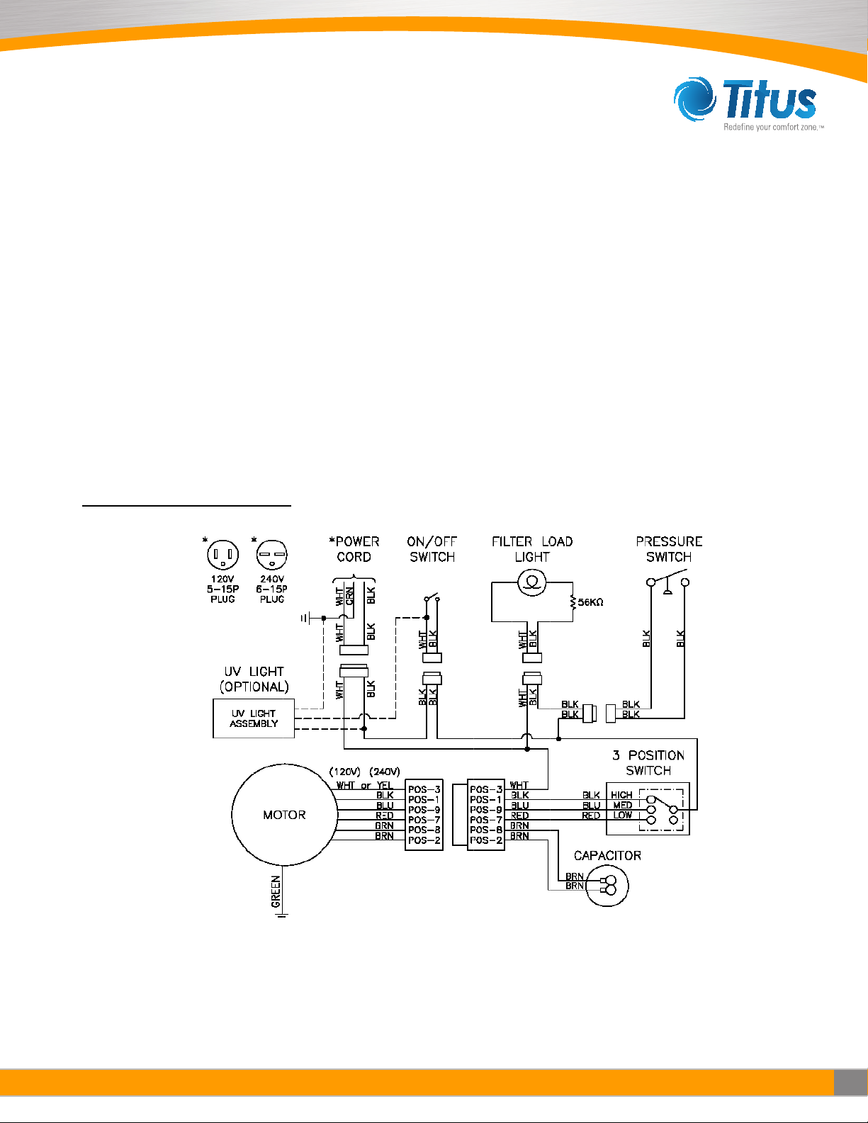
■Wiring Diagrams
THRC High Flow Wiring Diagram
12
IOM - THRC Redefine your comfort zone. ™ | www.titus-hvac.com
IOM
THRC HF & LF
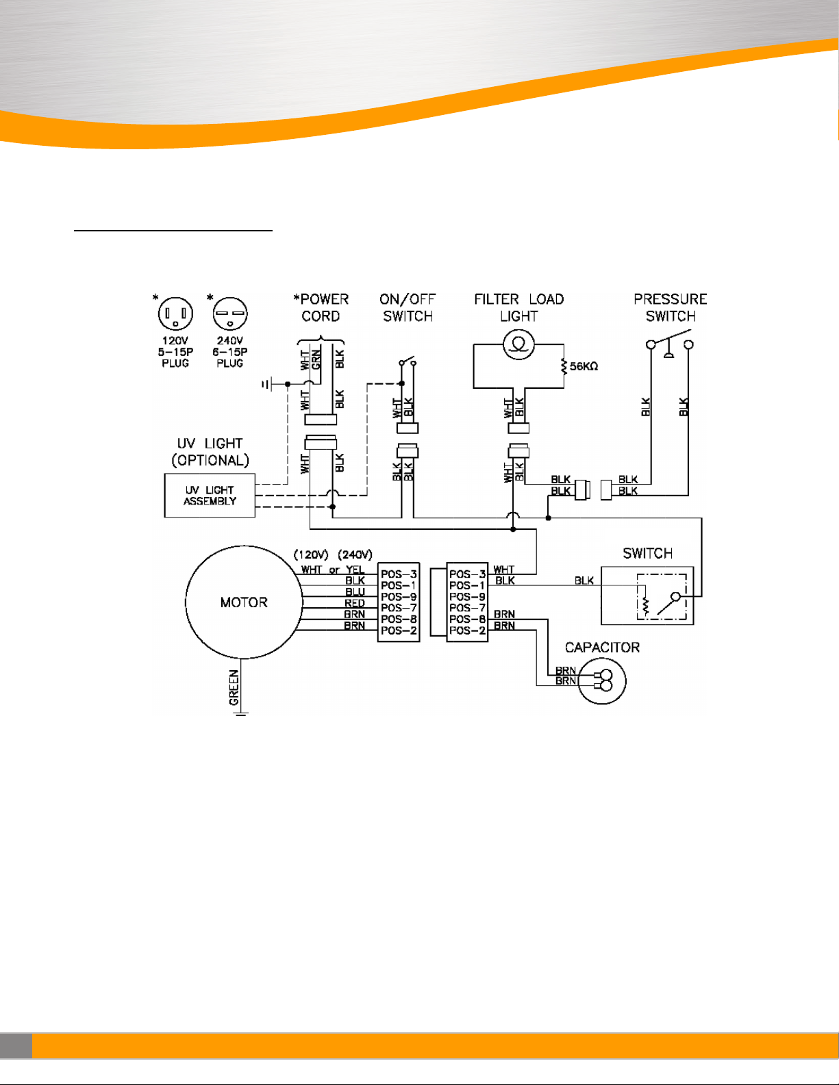
■Wiring Diagrams Cont.
THRC Low Flow Wiring Diagram

13
IOM - THRC
Redefine your comfort zone. ™ | www.titus-hvac.com
■Specifications
THRC High Flow
•Dimensions: 62.25 H x 23.66 W x 15.75 D (in.), 1581 H x 601 W x 400 D (mm)
•Weight: 250 lbs. (113 kg) ship weight
•Power Requirements: 6.9 A at 120V, 60 Hz, Single Phase, 3.5 A at 220V, 60 Hz, Single Phase
•Airow: 560 CFM (951 m3/hr) on Low ±10%, 690 CFM (1172 m3/hr) on Medium ±10%, 800 CFM (1359 m3/hr) on High ±10%
•HEPA Filter Media: 99.99% at 0.3 micron minimum eciency
•Prelter: MERV8 multi-pleat anti-microbial pleated prelter with frame
•Motor: 1/3 HP (0.25 kW), direct drive, three-speed, continuous duty
•Exhaust Port: 6-lnch (152.4mm) Duct Collar
THRC High Flow UV
•Dimensions: 62.25 H x 23.66 W x 19.75 D (in), 1581 H x 601 W x 502 D (mm)
•Weight: 285 lbs.(129 kg) ship weight
•Power Requirements: 8.0 A at 120V, 60 Hz, Single Phase, 4.0 A at 220V, 60 Hz, Single Phase
•Airow: 560 CFM (951 m3/hr) on Low ±10%, 690 CFM (1172 m3/hr) on Medium ±10%, 800 CFM (1359 m3/hr) on High ±10%
•HEPA Filter Media: 99.99% at 0.3 micron minimum eciency
•Prelter: MERV8 multi-pleat anti-microbial pleated prelter with frame
•Motor: 1/3 HP (0.25 kW), direct drive, three-speed, continuous duty
•Exhaust Port: 6-inch (152.4mm) Duct Collar
THRC Low Flow
•Dimensions: 38.25 H x 23.66 W x 15.75 D (in.), 972 H x 601 W x 400 D (mm)
•Weight: 153 lbs. (70 kg) ship weight
•Power Requirements: 2.8 A at 120V, 60 Hz, Single Phase, 1.5 A at 220V, 60 Hz, Single Phase
•Airow: 70 CFM (118 m3/hr) at minimum ±10% and 370 CFM (628 m3/hr) on High ±10%
•HEPA Filter Media: 99.99% at 0.3 micron minimum eciency
•Prelter: MERV8 multi-pleat anti-microbial pleated prelter with frame
•Motor: 1/4 HP (0.19 kW), direct drive, three-speed, continuous duty
•Exhaust Port: 6-lnch (152.4mm) Duct Collar
THRC Low Flow UV
•Dimensions: 38.25 H x 23.66 W x 19.75 D (in), 972 H x 601 W x 502 D (mm)
•Weight: 173 lbs.(79 kg) ship weight
•Power Requirements: 2.9 A at 120V, 60 Hz, Single Phase, 1.6 A at 220V, 60 Hz, Single Phase
•Airow: 70 CFM (118 m3/hr) at minimum ±10% and 370 CFM (628 m3/hr) on High ±10%
•HEPA Filter Media: 99.99% at 0.3 micron minimum eciency
•Prelter: MERV8 multi-pleat anti-microbial pleated prelter with frame
•Motor: 1/4 HP (0.19 kW), direct drive, three-speed, continuous duty
•Exhaust Port: 6-inch (152.4mm) Duct Collar

14
IOM - THRC Redefine your comfort zone. ™ | www.titus-hvac.com
IOM
THRC HF & LF
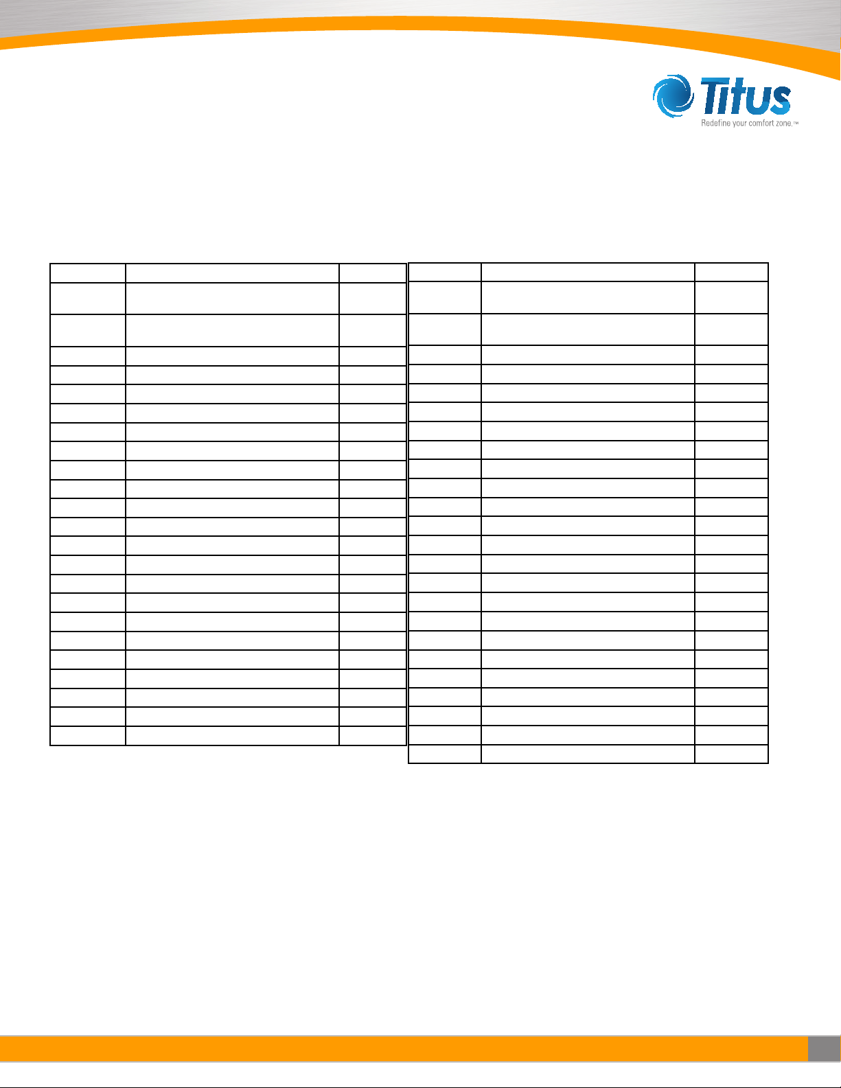
■Replacement Parts
THRC High Flow
Part No. Description Quantity
S62954-
WIRED Motor, 1/3 HP, 3-Speed, 115V 1
S63093-
WIRED Motor, 1/3 HP, 3-Speed, 220V 1
S24000 Motor/Blower Assembly, 120V 1
S24000-002 Motor/Blower Assembly, 220V 1
63252 Air Inlet Ring 1
63270 Blower Wheel 1
63775 3-Speed Switch 1
63779-002 Switch Knob 1
23888 Power Cord - 120V 1
23888-002 Power Cord - 220V 1
140204-002 Motor Capacitor 15 mfd, 120V 1
60078 Motor Capacitor 5 mfd, 220V 1
63027 Air Pressure Switch 1
61400 Filter Indicator Light 1
63352 Prelter 1
S69391-001 HEPA Filter 1
S69391-002 ULPA Filter 1
62973 Caster 2
62974 Caster with Brake 2
257738-001 6-inch Duct Collar 1
257633-001 Exhaust Cover Plate for THRC 1
11055 8-inch A/C Collar with Flange for 100% 1
267745-001 Intake Grille - Painted 1
37453 Exhaust Grille 1
THRC High Flow UV
Part No. Description Quantity
S62954-
WIRED Motor, 1/3 HP, 3-Speed, 115V 1
S63093-
WIRED Motor, 1/3 HP, 3-Speed, 220V 1
S24000 Motor/Blower Assembly, 120V 1
S24000-002 Motor/Blower Assembly, 220V 1
63252 Air Inlet Ring 1
63270 Blower Wheel 1
63775 3-Speed Switch 1
63779-002 Switch Knob 1
23888 Power Cord - 120V 1
23888-002 Power Cord - 220V 1
140204-002 Motor Capacitor 15 mfd, 120V 1
60078 Motor Capacitor 5 mfd, 220V 1
63027 Air Pressure Switch 1
61400 Filter Indicator Light 1
63352 Prelter 1
S69391-001 HEPA Filter 1
S69391-002 ULPA Filter 1
62973 Caster 2
62974 Caster with Brake 2
257738-001 6-inch Duct Collar 1
257633-001 Exhaust Cover Plate for THRC 1
11055 8-inch A/C Collar with Flange for 100% 1
267745-001 Intake Grille - Painted 1
37453 Exhaust Grille 1
24392-001 UV Bae Assembly 1
60265 Replacement UV Germicidal Lamp 1
15
IOM - THRC
Redefine your comfort zone. ™ | www.titus-hvac.com
■Replacement Parts (continued)
THRC Low Flow UV
Part No. Description Quantity
S267793-
001 Motor, 1/4 HP, 3-Speed, 115V 1
S267793-
002 Motor, 1/4 HP, 3-Speed, 220V 1
S24332-015 Motor/Blower Assembly, 120V 1
S24332-016 Motor/Blower Assembly, 220V 1
63252 Air Inlet Ring 1
63270 Blower Wheel 1
271806-001 Speed Control, 120V 1
271806-002 Speed Control, 220V 1
23888 Power Cord - 120V 1
23888-002 Power Cord - 220V 1
61485 Motor Capacitor 10 mfd, 370VAC 1
63027 Air Pressure Switch 1
61400 Filter Indicator Light 1
63352 Prelter 1
S69391-005 HEPA Filter 1
S69391-006 ULPA Filter 1
62973 Caster 2
62974 Caster with Brake 2
257738-001 6-inch Duct Collar 1
257633-001 Exhaust Cover Plate for THRC 1
11055 8-inch A/C Collar with Flange for 100% 1
267745-001 Intake Grille - Painted 1
37453 Exhaust Grille 1
60265-002 Replacement UV Germicidal Lamp 1

16
IOM - THRC Redefine your comfort zone. ™ | www.titus-hvac.com
IOM
THRC HF & LF
■Airflow Measurement & Testing

605 Shiloh Rd
Plano TX 75074
ofc: 972.212.4800
fax: 972.212.4884
Redefine your comfort zone. ™ | www.titus-hvac.com
This manual suits for next models
3
Table of contents
Popular Air Cleaner manuals by other brands


Sharp
Sharp FP-F30U Operation manual

Carrier
Carrier INFINITY 1625 Installation and operating instructions

Airthereal
Airthereal Glory Days AGH550 user manual

UltraViolet Devices
UltraViolet Devices High Output UV Device V-Flex Installation & owners guide

3M
3M Filtrete FAP-C01BA-G1 Series manual

Mini Gadgets
Mini Gadgets BBSAirFreshener user manual