TJERNLUND XCHANGER X2R User manual

INSTALLATION INSTRUCTIONS
MODEL X2R
OWNER'S INSTRUCTIONS, DO NOT DESTROY
Copyright © 2014, Tjernlund Products, Inc. All rights reserved. P/N 8504202
THIS DEVICE MUST BE INSTALLED BY A
QUALIFIED PERSON.
READ INSTRUCTIONS CAREFULLY PRIOR TO
INSTALLATION AND OPERATION OF THE XCHANGER.
REV. A 07/14
TJERNLUND PRODUCTS, INC.
1601 Ninth Street • White Bear Lake, MN 55110-6794
PHONE (800) 255-4208 • (651) 426-2993 • FAX (651) 426-9547
Visit our web site • www.tjernlund.com

1
TABLE OF CONTENTS
Descriptions and Specifications.......................................................................................................................................1
Installation Restrictions....................................................................................................................................................1
Cautions .......................................................................................................................................................................1-2
Recommended Methods and Patterns of Operation....................................................................................................2-3
Recommended Installation and Termination Locations................................................................................................3-4
XCHANGERTM Installation..............................................................................................................................................4-6
Maintenance ....................................................................................................................................................................6
How to Obtain Service & Warranty ..............................................................................................................................6-7
Replacement Parts & Accessories ..................................................................................................................................7
XCHANGERTM is a trademark of Tjernlund Products, Inc.
Tjernlund Products welcomes your comments and questions. Call us at (651) 426-2993, (800) 255-4208, Fax (651) 426-9547, email us
at [email protected] or write to: Customer Service, Tjernlund Products, Inc., 1601 Ninth Street, White Bear Lake, MN 55110-6794.
DESCRIPTION
The XCHANGERTM model X2R is a dual fan mechanical ventilator capable of exhausting inside air, providing fresh outside air or provid-
ing a balanced air exchange. The fans can be independently switched on or off or be easily reversed to provide fresh outside air or
exhaust inside air. The XCHANGERTM can be operated by a standard plug-in timer or Tjernlund’s optional DH2P dehumidistat control
which operates the fan(s) based on the relative humidity sensed inside the home. The DH2P control includes an “On” setting that will
operate the fan(s) continuously or it can be turned “Off” so the fan(s) do not operate during undesirable seasons.Tjernlund’s optional
SCP speed control kit is also available to vary speed of fans if desired. See accessories on page 7.
X2R SPECIFICATIONS
GENERAL INFORMATION
Each XCHANGERTM is electrically factory line tested before shipment. After opening carton, Inspect thoroughly for hidden damage.
INSTALLATION RESTRICTIONS
WARNING: Improper installation, adjustment, alterations, service or maintenance can cause injury or property damage. Refer to
this manual. For assistance or additional information consult a qualified installer, service agency or the equipment supplier.
WARNING: Sufficient air is needed for proper combustion and exhausting of gases through the flue (chimney) of fuel burning equip-
ment to prevent backdrafting. Follow the heating equipment manufacturer’s guideline and safety standards such as those
published by the National Fire Protection Association (NFPA), and the American Society for Heating, Refrigeration and
Air Conditioning Engineers (ASHRAE), and the local code authorities.
WARNING: Do not exhaust air from mechanical room unless makeup air is also supplied or equipment in mechanical room is sealed
combustion. Carbon monoxide poisoning may result. Use the DT2-6 6” duct take-off kit so exhaust can be removed from
outside the mechanical room if necessary.
Observe proper location of hood as described on page 3. The XCHANGERTM must only be installed with the hood on an exterior wall.
Do not discharge intake air onto water pipes or other equipment which may be affected by temperature extremes.
CAUTIONS
WARNING: Failure to install, maintain and/or operate the XCHANGERTM in accordance with manufacturer’s instructions may result in
conditions that can produce bodily injury and property damage.
MODEL X2R XCHANGER
Rough-in Wall Opening Dimensions:
13 1/4” x 6 1/2” Oval opening - utilize included template
8061034
FLEXIBLE TUBING
NOMINAL 6" DIAMETER
BY INSTALLER
1 FAN 2 FANS
Voltage 120 120
Watts 20 40
Amps 0.3 0.6
CFM 90 180

2
Disconnect power supply to fans and/or accessory controls when reversing fan direction or servicing the XCHANGERTM. Failure to do
so may result in personal injury and/or equipment damage.
Make certain the power source is adequate for the XCHANGERTM requirements. Do not add the XCHANGERTM to a circuit where the
total electrical load is unknown.
TJERNLUND OPTIONAL DH2P DEHUMIDISTAT CONTROL MODULE OPERATION
The DH2P control module includes an adjustable dehumidistat control which activates the fan(s) if the relative
humidity rises above the selected set-point. It is generally recommended to maintain a Relative Humidity (RH)
below 60% to inhibit mold growth. The dehumidistat can be turned fully clockwise to the ‘on’ position for con-
stant fan(s) operation or it can be turned fully counter-clockwise to ‘off’ during seasons or times when it is not
desired for the XCHANGERTM fan(s) to run. Each fan can be independently turned on/off by its fan switch on control
module.
STANDARD PLUG-IN TIMER OPERATION
A standard adjustable timer can also be utilized for timed operation of the XCHANGERTM fan(s). Plug timer into standard outlet and
plug XCHANGERTM fans into wall timer.
TJERNLUND OPTIONAL SCP SPEED CONTROL OPERATION
Tjernlund’s optional SCP speed control can be used to vary the speed of the XCHANGERTM fans. Plug SCP speed control into stan-
dard outlet and plug XCHANGERTM fans into SCP speed control.
RECOMMENDED PATTERNS OF OPERATION
If using the optional DH2P dehumidistat control, the X2R fans can be cycled automatically based on the relative humidity level of the
house or it can be operated based on recommendations below. It is generally recommended to maintain a Relative Humidity (RH)
below 60% to inhibit mold growth.
A standard plug-in wall timer can be programmed based on the lifestyle or needs of the occupants. For example, a family with smok-
ers may want to cycle the XCHANGERTM more frequently than a family of non-smokers.
Another timed method may be to cycle the XCHANGERTM during peak usage of exhaust fans, such as bathroom, kitchen, laundry or
utility. Outdoor air should be brought in at these peak times to help balance out pressure inside the house.
The XCHANGERTM can be cycled on and off at regular intervals to periodically provide fresh air to the home, exhaust stale air or have
one fan bring air in and the other fan exhaust air for a balanced air exchange. It can also be ran like an economizer to bring outside
air in during evening time when it is cooler outside.
HYPOTHETICAL XCHANGER OPERATION BASED ON LIFESTYLE
The example below shows a possible way in which cycling times of the XCHANGERTM may be determined based on household
occupant lifestyles.
6:00 A.M. to 9:00 A.M. = Outside fresh air should be brought into the house to compensate for morning routines. Bathing, cooking,
laundry and other activities such as smoking necessitate that outside fresh air to be brought in. Depressurization of the house at these
times is common with many exhaust fans running at one time.
9:00 A.M. to 4:00 P.M. = House is normally vacant with occupants at work or school. Cycle XCHANGERTM on and off for 15 minute
intervals per hour to assure fresh air is supplied to the house.
4:00 P.M. to 8:00 P.M. = Outside fresh air should be brought into the house to compensate for evening routines. Bathing, cooking,
laundry and other activities such as smoking necessitate that outside fresh air to be brought in. Depressurization of the house at these
times is common with many exhaust fans running at one time.
8:00 P.M. to 6:00 A.M. = All members of the household are usually present. Outside fresh air is needed to dilute occupant generated
carbon dioxide during sleeping. Cycle XCHANGERTM on and off for 15 minute intervals, with occasional 30 minute intervals to assure
fresh air is supplied to house.

XCHANGER OPERATION BASED ON AIR CHANGES PER HOUR
This method of operation can be used to supplement or provide for guaranteed air change rates. Table 1 shows the constant Cubic
Feet Per Minute (CFM) of air necessary to produce the desired Air Change Per Hour rate (ACH), assuming natural infiltration of out-
side air at a rate of .10 ACH. Square footage is determined by calculating the finished living space of the house. Garages and crawl
space should not be included. The constant CFM figures shown assume that the living space has standard 8 foot ceilings.
1. Determine square footage of house living space on left hand column.
2. Pick desired air change rate from top row.
3. Locate intersection of these points to determine constant CFM that should be obtained to meet desired ACH.
The XCHANGERTM will provide 180 CFM with both fans and 90 CFM with one fan operating. Where the CFM delivery of the XCHANG-
ERTM exceeds that listed in Table 1, a standard plug-in timer can be set so the XCHANGERTM is cycled to obtain the
desired ACH or Tjernlund’s optional SCP speed control may be used.
EXAMPLE
3000 square feet of living space
.2 ACH desired ventilation rate equals 40 CFM
XCHANGERTM capacity of 90 CFM (with one fan running)
In this example the plug-in timer may be set so that the XCHANGERTM operates for one half hour straight each hour or two fifteen
minute periods each hour.
RECOMMENDED INSTALLATION LOCATION
The XCHANGERTM may be mounted anywhere in the house. Mount in a location where it is accessible for reversing fans seasonally or
for maintenance.
WARNING: Do not exhaust air from mechanical room unless makeup air is also supplied or equipment in mechanical room is sealed
combustion. Carbon monoxide poisoning may result. Use the optional DT2-6 6” duct take-off kit so exhaust can be
removed from outside the mechanical room if necessary.
It is required that the XCHANGERTM be installed in a location where it will not be directed at the occupants. Do not discharge intake air
onto water pipes or other equipment which may be affected by temperature extremes.
Do not terminate adjacent to thermostat. Outside temperatures can disrupt normal thermostat operation.
Do not terminate within three feet from a barometric draft control or intake grille of a heating appliance.
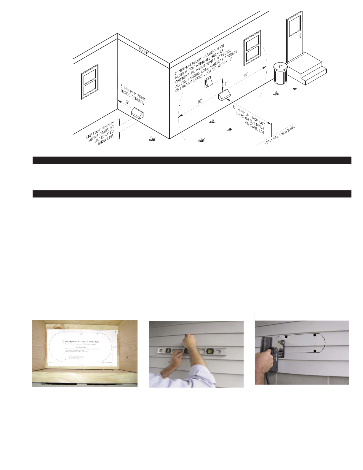
XCHANGER HOOD TERMINATION CLEARANCES
Install XCHANGERTM in accordance with BOCA national Mechanical Codes M-306.1 and M-306.1.1 as follows, (See Diagram A).
M-306.1 LOCATION: Outside air exhaust and intake openings shall be located a minimum of 10 feet (3048mm) from lot lines or build-
ings on the same lot. When openings front on a street or public way, the distance shall be measured to the centerline of the street or
public way.
M-306.1.1 INTAKE OPENINGS: Outside air intake openings shall be located a minimum of 10 feet (3048mm) from any hazard or
noxious contaminant such as vents, chimneys, plumbing vents, streets, alleys, parking lots and loading docks. When a source conta-
minant is located within 10 feet (3048mm) of an intake opening, such opening shall be located a minimum of 2 feet (610mm) below
the contaminant source.
IN ADDITION TO THESE CODES THE MANUFACTURER RECOMMENDS THAT:
• The XCHANGERTM hood should be a minimum of 1 foot above grade or anticipated snow line.
• The XCHANGERTM hood should be a minimum of 3 feet from an inside corner of the building.
3
TABLE 1
4
INSTALLATION (TOOLS REQUIRED)
• Reciprocating saw • 5/16” nut runner or socket • Siding tools (dependent on exterior finish)
• Drill and 1/2” bit • Phillips screwdriver • Level
INSTALLATION
NOTE: Before cutting opening through wall, confirm XCHANGERTM hood termination clearances are met as noted on bottom of page 3.
1. A) Center X2R mounting template and tape to the rim joist between the floor joists/trusses XCHANGERTM will be mounted through,
(See Diagram B).
B) If XCHANGERTM is not installed between floor joists or trusses, attach the template to the wall it will be exiting, ensuring
XCHANGERTM will be level.
2. CAUTION: When cutting or drilling into wall, do not damage electrical wiring and other hidden utilities. Using a 1/2” bit, drill pilot
holes noted on the template from inside through rim joist, wall board, siding, etc., keeping drill bit perpendicular to the wall. 1/2” bit
must be long enough to penetrate through exterior.
3. Use a level to mark (4) holes drilled in step 2 and connect the holes on building exterior, (See Diagram C). Use provided X2R
oval template to align pilot holes and trace the remaining outline for opening. Use a saw to remove material between marks, (See
Diagram D).
DIAGRAM B DIAGRAM C DIAGRAM D
CENTER AND LEVEL TEMPLATE BETWEEN JOISTS /
TRUSSES OR PLACE ON WALL X2R XCHANGER
WILL EXIT.
DRILL (4) 1/2” CORNER HOLES THROUGH WALL
FROM INTERIOR AND CONNECT HOLES ON
EXTERIOR WITH A LEVEL. ALIGN TEMPLATE
WITH HOLES AND TRACE REMAINING LINES.
CUT OVAL TEMPLATE OPENING ALONG
MARKED LINES.
DIAGRAM A
Table of contents
Other TJERNLUND Ventilation Hood manuals


Popular Ventilation Hood manuals by other brands

Gorenje
Gorenje S3 IHGC963S4X manual

KOBE
KOBE ISX2136SQB-1 Installation instructions and operation manual

U.S. Products
U.S. Products ADVANTAGE-100H Information & operating instructions

Kuppersberg
Kuppersberg DUDL 4 LX Technical Passport

Framtid
Framtid HW280 manual

Thermador
Thermador HGEW 36 FS installation manual


