TKB Home TZ75 User manual

-1-
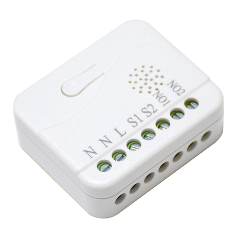
TZ75 Roller shutter controller
Note: This module must be“Included in the network”,and suitable for where it will be
permanently installed. The proper operation of this node in the mesh network is
dependent on it knowing it’s location with respect to other nodes. You can not "test
bench" configure this module, then install.
In the front casing, there is an on/off button with LED indicator which is used to
toggle switch on and off or carry out inclusion, exclusion, reset or association.
When first power is applied, its LED flashes on and off alternately and repeatedly
at 1-second intervals. It implies that it has not been assigned a node ID and can not
work with Z-Wave enabled devices.
The table below lists an operation summary of basic Z-Wave functions. Please
T M
refer to the instructions for your Z-Wave certificated primary co ntroll e r to
access the setup function, and to include/exclude/associate devices.
The in-wall Roller Shutter Controller is designed to switch rise/lower roller shutter
connected to its terminals using radio waves, controllers and a push button directly
connected to this Roller Controller.
TM
The in-wall Roller Shutter Controller is a transceiver which is a Z-Wave enabled
TM
device and is fully compatible with any Z-Wave enabled network. Slim design let
the Controller can easily hide itself into the wall box and that will be good for the
house decoration.
The new smart relay calibration technology can reduce the inrush current caused by
the load and let the module work perfectly with many kind of Roller Shutter. This
in-wall Roller Shutter Controller is able to detect position of the Shutter by using the
patterned power measuring method, so it can be remote controlled not only fully up
or down , but also can be adjusted to ex. 30% or 50%. And when manual controlled
by push button, the controller also can memorize the position and send the new shu
-tter position to its controller (ex. IP-Gateway).

-2-
To distinguish what mode the TZ75 is in, view from the LED for identification.
No matter up or down, close or open, Led will flash every two seconds while
Motor activate.
Under normal operation, when the TZ75 has not been allocated a node ID,
the LED flashes on and off alternately at 1-second intervals. By pressing S1
S2 or Include button, it will stop flashing temporarily. However, after discon
LED Indication
Group 1:lifeline
2. There are two groups for the switch
Each group can associate max five devices.
(Profile MSB=0x00,Profile LSB=0x01)
ID is excluded
-nect and reconnect the TZ75, the LED will flash on and off alternately at 1-
second intervals.
When overload state occurs, the TZ75 is disabled of which LED flashes on
and off alternately at 0.5 second intervals. Overload state can be cleared by
disconnect and reconnect the TZ75 to the main power .
Installation and operation
1. put the in wall TZ75 into a wall box and connect the AC power wire L, N to
TZ75 connector L, N.
2. Connect the wall switch to the TZ75 .
3.It is important to carry out a shutter calibration process before you control the
shutter to move. Press inclusion button over 3 seconds and release before the
6th second, the roller shutter controller will start the shutter calibration process.
The process is composed of three continue stages. The shutter move to the TOP
in first stage, and move to the BOTTOM in second stage, and move to the TOP
again in third stage. Then TZ75 will know the total range of UP and DOWN.
4.During the shutter calibration process, any emergencies happen you can press
and release the include button to stop the process.
5.If user found the direction is reverse, this may because the wrong connection
of NO1 and NO2 to the motor, please change NO1 and NO2 connection and exe-
cute calibration process again.
6.To manually switch up and down of the shutter, simply press S1 or S2 .
7.TZ75 built in meter function and can read the Watt , KWh, V(Voltage), I(Current) ,
PF(Power Factor) of the load by using Z-Wave command class.
8.TZ75 have overload protection function, and can help to prevent short circuit
caused by load.
Z-Wave Configuration
Watt Meter
Report period
KWH Meter
Report period
Threshold of Watt
for load caution
Threshold of KWH
for load caution
Configuration
Parameter Dedault
Unit
Value
Size
(Byte)
Function Description
1
2
2
2
2
2
3
4
0x01-
0x7FFF
0x01-
0x7FFF
10-1100
0-10000
5s 720
10min 6
1Watt 1100
Kwh 0
5*720s=3600s=1hour
6*1min=1hour
Watt Meter Report Period:
If the setting is configured for 1hour (set value =720), the TZ75 will report its
instant power consumption every 1 hour to the node of correspond Group. The
maximum interval to report its instant power consumption is 45 hours (5s*32767
/3600=45hr). Default value is 1 hour
KWH Meter Report Period:
If the setting is configured for 1hour (set value =6), the TZ75 will report its Accu-
mulated Power Consumption (KW/h) every 1 hour to the node of correspond
Group. The maximum interval to report its Accumulated Power Consumption
(KW/h) is 227.55 days (10min*32767/1440=227.55 days). Default value=1 hour
-3-

-4-
Threshold of Watt for Load Caution
This is a warning when the wattage of load over the preset threshold value,
If the setting value is 1100, when the load wattage over this value, TZ75 will
send Watt Meter Report command to the node of correspond Group. Default
value=1100W.
Threshold of KWh for Load Caution
This is a warning when the KWh of load over the preset threshold value, If
the setting value is 10000, when the Accumulated Power Consumption of
Relay1 or Relay2 over this value, TZ75 will send KWh Meter Report comma-
nd to the node of correspond Group, minimum value is 1KWh and default
value is 0kWh.It means no warning when the KWH of load over the preset
threshold value and not send KWH Meter Report.
Z-Wave Supported Command Class
COMMAND_CLASS_SWITCH_BINARY
COMMAND_CLASS_BASIC
COMMAND_CLASS_MANUFACTURER_SPECIFIC_V2
COMMAND_CLASS_VERSION
COMMAND_CLASS_ASSOCIATION
COMMAND_CLASS_METER_V3
COMMAND_CLASS_CONFIGURATION
COMMAND_CLASS_SWITCH_MULTILEVEL_V3
Troubleshooting
Sympton Cause of failure Recommendation
The TZ75 not working
and LED off
1. The TZ75 is not connect
to the Main power
2.The TZ75 break down
The shutter move direction is reverse
1. Check power connections
2. Don’t open up the TZ75
and send it for repair.
Wrong connection of NO1
and NO2 to the motor
Swap the NO1 No2
connection
Tz75 LED light work fine
But can not control
1. No association setting
2. Same frequency
interference
1. Carry out association
2. Wait for a while to re-try
Resistive Load 1100W/600W(EU/US) max
110~240VAC
Operating Voltage
Maximum Load
Range
Operating Temperature
Frequency Range
0℃~40℃
Specifications subject to change without notice due to continuing product.
868.4MHz(EU) 908.42MHz(US) 921.42MHz(AUS)
Minimum 40m in door 70m outdoor line of sight
Specification
TZ75-V1.0-2017.3.21
-5-
Warning:
1.Do not dispose of electrical appliances as unsorted municipal waste , use separate
collection facilities.
2.Contact your local government for information regarding the collection systems available.
3.If electrical appliances are disposed of in landfills or dumps, hazardous substances can leak
into the groundwater and get into the food chain, damaging your health and well-being.
4.When replacing old appliances with new one, the retailer is legally obligated to take back
your old appliance for disposal at least for free of charge.
Limited Warranty:
Product is warranted against defects in material and workmanship for one year. We will
replace it free of charge and does not issue any refunds. This warranty extends only
to wholesale customers who buy through our Corporation authorized distribution channels.
Our Corporation does not warrant this product to consumers.
This warranty does not apply to:
(a) damage to units caused by accident, dropping or abuse in handling, or any negligent use.
(b) units which have been subject to unauthorized repair, taken apart,or otherwise modified.
(c) units not used in accordance with instruction.
(d) damages exceeding the cost of the product.
(e) transit damage, initial installation costs, removal cost, or reinstallation cost.
Wiring diagram
Product size (mm)
L: Line voltage input
NO1,NO2: motor connector
N: Line neutral
S: Connect to wall switch input
Other TKB Home Controllers manuals
Popular Controllers manuals by other brands

Nidec
Nidec LEROY-SOMER R450 Installation and Maintenance
Danfoss
Danfoss VLTAutomationDrive FC 360 quick guide
Granville-Phillips
Granville-Phillips Series 330 instruction manual
APS
APS REG-6S-100 instruction manual
HikRobot
HikRobot VB2200 Series user manual
Siemens
Siemens SIPART DR19 Assembly and installation guide
