TKE TMM-1 User manual
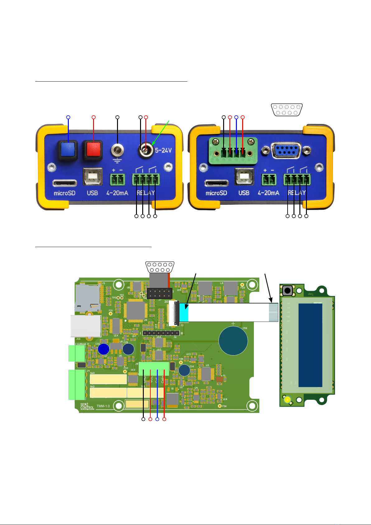
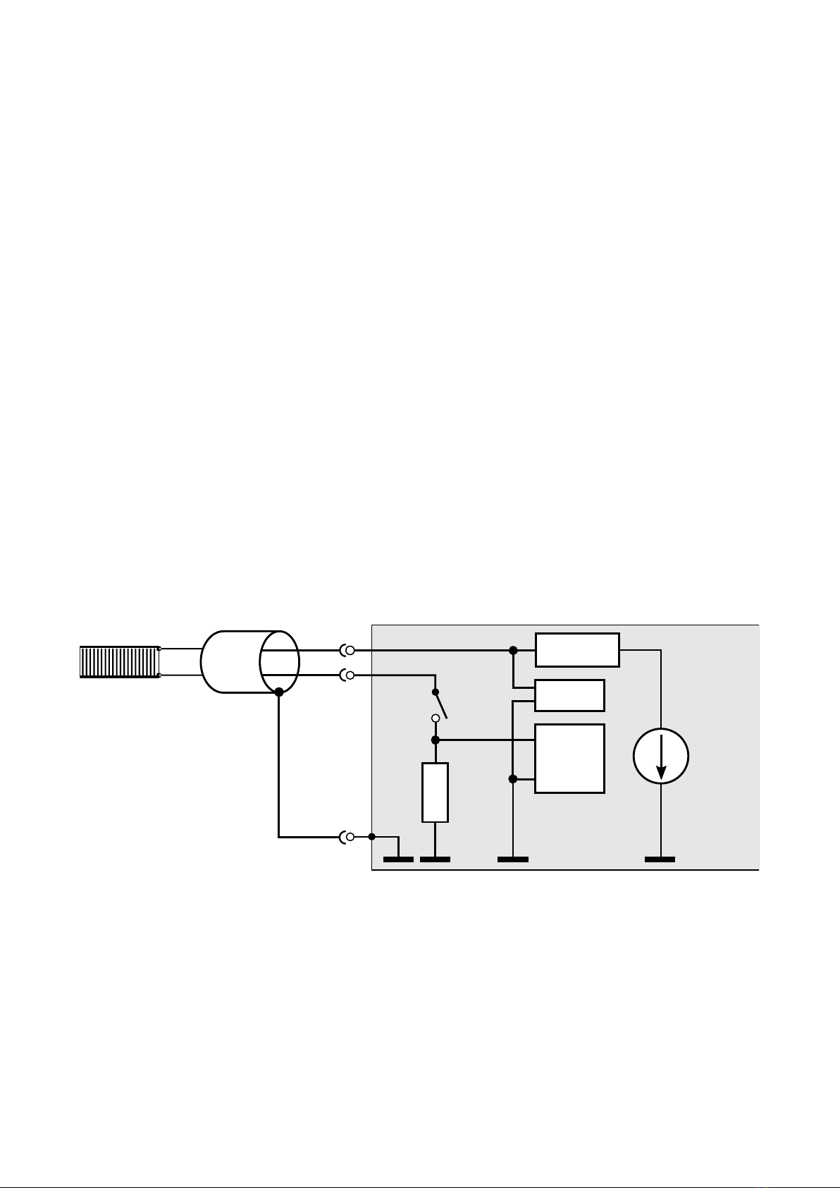
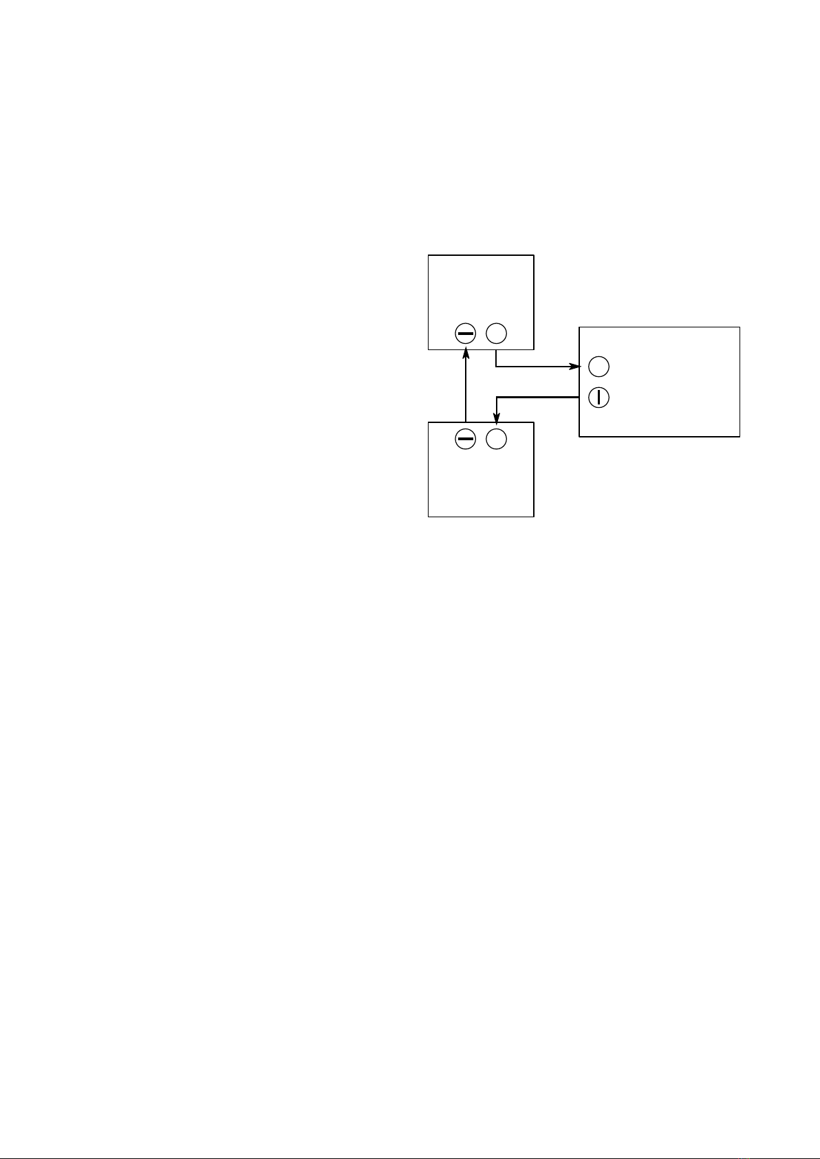
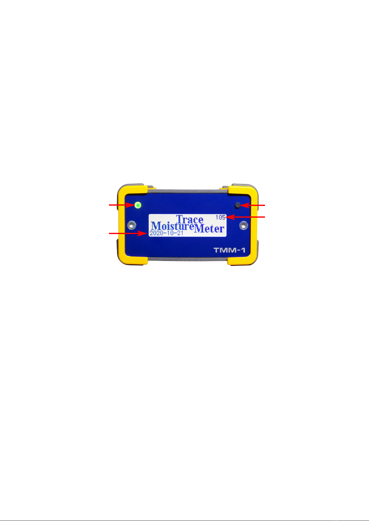
TKE
TE C H N I S C H E R K U N D E N D I E N S T & E N T W I C K L U N G
NO R B E R T G E R H A R D T
TMM-1 Trace Moisture Meter
Operator's Manual
0 Abstract
The most basic features of the TMM-1 can be used without computer: Measure the
humidity, determine amounts of water and capture measured data. The needed steps are
explained in this handbook.
All advanced capabilities and confi uration possibilities are unlocked with the Q-Moisture
software. Its usa e is described in the Q-Moisture handbook.
Pro rammers and system inte rators who wish to develop their own operatin software or
inte rate the device in their own software environment, will find the needed interface
descriptions in the documents TMM-1 Command Line Getting Started and Trace
Moisture Meter US API.
1
1 Connectors......................................................................................................2
1.1 Power Supply...........................................................................................3
1.2 Cell Terminals..........................................................................................3
1.3 USB Interface...........................................................................................3
1.4 Analo ue Output......................................................................................4
1.5 Relay Outputs..........................................................................................4
1.6 RS232 Interface.......................................................................................4
1.7 Display Connector....................................................................................5
1.8 microSD Card..........................................................................................5
2 Local Operation...............................................................................................6
2.1 Si nal LED...............................................................................................6
2.2 Pushbutton...............................................................................................7
2.2.1 Display Pa e 1: Current Gau e.......................................................7
2.2.2 Display Pa e 2: Inte ral Gau e.......................................................7
2.2.3 Display Pa e 3: Operational States.................................................8
2.2.4 Display Pa e 4: Data Lo er...........................................................8
3 Technical Specifications................................................................................10

1 Connectors
Laboratory Panel (LAB) / Industry Panel (IND)
Printed Circuit Boards without case
2
AB
1
2
3
45
678
9
GND
VCC
GND
Cell +
Cell -
VCC
GND
Cell +
Cell -
GND
RX
TX
CTS
RTS
RS232
A
B
Ø DC Jack:
5.5mm x 2.1mm
Relay B
Relay B
Relay A
Relay A
Contacts Down Contacts UpD-Sub 9 pin Female
12345
6789
RS232
4-20mA (+)
4-20mA (-)
GND
VCC
Cell (+)
Cell (-)
microSD
microSDHC
microSDXC
USB Type B

1.1 Power Supply
The device can be powered at the same time (redundant) from USB and the DC power
jack. It is protected a ainst false polarity and current limited to 750 mA.
•Volta e: 5 ... 24 V ±10%
•Power consumption: max. 3,3 W
•Power loss support time at 24V: 200 ms (worst case), 750 ms (dry cell, display illu-
mination and relays off)
•Recommended power supply: 24V, min. 6W, DC jack inner diameter 2.1 mm, outer
diameter 5.5 mm.
1.2 Cell Terminals
The electrolytic cell is connected here. The polarity is not of importance but the cell may
temporarily show an elevated or reduced sensitivity when the polarity is reversed durin
operation.
There is no limit in cable len th. However, couplin of noise should be avoided. If the cell
cable needs to be routed to ether with noisy lines, the use of a shielded cable is recom-
mended. Connect the shieldin to GND at the TMM-1 case and leave it open at the cell.
In any case, the minus terminal must never be connected to GND.
1.3 US Interface
The TMM-1 is equipped with a Full Speed USB interface (USB 2.0 at 12 Mbit/s) as its
central data I/O port. It appears at the PC as an FTDI serial interface device, the manual
installation of a driver is not needed. All reco nized TMM-1's will be listet in the Q-Mois-
ture software, then you can connect to one of them to remote control it.
3
10 Ω
Relay C
Cell -
ADC
24 Bit
+
-
Current limit
0.1-100 mA
Generator
0 - 25 V
Cell +
GND
ADC
10 Bit
-
+
optional
shieldin
TMM-1 Case
Cell

In case the TMM-1 is solely powered via USB, it is recommended to use a USB cable of
ood quality (thick) and not lon er than 3 meters to keep the volta e drop low. If the device
is operated behind a USB hub, it must provide its own power supply (powered hub).
It is also possible to operate the device from a USB char er or a USB power bank. These
sources must comply with the USB DCP standard (Dedicated Char in Port).
1.4 Analogue Output
The moisture readin and a row of further
si nals can be put out at the 4-20 mA current
loop output. The outlet is fully isolated, there-
fore it can be placed anywhere within the
current loop. In any case an external supply
is needed. This can be the supply that is
used to power the TMM-1, but a separate
supply is possible as well.
With the Q-Moisture Software you can select
a si nal source and define the si nal scalin
between 4 and 20 mA.
Properties of the analo ue interface:
•Minimal volta e drop: 6 V, maximal allowed volta e drop: 26 V
•Quiescent current with TMM-1 powered off: 3,0 mA
•DAC resolution: 13 Bit, sample rate: 1 kHz
•Factory settin : 4 ... 20 mA ≙ 0 ... 100 ppmV @ 100ml / min
1.5 Relay Outputs
There are two independent relays A and B. Both are sin le-pole sin le-throw (SPST) con-
tacts. With the Q-Moisture Software you can choose a si nal source and a switchin
threshold.
Power ratin of the relay contacts:
•max. 250 V AC or 30 V DC.
•max. 3 A (5 A at reduced lifetime)
1.6 RS232 Interface
The RS232 pin header can be wired to a 9 pin D-Sub connector usin a ribbon cable. The
TMM-1 with industrial case has this connector already built in. The connection to the PC
oes over a 1:1 serial cable. The interface has a fixed confi uration of:
Baud rate: 115200 bit/s, Protocol: 8 Data bits, 1 Stop bit, no parity (8N1).
4
+TMM-1
4-20mA
Output
PLC
Power supply
12-24V
+
+
Current loop
4-20mA
Input

The followin line of text will appear on the RS232 output re ularly in the set samplin in-
terval time, if it has been activated throu h the Q-Moisture software:
[Timecode] [Voltage] [Value] [Integral][CR][LF]
•Timecode is the samplin time, counted in ms since the be innin of the reportin .
The timecode will roll over at 232 ms (1193 hours).
•Voltage is the cell volta e in V.
•Value is the cell current multiplied with the conversion factor for the moisture meas-
urement. The conversion factor can be chan ed with Q-Moisture software and is
preset to 76.1035 ppmV@100ml/min per mA.
•Integral is the counted electrical char e multiplied with the inte ral factor. The
factor is preset to 0.09383 µ water per mAs. It can be chan ed with the Q-Moisture
software.
•Each line is terminated with Carria e Return and Line Feed.
Example:
100000 24.975 2.001 92E+01 0.000000E+00[CR][LF]
This sample has been taken 100 secs after the be innin of the reportin , the cell volta e
was 24.975 V, the moisture measurement was 20.016 ppmV @ 100 ml/min. The inte ral
value is stuck at zero because the inte ration has not been started yet.
Further functionalities of the RS232 port (e. . readout of additional sensors, communica-
tion with a PLC, controllin valves etc.) can be implemented as customer specific develop-
ment.
1.7 Display Connector
If the TMM-1 is delivered without case (PCBs only) the optional display is connected here.
The connection is made with a 20 pole FFC foil cable with 0.5 mm pitch. The maximal
cable len th is 15 - 20 cm.
A display is not necessary for the operation of the TMM-1. All functions can be carried out
throu h the USB port.
1.8 microSD Card
Insert a microSD memory card here for the recordin of measurements. SD, SDHC and
SDXC cards are supported. They must be formatted with FAT16 or FAT32.
microSD, microSDHC: These cards are factory formatted with FAT16 or FAT32, so they
can be used off the shelf. This type of cards is recommended for the TMM-1.
microSDXC: Cards with a capacity of more than 32 GB are sold under the SDXC label,
they are preformatted in the exFAT format. These cards can be used as well, but they have
to be formatted to FAT32 first. This is easily done with the Q-Moisture software. Windows
5

does not offer formattin this type of cards into FAT32, so you need to use a specialized
formattin tool like the AOMEI Partition Assistant or other.
Should the card already be formatted in a non-FAT format (e. . NTFS) from a previous ap-
plication, it is not possible to re-format it to FAT32 with the TMM-1. In this case it must be
formatted in a computer.
2 Local Operation
The most basic features can be utilized directly at the device, a connection to a computer
is not needed.
On the front side of the device there is a pushbutton with which you can switch between
four display pa es, and a si nal LED.
2.1 Signal LED
The red / reen si nal LED indicates the followin operational states:
dark There is no volta e on the cell, relay C is open.
The relay C can be to led with the Q-Moisture software or by a lon
press on the pushbutton.
green The cell volta e is switched on (relay C is closed). The cell receives
the nominal volta e. This is the normal operational state.
red The cell volta e does not reach the nominal volta e because the cur-
rent is limited. Possible reasons are:
•The cell is wet and has a low inner resistance.
•The cell or wirin may be short circuited.
•The current limit is set too low. It can be chan ed with the Q-
Moisture software, the factory settin is 30 mA.
•The power limit is reached. The maximal output power is 1
Watt, it can be further reduced in Q-Moisture.
6
Pushbutton
Si nal LED
Serial Number
Firmware Version

2.2 Pushbutton
A short press on the pushbutton steps throu h the display pa es.
A lon press (lon er than 2 secs) tri ers a function, dependin on which display pa e is
currently shown, as described in the followin .
2.2.1 Display Page 1: Current Gauge
The current au e is based on the measured electrical current throu h the cell multiplied
with the conversion factor. The line under the value shows the accordin unit. Factor and
unit text can be chan ed in Q-Moisture. The factory settin is ppmV @ 100ml / min.
A lon press on the pushbutton to les the relay C and thus turns the cell volta e on and
off.
2.2.2 Display Page 2: Integral Gauge
The inte ral au e is based on the counted electrical char e that has flown throu h the
cell. The TMM-1 determines the char e in mAs by continuous inte ration of the current.
The char e value is multiplied with a conversion factor and displayed to ether with the ac-
cordin unit. Factor and unit text can be chan ed with the Q-Moisture software. The fact-
ory settin is µ water.
A lon press on the pushbutton resets the char e counter to zero and starts the inte ra-
tion.
Another lon press stops the inte ration. The last value remains on the display.
7

2.2.3 Display Page 3: Operational States
This display pa e provides an overview of the most important values:
•Line 1 shows the actual cell volta e in V and the cell current in mA. The volta e
may read a bit lower than the iven nominal volta e because of volta e drop at the
internal 10 Ohm shunt resistor that is used for current measurement.
•Line 2 shows the switchin states of the relays A and B.
•Line 3 shows the current at the 4-20mA current loop outlet.
•Line 4 shows the supply volta e of the device. In case the device is operated from
USB and the DC jack at the same time (redundant), the hi her of both volta es will
appear here. Furthermore the USB data connection state is displayed.
A lon press on the pushbutton to les the display backli ht.
2.2.4 Display Page 4: Data Logger
This pa e handles the data recordin onto microSD card.
•Line 1 indicates the activity of the data lo er.
•Line 2 informs about the momentary size of the lo file and the free space on the
memory card.
•Line 3 shows the name of the current lo file.
•Line 4 shows the elapsed time since the start of the lo in .
A lon press on the pushbutton starts a recordin . A new lo file with an increasin number
suffix will be created. The file name can be chan ed with the Q-Moisture software.
8

If the filename ends with .csv, a CSV formatted file will be created which you can easily im-
port to a spreadsheet pro ram (e. . LibreOffice Calc) for analysis. All other filenames will
result in a space savin binary file, which can only be opened with the Q-Moisture soft-
ware.
Another lon press on the pushbutton ends the recordin .
Notice: Always end the recordin before takin out the microSD card, otherwise data cor-
ruption may occur.
When importin the CSV lo file make sure to set the lan ua e to En lish, so that num-
bers will be reco nized correctly.
9

3 Technical Specifications
Dimensions 52 mm x 90 mm x 113 mm
Wei ht (with case) 300
Power supply volta e 5 ... 24 V ± 10%
Max. power demand 3.3 Watt
Hold up time at 24V 200 ms (worst case), 750 ms (open load)
Generator volta e 0 ... 25 V
Accuracy of the enerator volta e 0.1% ± 10 mV
Current limiter 0.1 ... 100 mA
Accuracy of the current limiter ±0.2 mA
Maximal output power 1 Watt
Measurin accuracy of the cell volta e 10 Bit ± 1 LSB
Samplin interval 1000 s ... 100 Hz
Resolution of the cell current ADC 24 Bit, 1 kHz
Accuracy of the cell current ±(0.1% + 100 nA)
Current measurin resistor 10 Ohm, 0.1%
Resolution 4-20mA output 13 Bit
Rise time 4-20mA output 100 ms (10-90%)
Volta e drop ran e 4-20mA output min. 6 V, max. 26V
Quiescent current 4-20mA output 3.0 mA while device is powered off
Relay contacts 250 V AC or 30 V DC, max. 3 A
Measurement accuracy of supply volta e 10 Bit ± 1 LSB
Display resolution 6 di it floatin point
USB interface FTDI serial port, Full Speed USB, 12 MBit/s
RS232 interface ±10 V, 115.2 kBit/s, 8N1
microSD card SPI Mode, 24 MHz
Display 32 x 132 Pixel LCD, white backli ht
MCU 32 Bit MIPS, 48 MHz, 32 kB RAM
Document date: 23.03.2021
10
Table of contents