Etatron eSelectM 2 PH-CL Instructions for use

OPERATING INSTRUCTIONS AND MAINTENANCE
UK
eSelectM 2 PH (RX) -CL
UNI EN ISO 9001-2015

CERTIFICATE OF CONFORMITY
ETATRON D.S. S.p.A.
He
ad O
ff
i
ce
Via dei Ranuncoli, 53 – 00134 ROMA • ITALY
Tel. +39 06 93 49 891 • Fax +39 06 93 43 924
C.C.I.A.A. 535990 - Trib. di Velletri 5170/85 • Cod. Fisc. 06632160583
P. Iva 01585941006 • N. Export M/7011798
Internet: www.etatronds.com e-mail: info@etatronds.com
AS MANUFACTURER OF CHEMICAL DOSING PUMPS
series: eControl, eSelect, AG-Select, AG-S/Control,
ePhoton, Laundry Control System, Flow Meter PN
Under our own responsibility we declare conformity in accordance with the
following directives:
2014/30/UE
: "Electromagnetic Compatibility"
2014/35/UE
: "Low voltage"
2012/19/UE: “RAEE”
In addition, in accordance with the following regulations:
UNI EN ISO 12100:2010, CEI EN 60204-1:2016, CEI EN 55014-1:2017
This cert
i
f
i
cate conf
i
rms equ
i
pment suppl
i
ed marked and technica
l
documentat
i
on
i
ncluding operat
i
ng manua
l
and spare parts manua
l.
This declaration conforms to the above d
i
rective an
i
ntegra
l
part of the manufacturer operat
i
ng manua
l.
(Rome) Italy, Date: 01/01/2019

ENGLISH 3
TABLE OF CONTENTS
Warnings ......................................................................................................................................... 6
Symbols used in the manual .............................................................................................................. 6
Transport and handling ..................................................................................................................... 6
Intended use of the device ................................................................................................................ 6
Risks ............................................................................................................................................... 6
Assembly of the instrument ............................................................................................................... 7
Disassembly of the instrument .......................................................................................................... 7
INSTRUMENT ESELCT M2 PH(RX) - CL .........................................................................................7
General features ............................................................................................................................... 7
Dimensions of the instrument ............................................................................................................ 7
Main additional functions ...................................................................................................................8
TECHNICAL SPECIFICATIONS OF THE INSTRUMENT .................................................................8
INSTALLATION ..............................................................................................................................10
Wall installation ..............................................................................................................................10
Diagram of electrical connections .....................................................................................................10
ESELECT M2 PH(RX) - CL .............................................................................................................12
Control Panel ..................................................................................................................................12
DESCRIPTION OF THE DISPLAY .................................................................................................13
OPERATING FUNCTIONS .............................................................................................................14
ON-OFF mode ..................................................................................................................................14
DIRECT / REVERSE direction ............................................................................................................14
ALARM MIN / MAX function ...............................................................................................................14
HYSTERESIS ...................................................................................................................................14
DELAY output response delay on setpoint .........................................................................................14
PROPORTIONAL PWM mode: Timed “Pulse Width Modulation” .............................................................14
ANALOGUE OUTPUTS IN CURRENT 4-20 mA1 / 4-20 mA2 .....................................................................15
OVERDOSE TIME .............................................................................................................................15
MAXIMUM METERING TIME ...............................................................................................................15
TIMER IN REAL TIME / START-STOP TIME ..........................................................................................15

ENGLISH 4
AUX OUTPUTS .................................................................................................................................15
START-UP DELAY ............................................................................................................................15
FLOW SENSOR function “Proximity Sensor” ......................................................................................15
TEMPERATURE ................................................................................................................................16
ETHERNET / RS485 external communication module ...........................................................................16
INITIAL DISPLAY ...........................................................................................................................16
Select the language of the PROGRAMMING MENU ...............................................................................16
Select MEASUREMENT TYPE PH or RX ...............................................................................................17
Select the CHLORINE Measurement RANGE ........................................................................................17
TEMPERATURE settings ...................................................................................................................17
DATE AND TIME – TIMER in REAL TIME .............................................................................................17
PROGRAMMING MENU ......................................................................................................................18
MAIN MENU > BASIC PROGRAMMING MENU ............................................................................18
SETPOINT 1 PH AND SETPOINT 1 RX > BASIC MENU ..............................................................18
SETPOINT 2 PH AND SETPOINT 2 RX > BASIC MENU ...............................................................19
SETPOINT 3 CL CHLORINE > BASIC MENU ................................................................................20
SENSOR CALIBRATION ................................................................................................................21
PH ELECTRODE CALIBRATION ..........................................................................................................21
RX (REDOX) ELECTRODE CALIBRATION .............................................................................................22
CHLORINE SENSOR CALIBRATION ....................................................................................................22
START/STOP TIMES > BASIC MENU ...........................................................................................23
SETTINGS > BASIC MENU ............................................................................................................24
MAIN MENU > EXPERT PROGRAMMING MENU ........................................................................24
SETPOINT 1 PH AND SETPOINT 1 RX > EXPERT MENU ............................................................25
SETPOINT 2 PH AND SETPOINT 2 RX > EXPERT MENU ............................................................28
SETPOINT 3 CL CHLORINE > EXPERT MENU ............................................................................30
ANALOGUE 4-20MA OUTPUTS FUNCTION SELECTION > EXPERT MENU ..............................32
4-20mA1 OUTPUT PH OR RX > Remote Devices Function ...................................................................32

ENGLISH 5
4-20mA1 OUTPUT PH OR RX > METERING FUNCTION ON SETPOINT ......................................................33
4-20mA2 OUTPUT CHLORINE > Remote Devices Function ...................................................................34
4-20mA2 OUTPUT CHLORINE > METERING FUNCTION ON SETPOINT .....................................................34
START/STOP TIMES > EXPERT MENU ........................................................................................35
AUX OUTPUTS > EXPERT MENU .................................................................................................35
SETTINGS > EXPERT MENU .........................................................................................................36
SENSOR CLEANING AND MAINTENANCE ..................................................................................38
Notes on ELECTRODES / pH and RX cleaning and maintenance ............................................................38
CHLORINE electrodes - Cleaning and Maintenance .............................................................................38
CURVE of the OXIDE/REDOX REDUCTION POTENTIAL (ORP) ................................................................38
INSTRUMENT TROUBLESHOOTING ............................................................................................39

ENGLISH 6
Warnings
Read the warnings below carefully. They provide important information regarding safe installation, use and
maintenance. Store this manual with the utmost care for future reference.
The device is built to a professional standard. Its durability and electrical and mechanical reliability will be more efcient if it is
used properly and maintenance is carried out on a regular basis.
ATTENTION: Any work or repairs inside the device must be carried out by qualied and authorised personnel. We assume no
liability due to failure to comply with this rule.
WARRANTY: 1 year (excluding parts subject to normal wear where applicable, namely: valves, fittings, pipe clamps, tubes, filter
and injection valve). Improper use of the device will void this warranty. The warranty is understood as ex-works or authorised
distributors.
Symbol s used in the manual
FORBIDDEN
Precedes information regarding
safety. Indicates a forbidden
operation.
ATTENTION
Precedes very important text to protect
the health of exposed persons or the
machine itself.
INFORMATION NOTE
Precedes information concerning use
of the device.
Transport and handling
The device must be transported as indicated on the box. Shipping by any means, even if free of carriage of the purchaser or
recipient, is carried out at the purchaser's risk. Complaints for missing materials must be submitted within 10 days of arrival of the
goods and within 30 days of receipt for defective material. If the device is to be replaced, this must be agreed upon with authorised
personnel or the authorised distributor.
Intended use of the device
The device must be solely employed for the use it has been expressly built for, i.e. to check the pH/Rx measurement. Any other
use is considered improper and therefore dangerous. The device is not intended to be used for any applications not foreseen at the
design stage. For further explanations, the customer must contact our offices for information on the type of instrument in their
possession and its correct use. The manufacturer shall not be held liable for any damage resulting from improper, erroneous or
unreasonable use.
Risks
After removing the packaging, check the integrity of the device. If in doubt, do not use it and contact a qualied technician. The
packing materials (such as plastic bags, polystyrene, etc.) must not be left within the reach of children since they are potentially
dangerous.
Before connecting the device, make sure that the rating corresponds to that of the mains. The rating is displayed on the
adhesive label on the device itself
The execution of the electrical system must comply with the standards that dene professional workmanship in the country
where the system is made.
Use of any electrical device implies observance of some fundamental rules. In particular:
do not touch the device with wet or damp hands or feet (e.g. swimming pools);
do not leave the device exposed to atmospheric agents (rain, sun, etc.);
do not allow the device to be used by children or persons incapable of using it without surveillance.

ENGLISH 7
In case of failure and/or malfunctioning of the device, switch it off and do not tamper with it. For any repairs, please contact our
service centres and request the use of original spare parts. Failure to comply with the above can jeopardise the safety of the pump.
If you decide to no longer use a device, it is recommended to make it inoperable by unplugging it from the mains.
Make sure it is switched off electrically (both polarities), disconnecting the conductors from the contact points of the mains by opening
the omnipolar switch with at least 3 mm between the contacts.
Assem bly of the instrum ent
All instruments produced are normally supplied already assembled. For wall installation see paragraph “Wall assembly”.
Disassem bly of the instrum ent
Always pay the utmost attention when disassembling the instrument or before performing maintenance on it. Always disable
electrical connections beforehand.
INSTRUMENT ESELCT M2 PH(RX) - CL
General featu res
eSelect M2 PH(RX)–CL is a multi-purpose measurement instrument with double a measurement parameter suitable for measuring
the PH or RX parameter (Redox) and Free (Residual) or Total CHLORINE. The eSelectM2 range, along with the high quality performance
and functions, offers many features that make it versatile and easy to use.
The PH measurement parameter may be changed into RX by simple programming and by using the RX electrode;
The Residual or Total Chlorine measurements may be chosen based on the type of sensor used relative to the range:
• ion-selective membrane sensors with operational ranges 0-2 Cl ppm (preset); 0-20 Cl ppm; 0-20 Cl ppm (Total);
• open type chlorine amperometric cell (model CLC) with operational range 0-10 Cl ppm
Ethernet connection (LAN) external module, Modbus TCP + memory card with ETACLOUD software.
Timed AUX outputs programming; Adjustable real-time timer; switch-on time programming.
Two types of programming menus:
-Basic: simplifies programming for household applications such as small swimming pools or water treatment systems
-Expert: in the case of professional applications, makes it possible to ne-tune the measurements and safety functions.
Main features
Device manufactured according to standards
Case made of: ABS plastic
Backlit display 126x64
Can be fitted with level probe (to check chemicals) (not included)
Output relay for setpoint values
AUX external unit remote control output
RS485 / Ethernet external module connection
PT100 temperature sensor
100/240 VAC power supply 50/60 Hz single-phase (maximum ±10% uctuations are permitted); on demand 12/24 V
Dim ensions of the instrum ent

ENGLISH 8
Mai n additi onal functions
Setpoint
Relay outputs
1 - 2 - 3
3 setpoint ON-OFF
Independent settings to start up metering pumps or
peristaltic dispensers in constant mode or equipment
with ON-OFF mode
Setpoint Adjusts the setpoint value (ON-OFF mode)
Hysteresis Selects a measurement range around the setpoint value,
locking the output relays (ON-OFF)
Acid – Alkaline pH
Direct - Reverse RX and CL Selects the metering direction of the output relay.
Proportional modular pulse PWM
mode
Proportional Time/Pause pulse outputs activate metering
pumps or peristaltic dispensers with constant mode or
ON-OFF equipment.
Delay on setpoint value Selects a delay time (max 999 sec adjustable) before
activating the output relay.
AUX Outputs Relay The real-time clock controls remote appliances or devices connected to the AUX1 and 2 outputs
in a very accurate manner for programming minutes / hours / days / weeks.
Alarm 4 Relay Min Alarm / Max Alarm Alarm function that, on exceeding a minimum or
maximum value, switches the alarm relay on or off.
4-20 mA1-2
mA devices outputs Controls the data logger, PLC, recorder or devices suited to processing the mA signal
Setpoint metering Controls mA metering pumps or devices suited to processing an mA signal
Calibration Calibration menu for pH or RX electrode (Redox) and Chlorine sensor or cell.
System
settings
Flow sensor Switches on or off the flow sensor input (proximity sensor)
Manual temperature Selects the manual temperature offset. 0-100°C (Auto-Temp=OFF)
Automatic temperature
offset
Offsets the temperature with the conductivity probe, therefore measuring the exact value
against the current temperature.
RS485/Ethernet Remote control via external RS485 / ETHERNET module, Modbus protocol with ETACLOUD
Software. The operator connects the unit via a PC, a smartphone or a tablet.
TECHNICAL SPECIFICATIONS OF THE INSTRUMENT
PH measurement range:
▪ 0 pH .... 14 pH (0...100°C)
▪ Resolution 0.01 pH ▪ Precision 0.5% of the electrode input signal
▪ Input resistance > 1012 Ohm
▪ Zero calibration: 10% adjustment range from the calibration point
▪ “Gain” calibration: 10%
▪ Hysteresis: 0.05 pH (programmable)
▪ Timed PWM impulses: activation point: 1.50 pH (programmable)
RX (Redox) measurement range:
▪ – 1000 mV .... +1000 mV
▪ Input resistance > 1012 Ohm
▪ Resolution 1 mV ▪ Precision 0.5% of the electrode input signal
▪ Hysteresis: 10 mV (programmable)
▪ Timed PWM impulses: activation point: 150 mV (programmable)

ENGLISH 9
Chlorine measurement range Cl ppm
(free or total)
Membrane type sensors:
▪ 0-2 Cl ppm = Resolution 0.01 Cl ppm Hysteresis/PWM point = 0.050 Cl ppm
▪ 0-20 Cl ppm = Resolution 0.10 Cl ppm Hysteresis/PWM point = 0.50 Cl ppm
▪ 0-200 Cl ppm = Resolution 1.0 Cl ppm Hysteresis/PWM point = 5 Cl ppm
Chlorine measurement range Cl ppm
(free) Open type cell:
▪ 0-10 Cl ppm (Open type cell) / Resolution 0.10 Cl ppm
Hysteresis/PWM point = 0.50 Cl ppm
Temperature settings: Manual or automatic offset (auto with temperature probe PT100)
▪ Resolution 0.1% °C ▪ Precision: ± 0.5% °C
Temperature probe range: – 20 ....100°C
Power supply / Consumption: Universal power supply 100250VAC / 5W at 240VAC
Microprocessor technology: SMD components with a 6-key digital control keypad
Linearity, Stability, Reproducibility: 0.5% in standard conditions
Display: Backlit 126x64 display; Visible display area 70x37 mm
Delay on Setpoint: Relay activation delay, programmable for each setpoint (999 sec.)
Delay on start-up: Delay in relay when the unit is switched on, programmable
Consumption / Rated Current: 230Vca 5W = 25mA ▪ 24Vca-cc=5W = 230mA ▪ 12Vcc 5W = 460mA
Internal electrical protection: Power supply unit assures electrical protection (instead of fuse)
Level / Relay remote control: Chemical additive level (level probe not included) output voltage +5VDC
Outputs:
RELAY A output (setpoint 1): PH (or RX) ON-OFF / PWM mode voltage-free, relay 5Amax 230Vac
RELAY B output (setpoint 2): PH (or RX) ON-OFF / PWM mode voltage-free, relay 5Amax 230Vac
RELAY C output (setpoint 3): CHLORINE ON-OFF / PWM mode voltage-free, relay 5Amax 230Vac
RELAY D Output (ALARM): ALARM voltage-free contact, relay 5A max 230Vac
RELAY E-F AUX outputs: AUX outputs ON-OFF external equipment voltage-free, relay 5Amax 230Vac
FLOW sensor: Blocks outlet operations if there is no ow in the probe socket.
Output 0/4...20 mA1: Adjustable (500 maximum input impedance), with galvanic separation.
Connected to PH (or RX) measurement settings.
Output 0/4...20 mA2: Adjustable (500 maximum input impedance), with galvanic separation.
Connected to CHLORINE measurement settings.
Load: Resistive load 5A at 230VAC / Inductive load 0.5A at 230VAC
Relay insulation voltage: > 3000VAC
Contact relay duration: 5x10⁴operations (at 5A at 230Vca)
Operating temperature: ideal temperature 5°C-40°C, resistance up to 0°C-45°C
Noise level: Irrelevant
Environmental conditions: Possibly dry environment, altitude up to 2000m, Relative humidity 80% for temperature up
to 31°C linearly decreasing to 50% of relative humidity at
40°C. Pollution degree 2.
Transport / storage conditions: – 560°C in a dry environment
ENGLISH 10
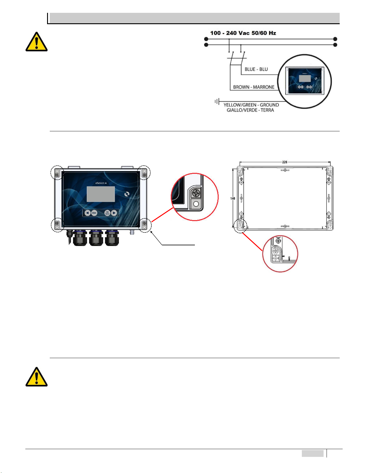
INSTALLATION
Install the instrument in a dry place, away from heat sources at
a maximum room temperature of 40°C.
Comply with standards in force in the different countries
regarding electrical installation (Fig. 2). If the power cord does not
have a plug, the device must be connected to the mains by
means of an omnipolar disconnecting switch with at least 3
mm between the contacts. All the power supply circuits must
be interrupted before accessing the connection devices.
Fig. 1 – Electrical connection
Wal l i nstal l ati on
The wall-mounting plugs are supplied with the device. Always use a plug suitable to the available support. The layout of the
holes to be drilled on the support is displayed in Figure 2.
Fig. 2 -Measurements for wall xing 226l x 146h
To access the 4 installation holes, remove the covers on the installation points (A) found on each corner of the
instrument, use a Phillips screwdriver to loosen the four screws underneath the covers, then open the front panel (see Fig.2).
The casing has 4 captive screws to quickly open/close the cover, thereby allowing for easy access for commissioning
and servicing, as well as assuring excellent seal for long-lasting operation
Install the unit in a dry place away from heat sources. Max room temperature 40°C.
Strictly comply with the regulations in force in the various countries regarding electrical systems.
Fit the instrument on the wall using the screws supplied
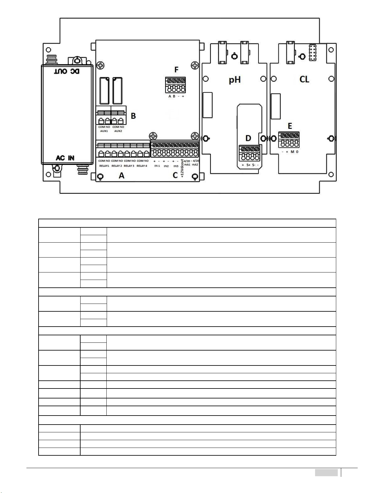
Diagram of el ectri cal connecti ons
To connect the accessories and peripheral devices to the instrument, remove the front cover screws, using a Phillips screwdriver
to reach the connecting terminal boards.
The terminal boards consist of spring terminals for quick coupling of the wires. Press the square “slotted” pin with a small at
headed screwdriver and insert the stripped wire in the corresponding terminal. ATTENTION: exert slight pressure on the spring
pin to avoid irreparably damaging the terminal board.
Do not connect more than one device to each pin
Run the wires to be connected through the cable glands on the case wall.
Covers (A) x 4
ENGLISH 11
Fig. 3 – Connection diagram
TERMINAL BOARD “A”
Relay 1 COM Setpoint 1 pH (o RX) ON-OFF / PWM output relay timed pulses
NO
Relay 2 COM Setpoint 2 pH (o RX) ON-OFF / PWM output relay timed pulses
NO
Relay 3 COM Setpoint 3 CL Chlorine ON-OFF / PWM output relay timed pulses
NO
Relay 4 COM ON-OFF ALARM relay output for external signalling device
NO
TERMINAL BOARD “B”
AUX 1 COM Auxiliary ON-OFF AUX output for remote equipment with Timer programming
NO
AUX 2 COM Auxiliary ON-OFF AUX output for remote equipment with Timer programming
NO
TERMINAL BOARD “C”
IN 1 +Digital input level probe 1 for the chemical tank
-
IN 2 +Digital input level probe 2 for the chemical tank
-
IN 3 + Proximity Sensor input BLACK wires
- Proximity Sensor input BLUE wires
+12VDC + 12 VDC output of the Proximity Sensor BROWN wire
4-20 mA1 +(+)Proportional output pH (or RX) 4-20mA1 for metering pump mA, PLC, data collection
-- (-)Proportional output 4-20mA1/mA2 for metering pump mA, PLC, data collection
4-20 mA2 +(+)Proportional output CL Chlorine 4-20mA2 for metering pump mA, PLC, data collection
TERMINAL BOARD “D”
+PT100 temperature probe (RED wire)
S + PT100 temperature probe (BLUE wire)
S - PT100 temperature probe (GREEN wire)
-PT100 temperature probe (YELLOW wire)

ENGLISH 12
TERMINAL BOARD “E”
NEW membrane Chlorine sensor Open Chlorine cell OLD membrane Chlorine sensor
-Not Connected Not Connected White Wire
+Red Wire Not Connected Brown Wire
MGrey Wire BLUE Wire Green Wire
0Black Wire Brown Wire Yellow Wire
TERMINAL BOARD “F”
AORANGE wire Connection for RS485 / ETHERNET external module.
For connection to the ETACLOUD, the external KIT CONNECT
module must be connected (NOT included with the instrument) code
KST0000101 KIT CONNECT X INSTRUMENTS SERIES M
BYELLOW wire
-BLACK wire
+Not Connected
REMEMBER: unit with universal voltage 100-250 VAC (±10%) or 9-24VDC. If the real voltage is constantly at the limit (minimum or
maximum), or when the peaks are far above the mentioned range, the unit input is electrically protected against voltage uctuations;
outside the range mentioned above, the instrument does not work and the printed circuit must be replaced. It is recommended to use
voltage protections, check the earthing system and, when other equipment is connected in parallel, use a transducer. Furthermore, ETATRON
recommends installing a UPS (genset) to assure continuity thus ensuring no data are lost. A system that is set up without following the proper
electrical design rules, without an earthing system, with frequent ON/OFF operations, might directly undermine the printed circuit.
ESELECT M2 PH(RX) - CL
Control Panel
The following figure shows the control panel with the description of the functions of the different keys.
1Button to scroll the menu to the
left and decrease values
2 Button to quit the menu
3Button to enter the menu and
conrm selections
4Button to scroll the menu to the
right and increase values
5 Display
Fig. 4 – Keypad
ENGLISH 13
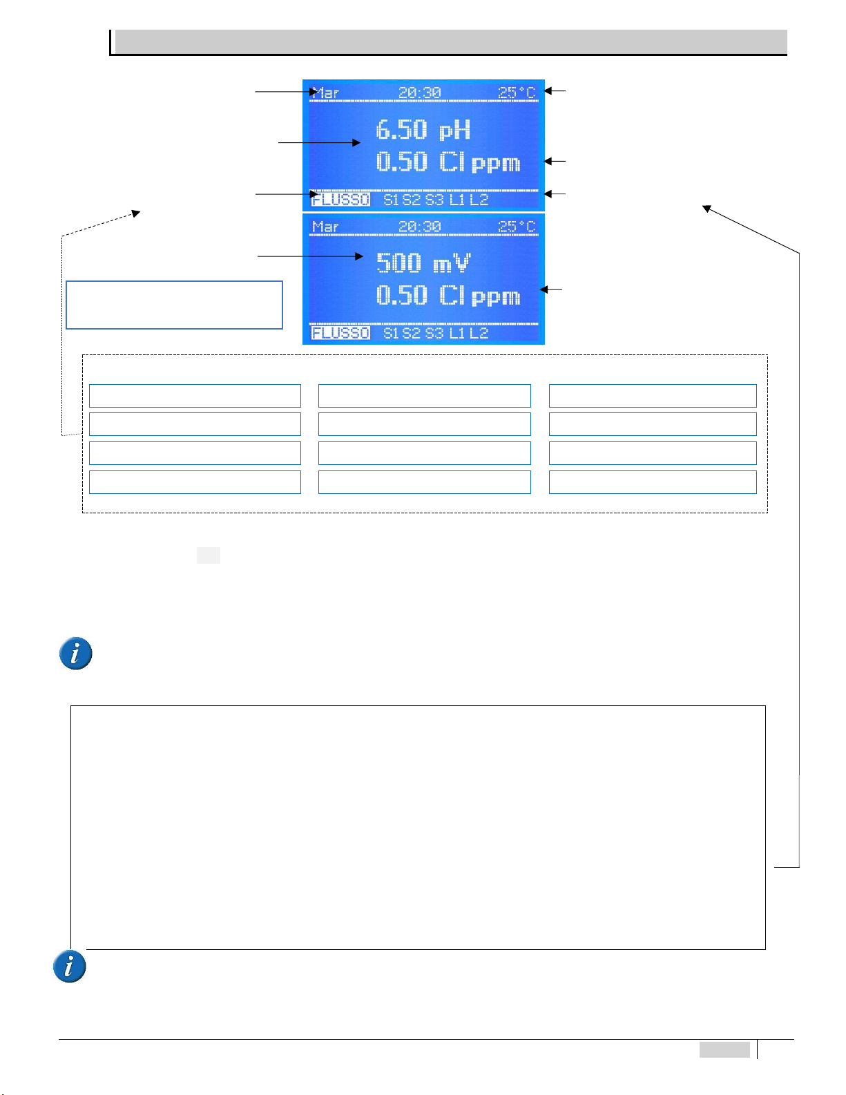
DESCRIPTION OF THE DISPLAY
* Instrument status messages shown as follows:
MAX ALARM-SETPOINT 1-3 OVERDOSE-SETPOINT 1 OVERDOSE-SETPOINT 3
MIN ALARM-SETPOINT 1-3 OVERDOSE-SETPOINT 2 AUX / DATE / TIME
FLOW OVERDOSE-4-20mA1 TEMPERATURE
NO MEASUREMENT CONN. OVERDOSE-4-20mA2 L1 L2 LEVEL MONITORING
If more than one function is active, the messages are displayed in continuous cycle, each is displayed for 3 seconds. The ALARM or
OVERDOSE message disappears once the measurements are again consistent with the programmed settings. To remove the active icons from
the display, press and hold ESC.
When the messages are displayed, the temperature value is not displayed.
NO MEASUREMENT CONNECTION LINK: communication between instrument or display down.
The software of the power and control boards of the eSelect M series are connected via the 485 protocol: when instead of the
temperature the display shows NO MEASUREMENT CONN., this means there is a problem between the two boards, in that case check
the at electric cable and immediately contact the ETATRON service.
Other status icons shown at the end of the row ***
Other status messages are as follows:
S1 S2 S3 L1 L2 ALARM AUX DATE/TIME OVERDOSE FLOW *BASIC MENU* *EXPERT MENU*
*BASIC MENU* *EXPERT MENU * these messages are displayed during the programming steps as reminders.
S1 S2 S3 indicate the corresponding active Setpoint. When the “Proportional” mode is selected (Pulse Width Modulation) during the setpoint
step, messages S1…S2 blink during PWM operation, but when the setpoint is NOT active there is no message.
** FLOW ** shows there is no water flow in the probe socket: this is only valid when using a proximity Sensor and the “Flow Sensor” (step in
Settings) is on, only possible by using the Expert Menu.
L1 L2 indicates level control of an external tank and is only shown once the level probe is connected to the pins of terminal IN1 and IN3: when
the level in the tank is lower than the float of the level probe, it triggers the Status message.
When the instrument is rst switched on, a list of all key programming functions is displayed.
Temperature value: if the temperature has been set up in manual mode, the temperature value matches the one selected. If the PT100 mode
has been selected and a temperature sensor has been connected, the temperature value shown matches the real value in the system and
allows for automatic offsetting.
NOTE: when working with the Basic menu, the mA programming IS NOT AVAILABLE:
Temperature value**
Status of the instrument
PH measurement
Other status icons***
Backlit display (126x64)
Visible display area 70x37 mm
RX measurement (Redox)
Date / Time
Chlorine Value
Chlorine Value

ENGLISH 14
OPERATING FUNCTIONS
ON-OFF m ode
The unit has an ON-OFF mode which switches on (or off if the reverse mode is ON) the output relays to control Constant / ON-OFF
metering pumps, peristaltic pumps or other ON-OFF equipment.
DIR ECT / REVERSE di rection
The setpoint relays are factory set as follows:
Setpoint 1 PH: ACID mode, the output is active when the measured value is higher than the selected setpoint, the connected pump
meters out an acid product.
Setpoint 2 PH: ALKALINE mode, the output is active when the measured value is lower than the selected setpoint, the connected
pump meters out an alkaline product.
Setpoint 1 RX: DIRECT mode, the output is active when the measured value is lower than the selected setpoint, the connected
pump meters out an Oxidising product.
Setpoint 2 RX: REVERSE, the output is active when the measured value is higher than the selected setpoint, the connected pump
meters out a reducing product.
Setpoint 3 CL: DIRECT mode, the output is active when the measured value is lower than the selected setpoint. REVERSE mode,
the output is active when the measured value is higher than the selected setpoint.
ALARM MI N / MAX function
The Alarm function makes it possible to select the minimum and maximum values outside which the instrument goes into alarm
mode.
HYSTERESI S
Hysteresis is useful during operations to adjust the setpoints in ON-OFF mode and is used to enable or disable the output relays
when the selected hysteresis has been achieved. Hysteresis is useful when there are too many quick swings around the setpoint, that might
damage the connected device. By increasing hysteresis it is possible to move away from the setpoint in accordance with the required value.
Example PH: if the selected set point is 7.00 pH and hysteresis is set at 0.05, the two active points are 6.95 pH and 7.05 pH: within this
range, the set point is OFF and the outputs are blocked, outside this range the set point is ON (always in accordance with Acid or alkaline mode).
The RX parameter (mV) works in the same way indicating values in mV. The chlorine measurement CL works according to the values for the
selected chlorine range showing values in ppm.
DELAY output response delay on set point
The Delay time blocks the output relays (max 999 sec. programmable) to ensure the outputs are active only when the sensor
measurements are stable, thus assuring the best results in terms of chemical balance.
PROPOR TIONAL PWM m ode: Timed “Pul se Width Modul a tion”
PWM “pulse width modulation” support a proportional mode on each ON-OFF setpoint activating at the pulse, with a change of the
Start/Stop cycle time according to the measured value with respect to the setpoint.
Pulse width: pulses are timed ON and OFF based on the distance from the selected setpoint, programmable, example: if the selected
setpoint is 7.00 pH and the measured value is 9.00 pH, if the selected value of the PWM mode is 1.50 pH, the proportional function starts
after reaching 8.50 pH with Time/Pause pulses and decreasing the active time while reaching the setpoint.
Cycle Time: selected value of the PWM mode 1.50 pH with a 60 second cycle (programmable), example: setpoint is 7.00 pH, at
measured value 8.50 pH = active time 60 sec - pause time = 0 sec; 7.75 pH active time = 30 sec - pause time = 30 sec… decreasing the
active time as a consequence while reaching the setpoint. The cycle time depends on many variables, such as: distance from the injection
point of the system to be treated, how fast or slowly the setpoint needs to react, chemical concentration, etc.
MIN Active Time: programmable. Defines the minimum time for which PWM is active; prevails over the selected settings. The pulse
modulation function is adjusted with 3 functions according to the following formula: Active Time in accordance with the selected formula =
(measured value - setpoint) / (period width * cycle time). If the result of the formula is <than that chosen with MIN Active Time, the latter
prevails on the former, example: measured value 8.50 pH; setpoint 7.00 pH / Period Width 1.50 * Cycle time 60 sec = active time 4 sec. If the
user has selected Active time min 5 sec, this will be the minimum PWM time and not 4 sec.
The RX parameters (mV) work in the same way indicating values in mV.

ENGLISH 15
The chlorine measurement CL works according to the corresponding values relating to the selected chlorine range indicating the
value in Cl ppm.
ADVANTAGES: the proportional function is more accurate than the ON-OFF mode.
DISADVANTAGES: the user needs to be a professional in order to select the most accurate settings to assure the best results.
ANA LOGUE O UTPU TS I N CURRE NT 4 -2 0 mA1 / 4-20 m A2
The instrument features 2 outputs with signal in current in mA. The 4-20 mA signal follows the pH or RX mV and CL (ppm) settings
previously selected. The mA output provides two operating modes to be selected according to the system requirements:
mA DEVICE: this is a programmable function combined with the unit of measure of the pH or RX and CL measurement in real time which
makes it therefore possible to remotely monitor devices such as data loggers, PLCs, recorders or other devices suited to processing remote
signals in mA.
Value 4 mA corresponds to the minimum programmed pH or RX mV or CL (ppm) value, 20 mA corresponds to the maximum measurable
pH or mV and CL value, the connected equipment will operate accordingly.
METERING ON SETPOINT: mA outputs control metering pumps suited to processing an input mA signal.
4 mA corresponds to the minimum pH or RX mV and CL (ppm) value, hence the connected metering pumps will work at their minimum
capacity. 20 mA corresponds to the maximum measured pH or RX mV or CL value hence the connected metering pump will work at its
maximum programmed capacity (according to the settings of the device and of the metering pump).
ADVANTAGES: best possible results because the pulses are extremely accurate in relation to measured levels.
DISADVANTAGES: the user requires a specic metering pump or other device suited to processing a remote signal in mA.
OVERDO SE TIME
With the overdose time alarm one can select a period during which the setpoint must be reached. If the setpoint is not reached
during this period of time, the instrument blocks output operations, including those in mA (metering pumps), the alarm is displayed as ON
and triggers a signalling instrument if it is connected to the alarm relay.
ADVANTAGES: preventing excessive doses of chemicals.
MAXIMUM METERING TIME
The maximum metering time is an extra function that ensures that metering operations are completed within a certain time limit
selected by the operator. The relays connected to the metering pumps activate accordingly. This function makes it possible to eliminate time
limits, to meter continuously based on the selected setpoints or, if the operator wishes to change the settings, to choose a given period (up to
999 minutes) within the selected hours.
ADVANTAGES: preventing excessive addition of chemical product not only according to the setpoint, but also cancelling any form of
programming of the instrument’s setpoint.
TI MER I N R EA L T IM E / ST AR T -S TOP T IM E
The Timer in real time makes it possible to control through a timer the AUX outputs for each remote device for the period selected in
the program. The operator may also program the days of activity and the exact time of the unit’s operations through the Start/Stop
programming.
AUX OUTPUTS
The two AUX auxiliary outputs control various functions connected to any type of remote On-Off device controlled by a timer in real
time. Each output may control a device or appliance thanks to very accurate programming of minutes/hours/days/weeks.
ADVANTAGES: this function makes this instrument a very versatile control unit not only to measure chemical physical parameters but also for
other functions connected to the system where it is installed.
START-UP DELAY
The start-up delay blocks the output relays when the unit is switched on, thus allowing the sensor to polarise assuring correct
measurements (programmable).
FLOW SENSO R function “Proximi ty Sensor”
Flow Sensor (not included): if there is no water flow in the probe socket (and possibly in the system), the flow sensor (proximity
sensor) disables all outputs ensuring no chemical substance is added.
ENGLISH 16
TEMPERATURE
Manual / Automatic Temperature offset (the latter with a temperature sensor) 0-100°C, the temperature / conductivity measurements
will be offset, always obtaining the exact value against the current temperature.
ETHERNET / RS485 external comm unication module
The eSelect M series is suitable for remote control thanks to an RS485 expansion board with Modbus protocol using the ETACLOUD
software. The ETHERNET connection allows the operator to connect to the unit via a PC, a smartphone or a tablet and change the
programming and settings using the ETACLOUD software. The unit sends a message once the alarm level, overdose settings are reached,
or when the maximum metering time of the metering pump has elapsed.
INITIAL DISPLAY
NOTE FOR THE PROGRAMMER: Read the manual before starting programming or always have it at hand to be sure you are making the
correct selections.
IMPORTANT: if no keys are pressed for 60 seconds, the instrument will show the current measurement.
To go forward quickly, press and hold one of the ◄► buttons
The software version is shown when the instrument is on the lower part of the display.
The software is subject to revisions without notice.
The instrument is prepared for measuring and is then ready to operate.
At this stage some status messages might be displayed, such as: S1 S2 S3 L1 L2 ALARM AUX DATE/TIME OVERDOSE
FLOW *BASIC MENU* *EXPERT MENU*, which might be active due to current measurements, just go forward with the
programming.
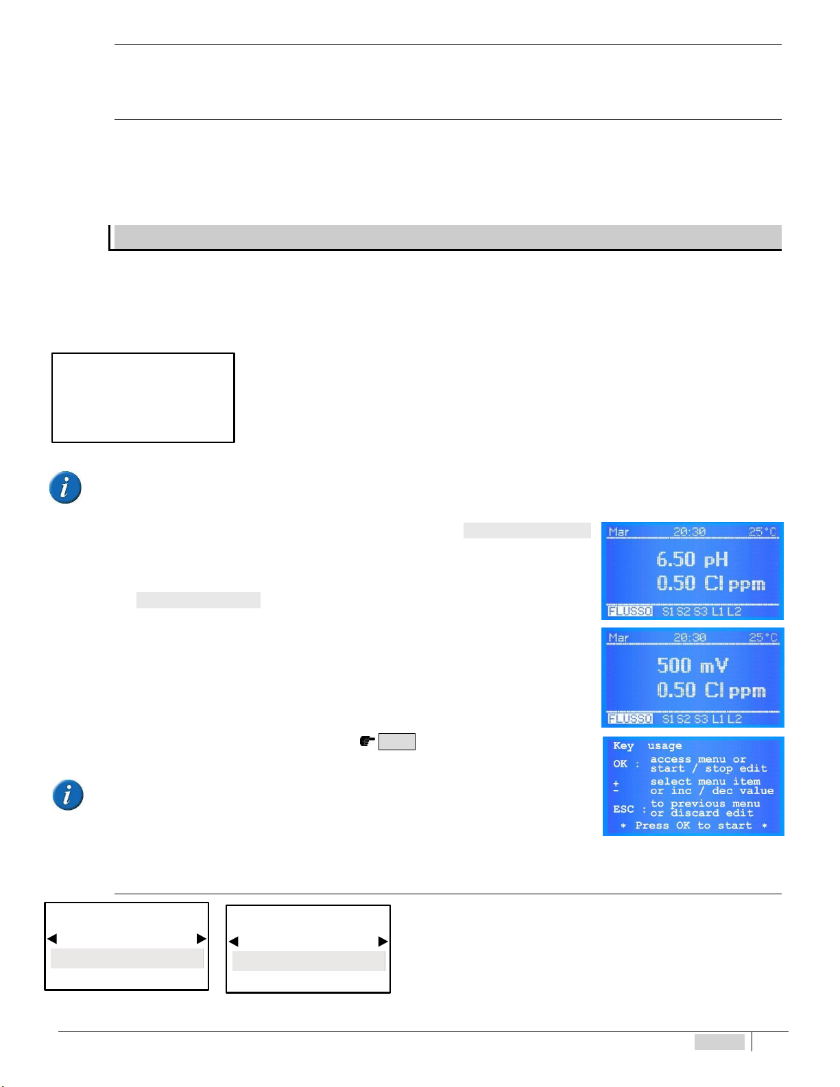
The INITIAL DISPLAY shows the measurements according to the selected M e as ure me nt Ty pe
(SELECT MEASUREMENT TYPE PH OR RX and SELECT THE CHLORINE RANGE). If the instrument has
already been programmed, the display shows the programs selected previously.
NOTE: if the RX M ea sur em ent Ty pe is selected, all values are automatically changed to mV.
The CONTINUOUS MEASUREMENT DISPLAY shows the measurements of the parameter, the status of the
functions and the alarm indications.
When the instrument is switched on for the first time, a list of functions of all keys is displayed. This screen
is no longer displayed during subsequent start-up operations.
READ THE MESSAGE CAREFULLY, THEN PRESS O K KTO START.
USE OF THE KEYS
OK: access to the menu, start/stop, selection and editing
selects the step of the menu or increases / decreases the value
ESC: goes back to the previous menu or does not save the change
* Press OK to start*
To go forward quickly, press and hold one of the ◄ ►buttons IN ENGLISH
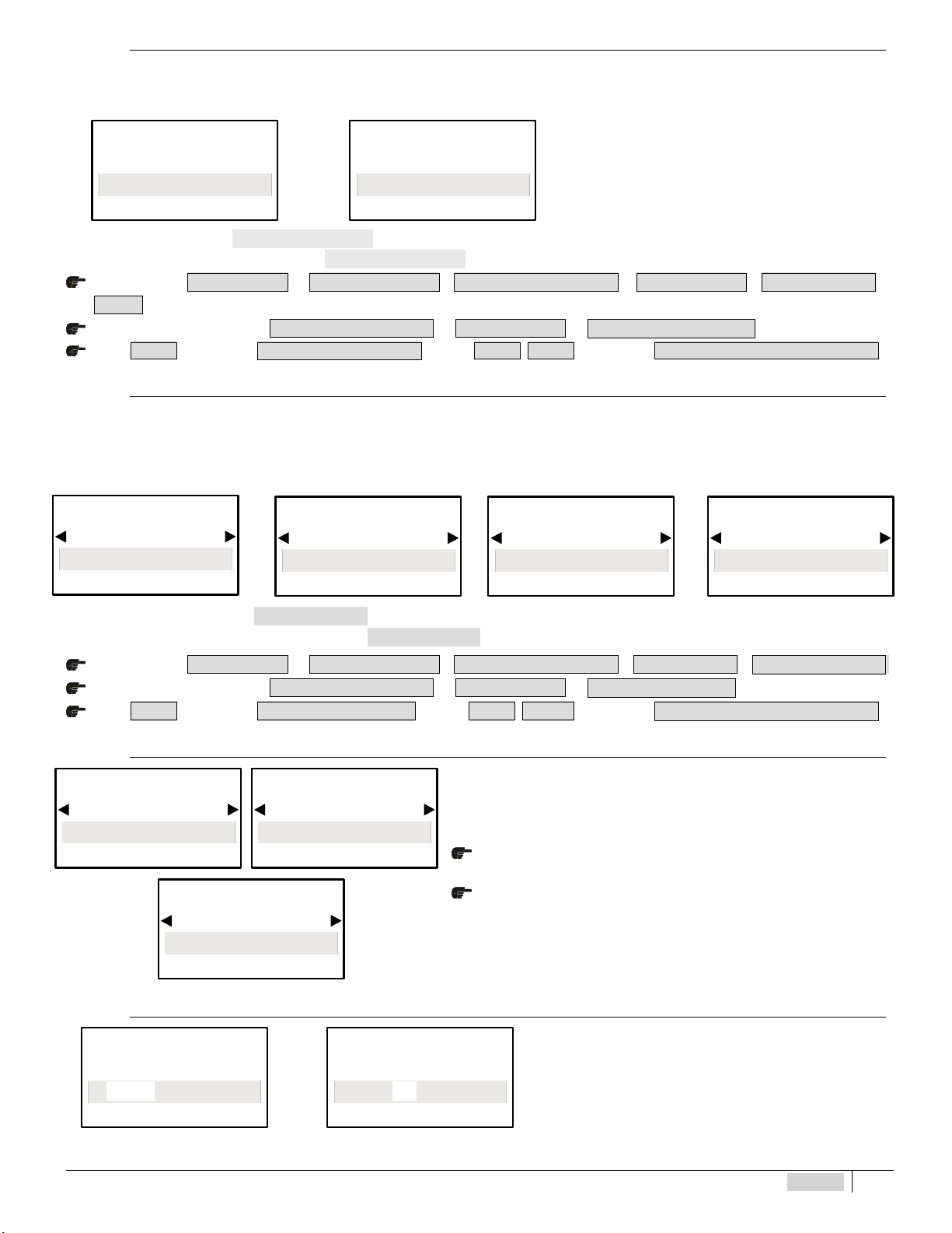
Select the language of th e PROGRAMMIN G MENU
To select the language of the programming menu.
After selecting the Language (ITALIAN, ENGLISH), the programming menu
adapts accordingly.
ETATRON
Model eSelec M2
Rev. X. X
CONTROLLER SETTINGS
Language
English
BASIC MENU
SETTINGS
Lingua
Italiano
MENU BASE
ENGLISH 17
Select MEASUREMENT TYPE PH or RX
The instrument of the eSelect M2 series makes it possible to select the type of measurement to be used, i.e. PH or RX (Redox) in the
same unit. The measurement parameter may be changed from PH to RX and the display and resolutions of the measurement change
accordingly.
◄ ►◄ ► By selecting one of the two types of measurement,
programming of the main Menu changes accordingly.
IMPORTANT: after selecting M ea sureme nt T ype PH or RX, ENSURE you connect the appropriate electrode.
In case the operator should want M e asu reme nt T ype also during operations, proceed as follows:
BASIC menu > S E T T I N G S > M E N U E X P E R T > M E N U S E L E C T I O N > S E T P O I N T 1 > Me a s u r e m e n t
Ty p e a
from EXPERT menu go into > M E N U S E L E C T I O N > S E T P O I N T 1 > M e a s u r e m e n t T y p e a
Press E S C to go back to M E N U S E L E C T I O N or press E S C E S C to go back to M E A S U R E M E N T D I S P L A YA
Select the CHLO RINE Measurem ent RANGE
The instrument eSelect M2 PH(RX)-CL offers the option of selecting 4 chlorine measurement ranges and related sensors:
-Ion-selective membrane sensors with measurement ranges 0-2 Cl ppm (preset); 0-20 Cl ppm; 0-20 Cl ppm (Total Chlorine);
-Open type amperometric cell (model CLC) range 0-10 Cl ppm
After making the selection, the measurement parameters displayed will change accordingly.
IMPORTANT: after selecting the CHLORINE SCALE,ENSURE the adequate chlorine sensor is connected.
In case the user should wish to change the range via CHLORINE SCALE, even during operations:
BASIC menu > S E T T I N G S > E X P E R T M E N U > M E N U S E L E C T I O N > S E T P O I N T 1 > C h l o ri n e S c a l e o
from EXPERT menu go into > M E N U S E L E C T I O N > S E T P O I N T 1 > SC h l o ri n e S c al e o
Press E S C to go back to M E N U S E L E C T I O N or press E S C E S C to go back to M E A S U R E M E N T D I S P L A Y A
TEMPERATURE settings
Manual temperature offset 0-100°C.
Press ◄► to change the ambient temperature.
Select AUTOMATIC offsetting for measurements and temperature
offsetting with PT100 sensor.
DATE AND TIME – TIMER i n REAL TIME
◄ ►◄ ► Program the date and time by selecting the backlit steps.
Measurement Type
pH
Measurement Type
Rx
SETTINGS
Chlorine Scale
Cl 0-2 ppm
MENU BASE
SETTINGS
Chlorine Scale
Cl 0-20 ppm
MENU BASE
SETTINGS
Chlorine Scale
Cl Tot
MENU BASE
SETTINGS
Chlorine Scale
CLC (0-10 ppm)
MENU BASE
SETTINGS
Temp. Sensor
Automatic
SETTINGS
Temperature
25°C
SETTINGS
Temp. Sensor
Manual
Date
2014 May 14
Time
12:02

ENGLISH 18
PROGRAMMI NG MENU
The instrument lets you choose between two programming modes:
BASIC programming: simplified mode for non-professional operators.
EXPERT programming: complete programming that includes functions for more accurate control and results.
After selecting the type of programming, the Menus and sub-menus change accordingly.
To help the operator choose the correct menu, the main differences between the two menus are set out below:
Setpoint 1 -2-3 <Set poi nt value - Meteri ng - ON/OFF or Proport i onal m ode – MIN /MAX Alarm (only
on Setpoint 1-3) > Calibration > Setti ngs >
Setpoint 1 -2-3 < Setpoint value - Meteri ng - ON /OFF or Proportional m ode - Hysteresis - Set point
delay - Temp. correcti on - MIN /MAX Alarm (only on Setpoint 1 -3) - Ove rdose - Max Dosage – Start-
up delay > 4-20m A1 > 4-20mA2 > Cali brati on > Start/Stop > Au x Output > Settings >
Press O K / M E N U
the
display shows BASIC menu (default)
MAIN MENU > BASIC PROGRAMMING MENU
These are all the steps included in the Main menu configuration with the BASIC programming menu:
◄ ► ◄ ► ◄ ►
*When M e a s u r e m e n t T y p e RX,
SS E T P O I N T 1 , S E T P O I N T 2 and
CC A L I B R A T I O N are selected, readings will
be RX (mV )
*Selecting the setting C h l o r i n e S c a l e ,
S E T P O I N T 3 and C A L I B R A T I O N will be
followed by values in the selected Cl ppm range
◄ ► ◄ ► ◄ ►
◄ ►
Press O K / M E N U to conrm the selection and to go to the next sub-menu.
Press E S C to go back to the M E A S U R E M E N T D I S P L A Y
SETPOINT 1 PH AND SETPOINT 1 RX > BASIC MENU
SETPOINT1 PH SETPOINT1 RX
The two programming stages are set out below: when Measurement Type
pH is selected, refer to the left column; when selecting RX refer to the right
column.
The setpoints activate the output relays for the metering pumps or other
devices until the setpoint is reached.
Menu Mode
BASIC
Menu Mode
EXPERT
Menu Selection
Setpoint 1(pH)*
Menu Selection
Setpoint 2 (pH)*
Menu Selection
Setpoint 3 (Cl)**
Menu Selection
Calibr at.M1(pH)*
Menu Selection
Calibr at.M2(Cl)**
Menu Selection
Start/S top times
Menu Selection
Settings
Menu Selection
Setpoint 1 (pH)
Menu Selection
Setpoint 1 (RX)
MENU SETPOINT 1 (pH)
Setpoint Value
7.00 pH
MENU BASE
MENU SETPOINT 1 (RX)
Setpoint Value
200 mV
MENU BASE
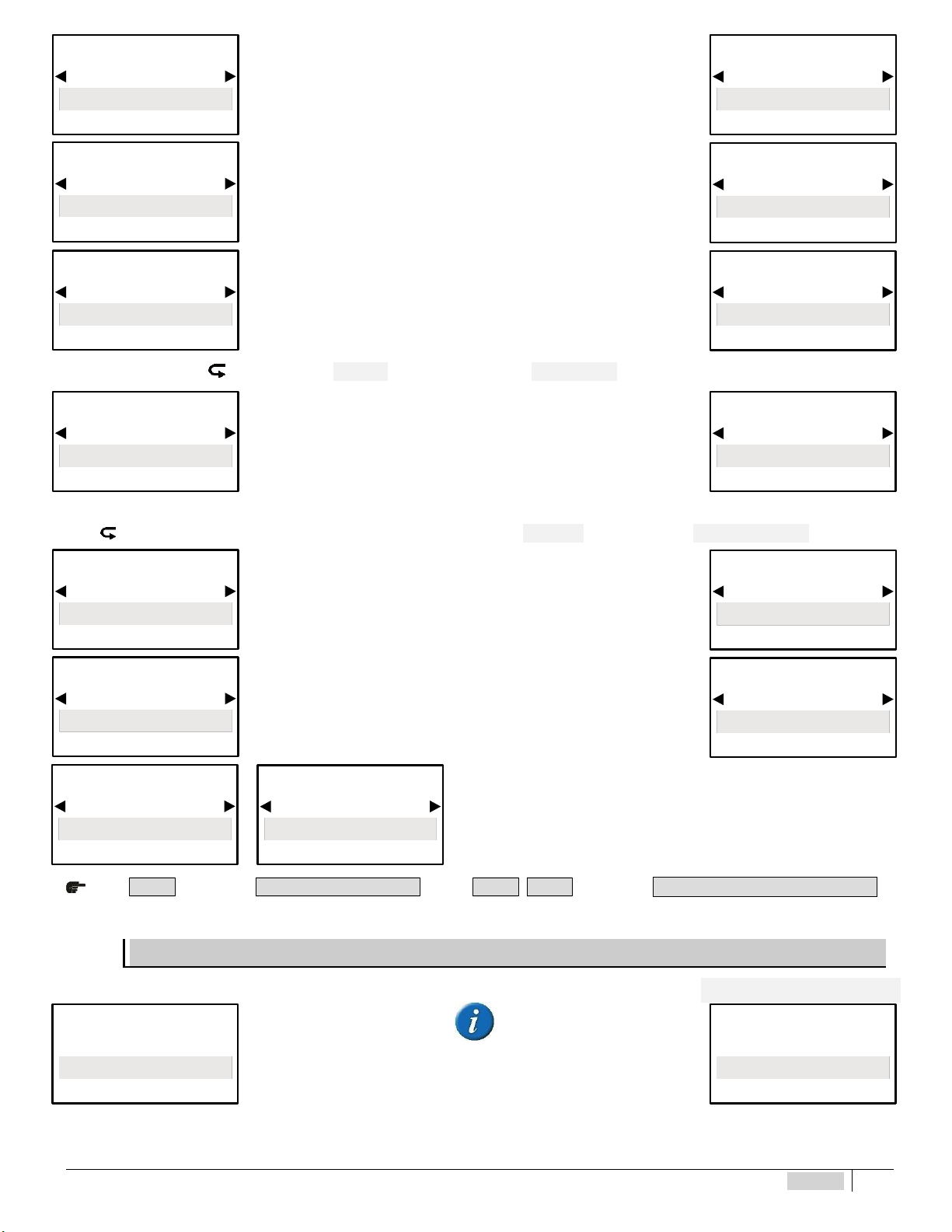
ENGLISH 19
Setpoint 1 is set for operations in
ACID mode, the output is active
when the measured value is higher
than the selected setpoint, the
connected pump meters out an acid
product.
Setpoint 1 is set for operations in
DIRECT mode: if the measured
value is lower than the selected
setpoint, the connected pump
meters out an oxidising product.
The unit has an ON-OFF mode which switches on or off (if the reverse mode
is ON) the output relays of Constant / ON-OFF metering pumps or other ON-
OFF equipment.
BY SELECTING “ON-OFF” THE NEXT STEP IS “MIN ALARM” (ONLY SET POINT1)
*Modular pulses, also known as PWM “pulse width modulation”, support a
proportional mode on each setpoint, activating the corresponding pulses on
the relays based on the measured value.
Default activation point 1.50 pH
Default activation point 150 mV
For more accurate settings of the “Modular pulses” PWM, select the “Expert” menu in the initial settings.
*GOING BACK TO THE SETPOINT PROGRAMMING STEPS FROM “ON-OFF” MODE OR FROM “PROPORTIONAL” MODE
The MIN Alarm function selects a MINIMUM alarm level, after which the
alarm relay is triggered.
The MAX Alarm function selects a MAXIMUM alarm level, after which the
alarm relay is triggered.
The priming function blocks the setpoint value to allow the metering pump to
remain primed.
Press E S C to go back to M E N U S E L E C T I O N or press E S C E S C to go back to M E A S U R E M E N T D I S P L A Y A
SETPOINT 2 PH AND SETPOINT 2 RX > BASIC MENU
SETPOINT2 PH SETPOINT2 RX
The two programming stages are below: when Measurement Type pH is
selected, refer to the left column; when selecting RX refer to the right
column.
MENU SETPOINT 1 (pH)
Metering
Acid
MENU BASE
MENU SETPOINT 1 (RX)
Metering
Direct
MENU BASE
MENU SETPOINT 1 (pH)
Metering
Alkaline
MENU BASE
MENU SETPOINT 1 (RX)
Metering
Reverse
MENU BASE
MENU SETPOINT 1 (pH)
Mode
ON/OFF
MENU BASE
MENU SETPOINT 1 (RX)
Mode
ON/OFF
MENU BASE
MENU SETPOINT 1 (pH)
Mode
Proportion al
MENU BASE
MENU SETPOINT 1 (RX)
Mode
Proportional
MENU BASE
MENU SETPOINT 1 (pH)
MIN Alarm
0.00 pH
MENU BASE
MENU SETPOINT 1 (RX)
MIN Alarm
–1500 mV
MENU BASE
MENU SETPOINT 1 (pH)
MAX Alarm
14.00 pH
MENU BASE
MENU SETPOINT 1 (RX)
MAX Alarm
1500 mV
MENU BASE
MENU SETPOINT 1 pH / RX
Priming
OFF
MENU BASE
MENU SETPOINT 1 pH / RX
Priming
ON
MENU BASE
Menu Selection
Setpoint 2 (pH)
Menu Selection
Setpoint 2 (RX)
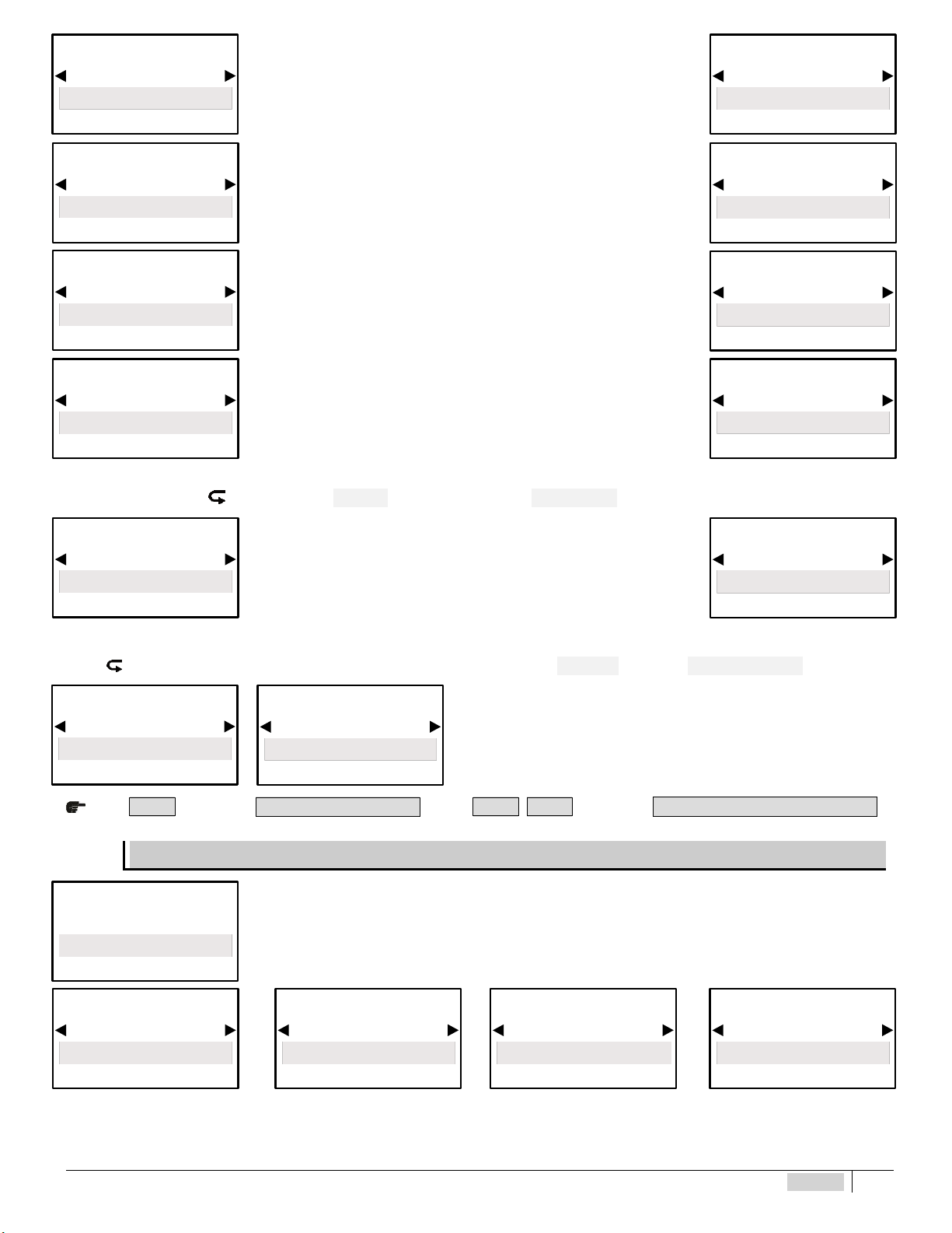
ENGLISH 20
The setpoints activate the output relays for the metering pumps or other
devices until the setpoint is reached.
Setpoint 2 is set for operations in
ALKALINE mode, the output is
active when the measured value is
lower than the selected setpoint, the
connected pump meters out an
alkaline product.
Setpoint 2 is set for operations in
REVERSE mode: if the measured
value is higher than the selected
setpoint, the connected pump
meters out a reducing agent.
The unit has an ON-OFF mode which switches on or off (if the reverse mode
is ON) The output relays of Constant / ON-OFF metering pumps or other
ON-OFF equipment.
BY SELECTING “ON-OFF” THE NEXT STEP IS “MIN ALARM” (ONLY SET POINT1)
*Modular pulses, also known as PWM “pulse width modulation”, support a
proportional mode on each ON-OFF setpoint, activating the corresponding
pulses on the relays based on the measured value (see pg.11-12).
Default activation point 1.50 pH
Default activation point 150 mV
For more accurate settings of the “Modular pulses” PWM, select the “Expert” menu in the initial settings.
*GOING BACK TO THE SETPOINT PROGRAMMING STEPS FROM THE “ON-OFF” MODE OR “PROPORTIONAL” MODE
The priming function blocks the setpoint value to allow the metering pump to
remain primed.
Press E S C to go back to M E N U S E L E C T I O N or press E S C E S C to go back to M E A S U R E M E N T D I S P L A Y A
SETPOINT 3 CL CHLORINE > BASIC MENU
The instrument is preset by default for a 02 ppm range. By selecting the required chlorine range, the values
displayed change accordingly. The setpoints will activate the output relays for the metering pumps or other
devices once the setpoint level is selected.
The display shows the values according to the selected Chlorine Scale.
MENU SETPOINT 2 (pH)
Setpoint Value
7.00 pH
MENU BASE
MENU SETPOINT 2 (RX)
Setpoint Value
200 mV
MENU BASE
MENU SETPOINT 2 (pH)
Metering
Alkaline
MENU BASE
MENU SETPOINT 2 (RX)
Metering
Reverse
MENU BASE
MENU SETPOINT 2 (pH)
Metering
Acid
MENU BASE
MENU SETPOINT 2 (RX)
Metering
Direct
MENU BASE
MENU SETPOINT 2 (pH)
Mode
ON/OF F
MENU BASE
MENU SETPOINT 2 (RX)
Mode
ON/OF F
MENU BASE
MENU SETPOINT 2 (pH)
Mode
Proportion al
MENU BASE
MENU SETPOINT 2 (RX)
Mode
Proportional
MENU BASE
MENU SETPOINT 2 pH / RX
Priming
OFF
MENU BASE
MENU SETPOINT 2 pH / RX
Priming
ON
MENU BASE
Menu Selection
Setpoint 3 (Cl)
MENU SETPOINT 3 (Cl)
Setpoint Value
0.000 Cl ppm
MENU BASE
MENU SETPOINT 3 (Cl)
Setpoint Value
0.00 Cl ppm
MENU BASE
MENU SETPOINT 3 (Cl)
Setpoint Value
0.00 Cl ppm * (Tot )
MENU BASE
MENU SETPOINT 3 (Cl)
Setpoint Value
0.00 Cl ppm
MENU BASE
This manual suits for next models
1
Table of contents
Other Etatron Measuring Instrument manuals


Popular Measuring Instrument manuals by other brands


Lovato
Lovato DME D330 installation manual

Bürkert
Bürkert 8025 Series operating instructions

Seko
Seko KMG Series installation manual

HEIDENHAIN
HEIDENHAIN ERA 4201 Mounting instructions

GW Instek
GW Instek GLP-1A Operator's manual

Absolute Process Instruments
Absolute Process Instruments Cecomp DPG2000B Series instructions