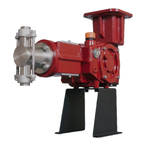
TKM K Series User manual

K SERIES
HYDRAULIC
DIAPHRAGM
PUMP
KH Pump Installation and Operating
Instructions Manual
TKM LLC
1059 Triad Court, Suite 1
Marietta, GA, USA, 30062
+1 (770) 943-4922

TKM K Series Metering Pumps Operation Manual
KH OM v.1.8 Copyright © 2018 TKM LLC All Rights Reserved 2
Table of Contents
1. INTRODUCTION TO TKM K SERIES METERING PUMPS ................................................................ 5
1.1 DESCRIPTION OF TERMS................................................................................................................................................ 5
1.2 GENERAL INFORMATION................................................................................................................................................ 5
2. SAFETY INSTRUCTIONS AND GUIDELINES..................................................................................... 6
2.1 QUALIFIED PERSONNEL AND TRAINING ...................................................................................................................... 6
2.2 SAFETY PRECAUTIONS DURING MAINTENANCE,SERVICING,AND INSTALLATION................................................. 7
2.3 NEGLECTING THE SAFETY INSTRUCTIONS.................................................................................................................... 7
2.4 IMPORTANCE OF TKM AUTHORIZED SPARE PARTS................................................................................................... 7
2.5 INTENDED USE FOR THE TKM PUMP........................................................................................................................... 7
2.6 PERSONAL PROTECTION EQUIPMENT FOR INSTALLATION AND MAINTENANCE.................................................... 8
3. MANUFACTURER’S WARRANTY...................................................................................................... 8
4. GENERAL DESCRIPTION OF TKM K SERIES HYDRAULIC DIAPHRAGM PUMP............................ 9
4.1 KH HYDRAULIC DIAPHRAGM PUMP MODELS............................................................................................................ 9
4.1.1 The Standard KH Pump.....................................................................................................................................10
4.1.2 The High Viscosity KH Pump...........................................................................................................................10
4.1.3 The Double Diaphragm KH Pump.................................................................................................................11
4.2 KH HYDRAULIC DIAPHRAGM PUMP STANDARD FEATURES ...................................................................................12
5. RECEIVING AND STORING A TKM PUMP ..................................................................................... 13
5.1 RECEIVING INSPECTION................................................................................................................................................13
5.2 STORING A TKM PUMP...............................................................................................................................................13
6. TECHNICAL DATA............................................................................................................................ 14
6.1 SPECIFICATIONS ............................................................................................................................................................14
6.2 KH PUMP DIMENSIONS...............................................................................................................................................15
6.3 TEMPERATURE...............................................................................................................................................................15
6.3.1 Temperature Ratings for PVC KH Pump and PVDF KH Pump............................................................15
6.3.2 Temperature Ratings for Stainless Steel KH Pump..................................................................................15
6.4 NOISE LEVELS................................................................................................................................................................16
6.5 PUMP NAME PLATE NOTATION .................................................................................................................................16
6.6 KH STANDARD COMPONENTS ...................................................................................................................................18
6.7 KH HYDRAULIC OIL......................................................................................................................................................18
7. INSTALLATION ................................................................................................................................ 19
7.1 MOUNTING A TKM PUMP ..........................................................................................................................................19
7.2 CONNECTING THE SUCTION PIPING...........................................................................................................................19
7.2.1 Suction Line Filters..............................................................................................................................................21
7.3 CONNECTING THE DISCHARGE PIPING ......................................................................................................................22
7.3.1 Pressure Relief Valve ..........................................................................................................................................23
7.3.2 Pulsation Dampener...........................................................................................................................................23
7.3.3 Back Pressure Valve or Anti-Siphoning Mechanism................................................................................24
7.4 RECOMMENDED CONFIGURATION FOR TKM KH PUMP SYSTEM .........................................................................25

TKM K Series Metering Pumps Operation Manual
KH OM v.1.8 Copyright © 2018 TKM LLC All Rights Reserved 3
25
7.5 FLUSHING THE LIQUID END.........................................................................................................................................26
8. PUMP COMPONENTS ..................................................................................................................... 26
8.1 THE GEAR BOX..............................................................................................................................................................26
8.2 STROKE LENGTH ADJUSTMENT...................................................................................................................................26
8.2.1 Adjusting the Stroke Position ..........................................................................................................................27
8.3 THE LIQUID END ...........................................................................................................................................................28
8.3.1 The Check Valves.................................................................................................................................................28
8.3.2 The KH Plunger and Diaphragm ...................................................................................................................30
8.3.3 The KH Safety Valve...........................................................................................................................................30
8.3.4 The KH Air Bleed Valve .....................................................................................................................................31
8.3.5 Replacement Parts and Repair Kits...............................................................................................................32
8.3.6 Repair Kit Contents.............................................................................................................................................33
8.4 THE ELECTRIC MOTOR .................................................................................................................................................38
8.4.1 Configuring the Electric Motor........................................................................................................................38
9. STARTUP .......................................................................................................................................... 39
9.1 STARTING A TKM PUMP .............................................................................................................................................39
10. SERVICING A TKM KH PUMP..................................................................................................... 40
10.1 REBUILDING THE CHECK VALVES ................................................................................................................................41
10.1.1 Removing the Guides and Seats (Stainless Steel Liquid End)..........................................................41
10.1.2 Removing the Guides and Seats (PVC and PVDF Liquid End) ........................................................41
10.1.3 Replacing the Guides and Seats (Stainless Steel Liquid End)...........................................................41
10.1.4 Replacing the Guides and Seats (PVC and PVDF Liquid End).........................................................42
10.2 REPLACING THE KH DIAPHRAGM...............................................................................................................................43
10.3 REPLACING THE KH DOUBLE DIAPHRAGM ...............................................................................................................45
10.4 CHANGING THE HYDRAULIC FLUID ............................................................................................................................45
10.5 TROUBLESHOOTING THE TKM KH PUMP .................................................................................................................46
10.6 RETURNING THE TKM PUMP FOR REPAIRS...............................................................................................................48
10.6.1 Preparing the TKM Pump for Returns .....................................................................................................49
10.6.2 RMA for TKM Pump Return.........................................................................................................................49
11. CONTACTING TKM LLC............................................................................................................... 50

TKM K Series Metering Pumps Operation Manual
KH OM v.1.8 Copyright © 2018 TKM LLC All Rights Reserved 4
Table of Figures
Figure 1 - Electrically triggered Diaphragm Rupture Indicator on a PVC KH35 Pump ...................12
Figure 2 - KH Pump dimensions..........................................................................................................................15
Figure 3 - Avoid irregular piping when connecting the suction line .....................................................20
Figure 4 - Avoid debris from bottom of reservoir tank ..............................................................................20
Figure 5 - Avoid rounded tubing in suction line to prevent air in suction line..................................21
Figure 6 - Always run piping through walls or barriers ..............................................................................21
Figure 7 - Correctly integrating a Y-strainer on the suction line.............................................................22
Figure 8 - Using a foot valve with a strainer when suction line runs into reservoir tank ...............22
Figure 9 - Pressure relief valve and recycling line.........................................................................................23
Figure 10 - Pulsation dampener and back pressure valve.........................................................................24
Figure 11 - Using a back pressure valve to avoid unwanted siphoning...............................................25
Figure 12 - Recommended configuration for TKM Pump system ..........................................................25
Figure 13 - The adjustment knob reading approximately 25% flowrate..............................................28
Figure 14 - Correct orientation for discharge valve assembly..................................................................42
Figure 15 - Correct orientation for suction valve assembly ......................................................................42
Figure 16 - Correct orientation for suction valve assembly ......................................................................43
Figure 17 - Correct orientation for discharge valve assembly..................................................................43
Figure 18 - KH Standard Pump Liquid End......................................................................................................44
Figure 19 - Oil plug locations...............................................................................................................................45
Copyright Notice
This Operating Instructions Manual and all the technical information provided is
property of TKM LLC. This document is protected by U.S. and International copyright
laws. Reproduction, modification, or distribution of the manual without written
permission from TKM LLC is prohibited.
Copyright © 2016-2018 TKM LLC All Rights Reserved

TKM K Series Metering Pumps Operation Manual
KH OM v.1.8 Copyright © 2018 TKM LLC All Rights Reserved 5
1. Introduction to TKM K Series Metering Pumps
This instruction manual is for the purpose of providing the end user with an extensive
understanding of TKM Metering Pumps. The information provided in these instructions
includes important guidelines for the safe and successful installation, operation, and
maintenance of TKM K Series Hydraulic Diaphragm Metering Pumps.
The instructions and additional information outlined in this document must be integrated into
the current rules and regulations in the location of installation. The instructions in this manual
DO NOT replace any company or plant regulations or requirements which have been issued for
safety purposes.
1.1 Description of Terms
In order to prevent ambiguity and possible misinterpretation of information, the following
technical description of users and personnel have been defined and assigned a common term,
which will be referred to hereafter. The following terms are only a few of the most common
terms used in the entire manual.
•Manufacturer –Refers to TKM LLC
•End User –Refers to the company, whether through a distributor or directly, that
purchases the TKM Metering Pump for their own private use
•Distributor –A third-party company acting between the Manufacturer and the End
User that focuses exclusively on purchasing TKM Pumps for redistribution
•Representative –A third-party company acting on behalf of TKM LLC. These
companies can repair, service, and offer advice to End Users
•Qualified Personnel –Pump operators, technicians, installers, or maintenance staff
who have undergone the appropriate training necessary to handle TKM Metering
Pumps
1.2 General Information
The following instruction manual covers the operation, maintenance, and storage of TKM
Metering Pumps. Correctly following the guidelines presented in this manual will help to:
•Avoid dangers to company personnel, machinery, and the working environment.
•Ensure the longevity of the TKM Metering Pump and the performance of the system.
•Reduce the need for repairs due to mishandling the product.

TKM K Series Metering Pumps Operation Manual
KH OM v.1.8 Copyright © 2018 TKM LLC All Rights Reserved 6
TKM Metering Pumps are intended for operation in industrial areas and thus are not
considered retail products. The End User must take corresponding accident prevention
measures to protect Qualified Personnel from danger while operating, repairing, and handling
TKM products.
This document contains information intended for Qualified Personnel
only. Carefully read the instructions in this manual before using TKM
Metering Pumps. Please keep these instructions for future use.
TKM LLC reserves the right to update or modify the design, features, and components of KH
Pumps. The information contained in this instruction manual is thus subject to change without
notice.
This document and all of the technical information provided is property of TKM LLC.
Unauthorized reproduction, modification, or distribution without written consent from TKM
LLC is punishable by law.
2. Safety Instructions and Guidelines
The following safety instructions will assist the Qualified Personnel with handling the TKM
Metering Pump in a safe manner.
2.1 Qualified Personnel and Training
The personnel for operation, maintenance, inspection, and installation must be qualified for
their tasks. The End User must clearly define the responsibilities of personnel and organize
their supervision.
The End User is solely responsible for the appropriate training of company personnel and for
assuring that personnel are qualified for the needed work. It is never appropriate nor
acceptable for untrained personnel to handle any TKM product.
In the case that the End User requires the appropriate training for company staff, the
Manufacturer, Distributor, or Representative can provide the necessary training services.

TKM K Series Metering Pumps Operation Manual
KH OM v.1.8 Copyright © 2018 TKM LLC All Rights Reserved 7
2.2 Safety Precautions during Maintenance, Servicing, and Installation
It is the End User’s responsibility to ensure that only Qualified Personnel who have read and
understood the operating instructions for TKM Metering Pumps are allowed to service the TKM
equipment.
Only genuine TKM spare parts should be used to repair valves or other parts of the TKM Pump.
When servicing the connections on the TKM Pump, always confirm
that the connections are not under any pressure. Servicing a TKM
Pump under pressure may result in injury to staff and damage to
equipment.
2.3 Neglecting the Safety Instructions
Neglecting the safety instructions may cause danger to company personnel, environmental
hazards, and damage to the TKM Metering Pump or other TKM products.
Dangers resulting from safety negligence may include:
•Product failure
•Bodily harm from mechanical or chemical malfunctions
•Environmental hazards from chemical leaks and pipeline bursts
2.4 Importance of TKM Authorized Spare Parts
Modification of the TKM Pump is not permitted. Repair of the TKM Pump Liquid End is only
permitted after authorization from TKM LLC. Only spare parts approved by TKM may be used
to service the pump. The use of non-TKM replacement parts will immediately terminate the
warranty. See section 3. Manufacturer’s Warranty for more information.
TKM authorized parts are essential for the safe performance of the TKM Pump. Using any parts
unauthorized by TKM LLC may result in serious injury to staff or damage to the TKM Pump.
2.5 Intended Use for the TKM Pump
The TKM Metering Pump or system is only to be used in accordance with the product
description. The End User must honor the specified working conditions of the pump stated in
section 6. Technical Data:
•Liquid End material

TKM K Series Metering Pumps Operation Manual
KH OM v.1.8 Copyright © 2018 TKM LLC All Rights Reserved 8
•Working pressure of the pump
•Appropriate atmospheric temperature
•Appropriate motor voltage and power
If the TKM Pump is to be used for other applications not previously discussed with TKM LLC,
the End User must consult with TKM before initiating the new process.
2.6 Personal Protection Equipment for Installation and Maintenance
The End User is solely responsible for providing their Qualified Personnel with the appropriate
personal protection equipment (PPE) necessary for safely installing and servicing TKM Metering
Pumps.
When servicing the TKM Pump, always adhere to the safety regulations necessary for the
pumped chemical.
3. Manufacturer’s Warranty
TKM Metering Pumps, as well as other TKM products, are under a manufacturer’s warranty for
a period of two years (24 months) from the Manufacturer’s shipping date. The warranty covers
replacement, free of charge, of any defective components deemed unsuitable by the TKM
technical office.
This warranty is not valid in the following cases:
•Components subject to normal wear, i.e.:
oValve assemblies
oO-rings, seals, gaskets included in valve assemblies
oHydraulic Diaphragm
oBearings
•Using unauthorized replacement parts for the TKM Pump
•If the installation or use do not meet the technical conditions of the sale confirmation
•Improper installation of the TKM Pump or not following the installation instructions
(refer to section 7. Installation for full installation procedures)
•Disassembling the TKM Pump (other than for routine maintenance)
•Tampering with the TKM Pump
•If the End User sells the pump to another party
•Faulty or careless handling i.e. dropping the TKM Pump

TKM K Series Metering Pumps Operation Manual
KH OM v.1.8 Copyright © 2018 TKM LLC All Rights Reserved 9
The TKM Pump should only be serviced for routine maintenance of
the Liquid End and valve components. DO NOT attempt to repair a
TKM Pump under warranty, and DO NOT attempt to disassemble a
TKM Pump under warranty if the TKM Pump is malfunctioning from
any component other than the Liquid End.
Disregarding this notice will result in immediate termination of the manufacturer’s
warranty.
TKM LLC reserves the full right to determine the warranty coverage of a defective TKM
Metering Pump or TKM product. All obligations and liabilities under this warranty are limited
to repairing the TKM Pump, replacing the TKM Pump, or refunding the original purchaser, who
may be the End User or the Distributor, but not both, up to the full purchase price. TKM LLC
shall not be held responsible for any removal or replacement cost, or any additional
consequential damages.
4. General Description of TKM K Series Hydraulic Diaphragm
Pump
The K Series Hydraulic Diaphragm Metering Pump is a mechanically actuated spring return
pump, which falls into the category of controlled volume alternative displacement pumps.
The KH Pumps include two variations: standard and high viscosity. The technical data provided
in this instruction manual is equally applicable (unless otherwise noted) for any KH model
pump.
KH Pumps are characterized by a hydraulic diaphragm Liquid End, which has been engineered
to operate in constant low pressure and in low flow and high flow applications while
maintaining a continuous discharge flow.
4.1 KH Hydraulic Diaphragm Pump Models
The TKM KH Hydraulic Diaphragm Metering Pump exists in two distinct models, which are
described in the sections below. Each model is designed for a specific application depending
on the requirements provided by the End User.

TKM K Series Metering Pumps Operation Manual
KH OM v.1.8 Copyright © 2018 TKM LLC All Rights Reserved 10
4.1.1 The Standard KH Pump
The standard KH Pump is designed and manufactured for use with extremely aggressive and
corrosive chemicals. Every KH Pump is fitted with a multilayered diaphragm composed of an
EPDM and nylon mesh layer melded together with a PTFE layer. The diaphragm is actuated
when the SAF2205 duplex steel plunger displaces the hydraulic fluid within the KH Pump’s
hydraulic chamber, in turn expanding and contracting the diaphragm in the Liquid End.
KH Pumps are manufactured in four variations: KH22, KH35, KH57, KH82. Each pump has a
plunger diameter of 22mm, 35mm, 57mm, and 82mm respectively.
4.1.1.1 The Standard KH22 and KH35 Features
The KH22 and KH35 pumps fitted with a stainless-steel or a PVDF Liquid End can reach a
maximum working pressure of 300 PSI (20 BAR). When fitted with a PVC Liquid End, these two
models can reach a maximum working pressure of 150 PSI (10 BAR).
4.1.1.2 The Standard KH57 and KH82 Features
The KH57 fitted with a stainless-steel Liquid End can reach a maximum working pressure of 300
PSI (20 BAR) for models with less strokes per minute. The maximum working pressure
decreases as the strokes per minute increase. For the maximum stroke rate of 138 strokes per
minute, the maximum working pressure is 170 PSI (12 BAR).
The KH57 with a PVC Liquid End can reach a maximum working pressure of 150 PSI (10 BAR)
for all stroke rates.
The KH82 fitted with a stainless-steel Liquid End can reach a maximum working pressure of 240
PSI (17 BAR) for models with less strokes per minute. The maximum working pressure
decreases as the strokes per minute increase. For the maximum stroke rate of 138 strokes per
minute, the maximum working pressure for the KH82 is 85 PSI (6 BAR).
The KH82 with a PVC Liquid End can reach a maximum working pressure of 150 PSI (10 BAR)
for slower stroke rates, and can reach a maximum working pressure of 85 PSI (6 BAR) for the
fastest stroke rate.
4.1.2 The High Viscosity KH Pump
The high viscosity KH Hydraulic Diaphragm Pump (KH HV) is fitted with a Single Valve system
and engineered for pumping fluids with a viscosity of up to 2,000 centipoises.

TKM K Series Metering Pumps Operation Manual
KH OM v.1.8 Copyright © 2018 TKM LLC All Rights Reserved 11
Similar to the standard KH Pump, the KH HV has four variations: KH22 HV, KH35 HV, KH57 HV,
KH82 HV.
All of the KH HV pumps will behave to their standard KH counterparts, reaching the same
maximum pressures with their respective liquid ends.
4.1.3 The Double Diaphragm KH Pump
The KH Hydraulic Diaphragm Pump offers the most security hazardous applications dealing
with corrosive chemicals or other dangerous mediums. The multilayered PTFE diaphragm is
fixed with a rupture indicator mechanism which alerts the End User to diaphragm ruptures.
The Double Diaphragm KH Pump is built in two versions: fitted with a visual rupture indicator,
or an electrical rupture indicator.
The visual indicator comes in the form of a pressure gauge, which if activated will show back
pressure collecting within the liquid end. Authorized Personnel servicing the pump will have to
routinely verify that the visual indicator gauge is not reading any pressure. If at any moment
the gauge reads a pressure above 0 PSI, the system should be shut down immediately.
The electrical rupture indicator is activated when an accumulation of fluid within the DRI
Chamber trips an internal switch and sends an electrical signal through the mechanism. This
electrical indicator switch can be wired into an alarm system that will automatically power
down a system in the case of a rupture.
Please see the following figure of the electrical rupture indicator:

TKM K Series Metering Pumps Operation Manual
KH OM v.1.8 Copyright © 2018 TKM LLC All Rights Reserved 12
4.2 KH Hydraulic Diaphragm Pump Standard Features
Every KH Hydraulic Diaphragm Pump is shipped from TKM LLC with the following technical
features:
•Anodized cast aluminum housing, diaphragm chamber, and motor flange
•Powder coated aluminum castings in a deep red color (other colors available upon
request)
•Stainless steel, PVC, or PVDF Liquid End
•Stainless steel, PVC, or PVDF check valves
•Stainless steel hardware
Figure 1 - Electrically triggered Diaphragm Rupture Indicator on a PVC KH35 Pump

TKM K Series Metering Pumps Operation Manual
KH OM v.1.8 Copyright © 2018 TKM LLC All Rights Reserved 13
5. Receiving and Storing a TKM Pump
All TKM Metering Pumps and TKM products are shipped from TKM LLC in excellent condition
after undergoing thorough testing. TKM LLC carefully assembles each pump to the specified
needs of the End User. The pump should only be used for the application intended and agreed
to with TKM LLC.
Every pump that is distributed from TKM LLC is properly packaged in order to withstand
normal shipping and handling conditions. Please refer to the section 5.1 Receiving
Inspection for the proper course of action when receiving a TKM Pump.
TKM LLC sends every K Series Metering Pump in excellent condition. Every pump is shipped as
follows:
•Ready for immediate installation for the application specified in the purchase order
•Thoroughly tested to meet the internal specifications of the pump
•Anodized and powder coated to ensure maximum protection against aggressive
chemicals and harsh environments
•Filled with hydraulic fluid to the correct functioning level
5.1 Receiving Inspection
The End User should inspect the goods immediately upon receipt and ensure that:
•The products correspond to the purchase order
•Packaging and products have not been damaged or tampered with during transport
•The pump has been received in excellent condition
•All of the accessories or spare parts are present
In the event that the product has been damaged on delivery,
immediately issue a complaint with the courier and inform TKM. If
possible, photograph the damage for documentation purposes.
5.2 Storing a TKM Pump
If the TKM Pump is not used immediately, the End User should store the pump in a dry, clean,
and weatherproof environment. To prevent soil moisture, it is best to place the pump off of
the ground on a shelf or on wooden pallets. Ensure that the temperature of the storage
location is between 34°F (1°C) and 120°F (50°C).

TKM K Series Metering Pumps Operation Manual
KH OM v.1.8 Copyright © 2018 TKM LLC All Rights Reserved 14
To prevent serious injury and damage to the TKM Pump, do not stack multiple pumps
together and do not stack anything on the individual pump packages. Ensure that the shelf or
alternative location where the pumps are stored can support the weight of the pumps.
Before putting the pump into operation, make sure the pump is at the correct working
temperature (see section 5.2 Temperature for full details) before startup.
Only Qualified Personnel should be responsible for the storage of
the TKM Pumps. Always check the dimensions and weight of the
TKM Pump before handling or lifting.
6. Technical Data
The main housings for KH Pumps are constructed of cast aluminum. The aluminum castings
are then fully anodized and powder coated for added chemical resistance. Liquid Ends are not
coated but are instead specially selected from a variety of materials depending on chemical
compatibility.
For the KH Pump, the Liquid End is offered in 316L stainless steel, polyvinyl chloride (PVC), or
polyvinylidene fluoride (PVDF). The KH Pump is available in a standard model, as well as a high
viscosity model (KH…HV). Refer to section 4.1 KH Hydraulic Diaphragm Pump Models for
more detailed information regarding the various KH Pump models.
6.1 Specifications
The following details are the standard specifications for the KH Hydraulic Diaphragm Pump:
•Minimum Flow Capacity 1.5 GPH (6.0 LPH)
•Maximum Flow Capacity 171 GPH (649 LPH)
•Maximum Pressure –SS model only 300 PSI (100 BAR)
•Accuracy +/- 2% between 10% and 100%
•Pump Weight 25 lb. to 65 lbs.
•Working Temperature (PVC Liquid End) 34° F (1°C) to 130°F (55°C)
•Working Temperature (SS Liquid End) 34° F (1°C) to 200°F (55°C)
•Noise 65 dB –75 dB

TKM K Series Metering Pumps Operation Manual
KH OM v.1.8 Copyright © 2018 TKM LLC All Rights Reserved 15
6.2 KH Pump Dimensions
Please refer to the diagram below for the correct dimensions of the standard and high viscosity
TKM KH Pumps. All dimensions are formatted in the following way: Inches (millimeters).
6.3 Temperature
The functioning temperature (TEMP) for TKM Hydraulic Diaphragm pumps differs slightly
between models. Consult the following temperature specifications for PVC, PVDF, and stainless
steel Liquid Ends.
6.3.1 Temperature Ratings for PVC KH Pump and PVDF KH Pump
The maximum working temperature (TEMP) for a KH Pump with a PVC Liquid End or a PVDF
Liquid End is between 34°F (1°C) and 130°F (55°C).
32°F (1°C) ≤ TEMP ≤ 130°F (55°C)
The maximum working temperature should never exceed 130°F. Prolonged exposure to
temperatures exceeding 130°F will severely reduce oil life and may damage Liquid End
components.
6.3.2 Temperature Ratings for Stainless Steel KH Pump
The maximum working temperature (TEMP) for a KH Pump with a stainless steel Liquid End is
between 34°F (1°C) and 200°F (93°C).
32°F (1°C) ≤ TEMP ≤ 200°F (93°C)
Figure 2 - KH Pump dimensions

TKM K Series Metering Pumps Operation Manual
KH OM v.1.8 Copyright © 2018 TKM LLC All Rights Reserved 16
The maximum working temperature should never exceed 200°F. Prolonged exposure to
temperatures exceeding 200°F will severely reduce oil life and may damage Liquid End
components.
6.4 Noise Levels
The average level of noise emitted by the K Series Metering Pumps varies depending on the
material of the Liquid End, and the size of the Liquid End. The following table shows the
average noise levels detected from four KH Pump prototypes at a distance of 3 feet (1 meter)
from the pump:
KH Pump Model –Stainless Steel Liquid
End
Noise Level in Decibels
KH22
< 65 dB
KH35
<68 dB
KH57
<71 dB
KH82
<75 dB
The end user holds full responsibility of implementing the most
effective measures to prevent the health risks resulting from daily
noise exposure.
6.5 Pump Name Plate Notation
KH
35
P
92
C
T
/2
F
HV
D
A
B
C
D
E
F
G
H
I
J
K
The following pump model is designated by the notation above (KH35P92CT/2FAHV):
A. K series Hydraulic Diaphragm Pump, B. Plunger Diameter 35 mm, C. PVC Liquid End, D. 92
Strokes Per Minute (SPM), E. Ceramic Valve Balls, F. PTFE Valve O-rings, G. 2 Liquid Ends
(Duplex),
H. ANSI Flanged Connections, I. NEMA Motor Flange, J. High Viscosity pump, K. Double
Diaphragm model.
A. The two letters at the start of the model number determine the series of the pump.
When paired together, the notation will determine the series and the type of pump i.e.
KH –KSeries Hydraulic Diaphragm

TKM K Series Metering Pumps Operation Manual
KH OM v.1.8 Copyright © 2018 TKM LLC All Rights Reserved 17
oK –Series
oH –Hydraulic Diaphragm
B. Plunger Diameter –This number determines the diameter of the plunger within the
hydraulic chamber in millimeters. This number is considered the size of the pump.
C. Liquid End Material –The material of construction for the Liquid End will differ
depending on the pump application and model:
oP –PVC
oS –316L SS
oK –PVDF
oA –Alloy 20
D. Strokes Per Minute (SPM) –The SPM notation shows the maximum number of strokes
the pump will complete in 60 seconds. SPM is determined by the gear ratio.
E. Valve Ball Material –The material of construction for the Valve Balls will differ
depending on the pump application and model:
oBLANK –Standard balls used for pump model
oP –Borosilicate Glass balls
oS –316L Stainless Steel balls, seats, and guides
oC –Ceramic balls
oT –PTFE balls
oA –Alloy 20 balls
F. Valve Seal Material –Depending on the application, the O-rings in the valves will change
oBLANK –FKM
oE –EPDM
oA –Aflas
oP –PTFE
G. Number of pump heads –A forward slash and a number (i.e. /2) will equal the number
of heads on the pump:
oBLANK –One Liquid End (simplex)
o/2 –Two Liquid Ends (duplex)
o/3 –Three Liquid Ends (triplex)
o/4 –Four Liquid Ends (quadraplex)
H. Liquid End valve connections –This section determines the fitting size of the valve
connections
oBLANK –NPT
oB –BPT
oF –ANSI Flange
I. Motor Flange specification
oBLANK –NEMA
oQ –IEC
J. This notation denotes a standard model or High Viscosity model

TKM K Series Metering Pumps Operation Manual
KH OM v.1.8 Copyright © 2018 TKM LLC All Rights Reserved 18
oBLANK –Standard model
oHV –High Viscosity model
K. The final notation marks the KH Pump as a double diaphragm model:
oBLANK –Standard model
oD –Double Diaphragm model
6.6 KH Standard Components
The following table contains all the standard components for the KH Pump. If the model
contains components that differ from the standard ones, they will be specified on the pump
nameplate with the appropriate notation.
Pump Model
P
S
K
A
Liquid End
PVC
316L SS
PVDF
Alloy20
Diaphragm
PTFE
PTFE
PTFE
PTFE
Valve Housing
PVC
316LSS
PVDF
Alloy20
Valve Balls
Borosilicate
Glass
316LSS
PVDF
Alloy20
Valve Seats
PVC
316LSS
PVDF
Alloy20
Valve Guides
PVC
316LSS
PVDF
Alloy20
Valve Seals
FKM
FKM
FKM
FKM
Connections
NPT
NPT
NPT
NPT
Motor Flange
NEMA
NEMA
NEMA
NEMA
6.7 KH Hydraulic Oil
Every KH Pump uses Shell Omala Oil 68 for proper lubrication of the gearing and hydraulic
components. Each pump is filled with approximately 1.5 quarts (1.4 liters) of Shell Omala S2 G
68 oil.
The KH Pump’s oil should be replaced once a year. TKM recommends replacing the hydraulic
oil with Shell Omala S2 G 68. In the case that Shell Omala S2 G 68 is unavailable, the following
list provides acceptable alternatives:
•Chevron Meropa 68
•Mobilgear 600 XP 68
•Phillips 66 Extra Duty Gear Oil 68
•Sunoco Sunep 68 Gear Oil

TKM K Series Metering Pumps Operation Manual
KH OM v.1.8 Copyright © 2018 TKM LLC All Rights Reserved 19
Never use a different replacement gear oil for the KH Hydraulic
Diaphragm Pump unless the replacement oil has been approved by
TKM.
For a full Material Safety Data Sheet for the Shell Omala S2 G 68 please visit
http://www.epc.shell.com/
7. Installation
Proper installation is critical for the efficient performance of the KH Pump. The pump should
be correctly mounted for operation in an easily accessible area. Secure the pump base plate to
an even, flat, sturdy surface. Do not attempt to mount the pump onto a sloped, uneven
surface. Do not fasten the pump from any other threaded holes located on the pump.
7.1 Mounting a TKM Pump
The following guidelines will assure that the TKM Pump is installed in a location that is ideal for
the efficient performance of the pump and convenient for routine maintenance and inspection.
The proper guidelines for choosing a location for the TKM Pump are as follows:
•Mount the pump in clear accessible area that is high enough off of the ground to ensure
correct plumbing for the suction piping. Ideally the bottom valve should be mounted
no lower than 12 inches off of the ground.
•Do not mount the pump directly onto a concrete foundation.
•The manual stroke adjustment should be facing an area with plenty of hand and arm
access to facilitate adjusting the stroke position.
•When installing the pump outdoors in a warm climate, TKM recommends covering the
pump to prevent direct sun exposure and overheating.
•When installing the pump in cool climate, TKM recommends installing the pump in an
enclosure that is warmed and insulated to prevent the chemical from solidifying within
the Liquid End and the valves.
7.2 Connecting the Suction Piping
In order to correctly connect the KH Pump to the available suction line, follow these guidelines:
•Qualified Personnel installing the TKM Pump must ensure that the valve axis is perfectly
vertical. Failing to ensure a perfectly vertical valve axis will hinder the pump’s
performance.

TKM K Series Metering Pumps Operation Manual
KH OM v.1.8 Copyright © 2018 TKM LLC All Rights Reserved 20
•The pipe leading into the suction side (bottom of the pump) should always be
equivalent in size to the pump’s connection.
oI.e. a pump with a 1/2-inch suction connection should attach to a 1/2-inch pipe
NOTE: The suction piping should never be smaller than the pump’s connection.
•The suction piping should always come from a flooded suction.
•The suction piping should be as short as possible.
•Piping should avoid bends if possible. This will prevent the likelihood of a vapor lock.
•Suction lines must be air tight in order to maximize the pump’s efficiency.
Please refer to the following diagrams to ensure that the suction piping has been correctly
installed:
Figure 4 - Avoid debris from bottom of reservoir tank
Figure 3 - Avoid irregular piping when connecting the suction line
Other manuals for K Series
1
This manual suits for next models
1
Table of contents
Other TKM Water Pump manuals
Popular Water Pump manuals by other brands
Davey
Davey DynaDrive DD60-10 Installation and operating instructions
Jilong
Jilong JL29P423NG manual

CountyLine
CountyLine CL1800DC owner's manual
Pentair
Pentair Myers MES100 Installation and operator's manual

Pentair
Pentair WhisperFloXF Installation and user guide

Oase
Oase Nautilus 50 operating instructions

Grundfos
Grundfos ALPHA Pro Installation and operating instructions
Wayne
Wayne WLS Series Operating instructions & parts manual
FLOWTECH
FLOWTECH flowboost K.H Operation and maintenance manual
IWAKI
IWAKI EH-E instruction manual

Angelo Decor
Angelo Decor Pond Building AD41500 quick start guide
Checkpoint
Checkpoint 1250 Series operating manual
