Tko Sports Group 9GU User manual

ASSEMBLY MANUAL
9GU - COMMERCIAL UPRIGHT BIKE


2
IMPORTANT SAFETY INSTRUCTIONS
•Read this Owner’s Manual and follow it’s instructions carefully before using the
machine. Make sure that it is properly assembled and tightened before each use.
•Inspect your machine prior to exercise to ensure that all nuts and bolts are fully
tightened.
•Replace the worn parts immediately.
•Most exercise equipment is not recommended for small children. Children should not
use the machine unless they are under adult supervision.
•Exercise equipment has moving parts. In the interest of safety, keep others,
especially children and pets, at a safe distance while exercising.
•Warm up 5 to 10 minutes before each workout and cool down 5 to 10 minutes
afterward. Never hold your breath while exercising.
•Rest adequately between workouts. Muscles tone and develop during these rest
periods. Beginners should work out twice a week and increase gradually to 4 to 5
times per week.
•Remove all jewelry, including rings, chains and pins before commencing exercise.
•Never exercise in bare feet or socks, always wear correct footwear, such as running, walking,
or cross-training shoes.
•Always wear suitable clothing and footwear during exercise. Do NOT wear loose
fitting clothing that could become entangled with the moving parts of your exercise
machine.
MEDICAL WARNING
•Before beginning any exercise program, consult your personal physician. Evaluate
your present fitness level and determine the exercise program that is most
appropriate for your particular age and condition.
•If you experience any pain or tightness in your chest, irregular heartbeats, shortness
of breath, faintness or other unusual discomfort while exercising, stop and consult
your physician before continuing.
Maximum recommended exercise weights not to exceed 400Lbs (181.8Kgs)

3
4
BEFORE YOU BEGIN
Note: Before you begin, remove all parts and hardware from the carton, ensure you
have everything according to the list.
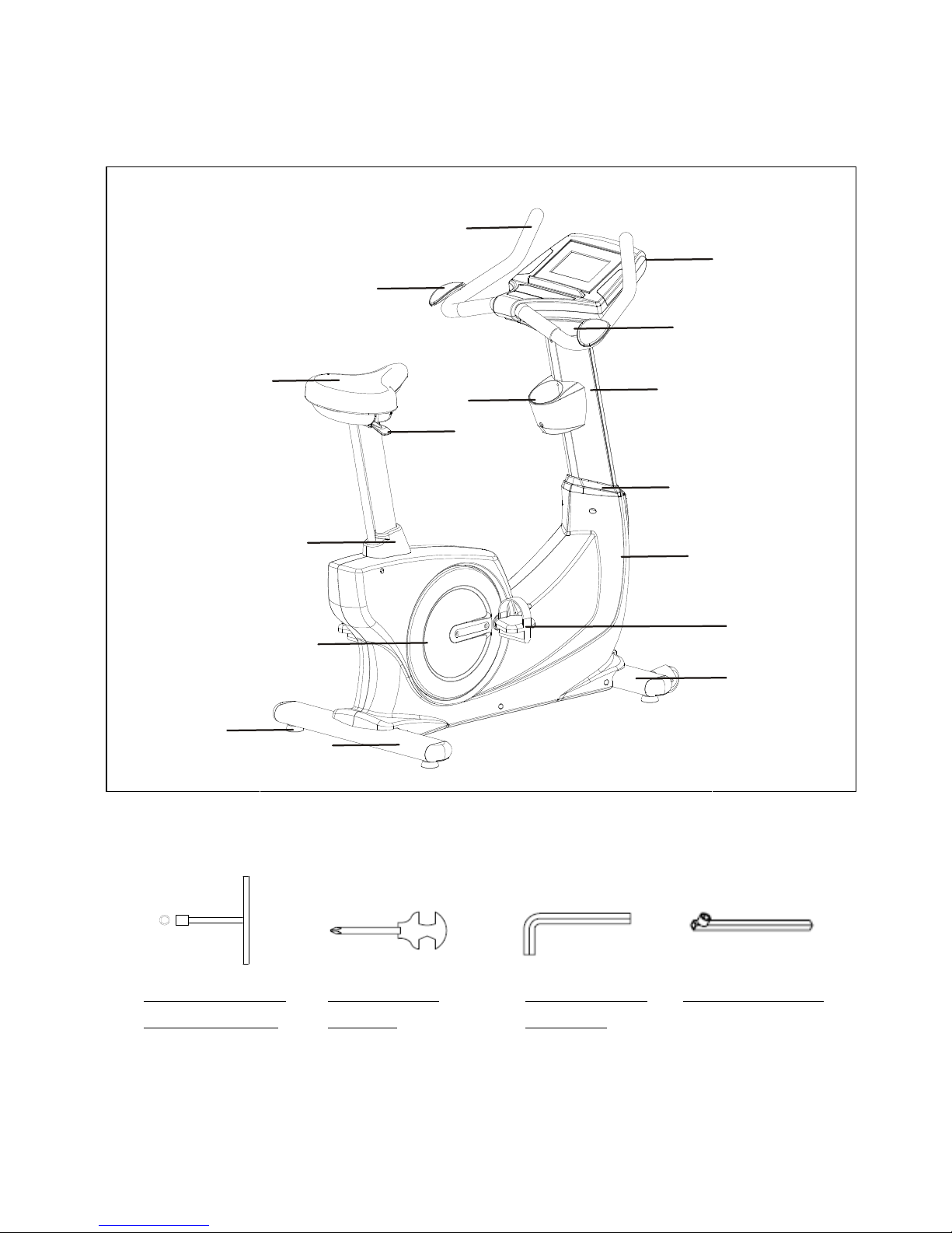
TOOLS NEEDED FOR THE ASSEMBLIES (INCLUDED)
T-HANDLE SOCKET
WRENCH (17MM)
ALLEN WRENCH
(M5 & M6)
SOCKET WRENCH
COMBINATION
WRENCH
Handlebar
Arm Rest Pad
Console
Seat Adjustment
Handle
Console Bracket
Upright Post
Seat Cap
Crank Cover
Upright Sleeve
Main Frame
Right Pedal
Front Stabilizer
Rear Stabilizer
Floor Leveler
Water Bottle
Holder
Seat

5
HARDWARE
This chart below is provided to help identify the hardware used in the assembly process.
Use the circles below to confirm the diameter of each Washer, Bolt and Screw.
Use the small ruler to check the length of the bolt and screw.
NOTICE: The length of the bolt or screw DOES NOT the head to the bolt
or screw.
After unpacking the unit, open the hardware bag and make sure that you have all the following items. Some
hardware may be already attached to the part.
Part Number
Description
Qty
78
Lock Washer (M8)
4
73
Washer (8x38x2.0t)
4
83
Screw, Round Head (M5xp0.8x15mm)
12
84
Screw, Round Head (M5xp0.8x50mm)
2
88
Bolt, Button Head (M6xp1.0x12mm)
2
97
Bolt, Hex Head (M8xp1.25x65mm)
4
99
Bolt, Hex Head (M10xp1.5x50mm)
2
6
ASSEMBLE INSTRUCTIONS
Place all parts from the box in a cleared area and position them on the floor in front of you.
Remove all packing materials from your area and place them back into the box. Do not dispose of
the packing materials until assembly is completed. Read each step carefully before beginning.
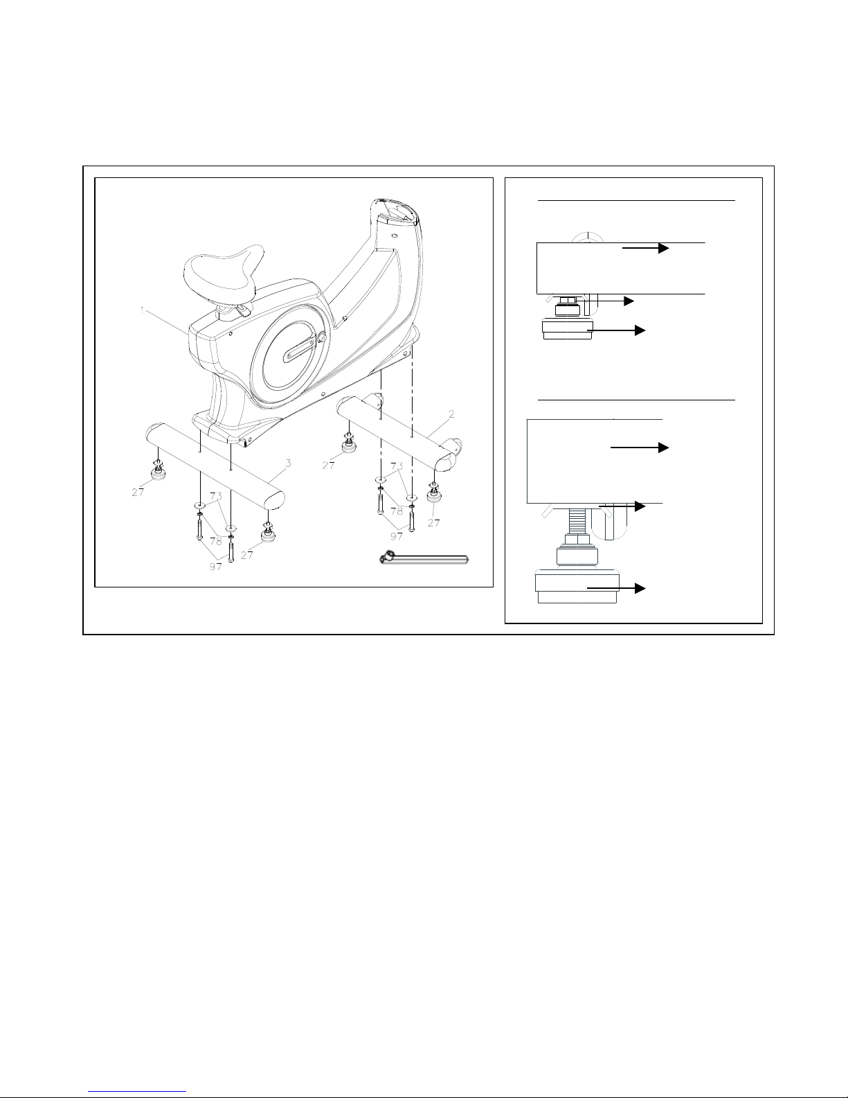
STEP 1
Attach the Floor Leveler (27) to the Front Stabilizer (2)
STEP 2
Attach the Front Stabilizer (2) and the Rear Stabilizer (3) to the Main Frame Assembly
(1), secure it using 4 Washers (8x38x2.0t)(73), 4 Lock Washers (M8)(78) and 4 Hex
Bolts (M8xp1.25x65mm)(97). Tighten it securely with the socket wrench (as shown).
Adjust the Floor Leveler if the Bike is NOT leveled to the floor. Make sure the Metal
Plates are fully tightened.
Detailed Lever- drawing 1
Detailed Lever- drawing 2
Metal Plate
Stabilizer
Floor Leveler
(27)
Stabilizer
Adjustment Plate
Floor Leveler
(27)
7
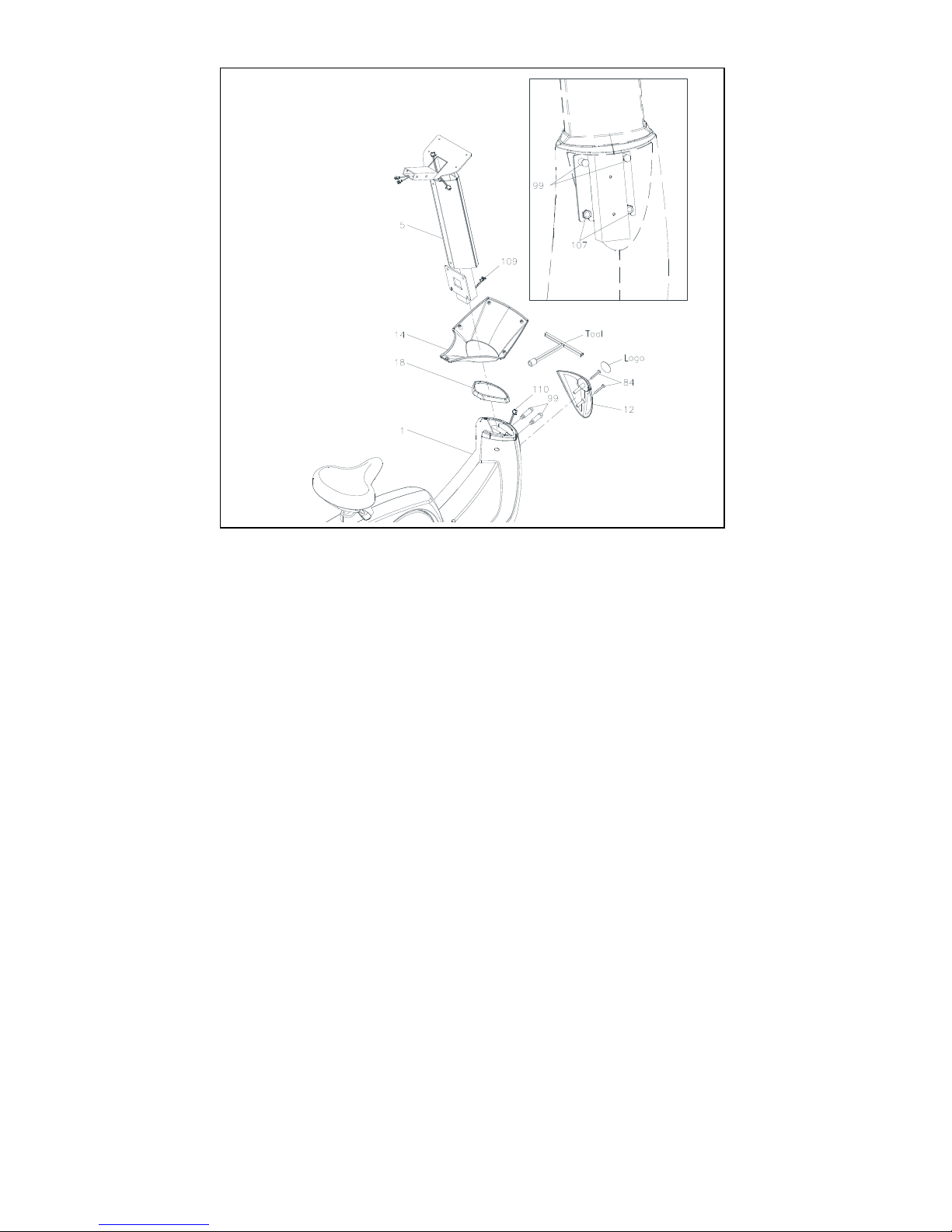
STEP 3
Slide the Console Bracket (14) and the Upright Sleeve (18) onto the Upright Post (5.)
Make sure the Metal Plate that holds the Display Console is facing forward (as shown).
Be careful not to pinch the wire (Middle Connection Wire (109)).
STEP 4
Insert 2 Nylon Lock Nuts (M10) (107) into the front of the Main Frame (1) (as
shown)
Install the Upright Post (5) to the Main Frame (1) using 2Hex Bolts
(M10xp1.5x50mm) (99). Secure it with the T-HANDLE SOCKET WRENCH (17MM).
STEP 5
Connect the Middle Connection Wire (109) to the Lower Connection Wire (110.)
Attach the Front Decorative Cover (12) onto the front of the Main Frame (1), secure
it with 2 Screw, Round Head (M5xp0.8x50mm)(84.)
Paste a Logo Sticker on the surface of the Front Decorative Cover (12). Lower the
Sleeve (18) to cover the gap on the Main Frame Housing.

8
STEP 6
Connect the Lower Pulse Sensor Wire (113) and the Middle Pulse Sensor Wire
(112B).
Install the Handlebar (6) to the Upright Post (5), secure it using 4 Lock Washers
(M8)(78) and 4 Bolts, Button Head (M8xp1.25x16mm)(90). Tighten it securely with
wrench.
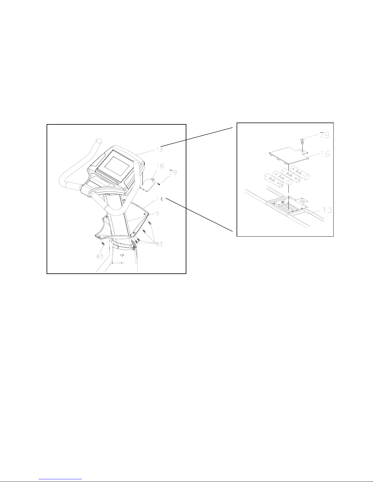
STEP 7
Loosen the Screw (M3x10mm)(79) then open the Battery cover. Install 4 AA
rechargeable batteries (included) (Please only use the Nickel-Metal Hybrid/NI-MH
rechargeable battery).
STEP 8
Re-Attach the Battery Cover (16) back of the Display Console (13) and the Screw
(M3x10mm)(79).
STEP 9
Connect the Middle Pulse Sensor Wire (112A) to the Middle Pulse Sensor Wire (112)
then connect the Middle Connection Wire (109A) to the Middle Connection Wire
(109).
STEP 10
Install the Display Console (13) to the Metal Bracket on the Upright Post (5), secure it
with 4 Screws, Round Head (M5xp0.8x15mm)(83) using a Philip screw driver.
STEP 11
Attach the Console Lower Case (15) to the Display Console (13) and secure it with 1
Screw, Round Head (M5xp0.8x15mm)(83) using a Philip screwdriver.

9
STEP 12
Install the Display Console Bracket (14) onto the Console (13) and secure it with 4
Screws, Round Head (M5xp0.8x15mm)(83). Tighten it securely with wrench.
STEP 13
Install the Arm Rest Pads (28) onto the Handlebar (6), secure it with 2 Bolts, Button
Head (M6xp1.0x12mm)(88). Tighten it securely with wrench.
STEP 14
Install the Water Bottle Holder (17) onto the Upright Post (5) using 2 Screws, Round
Head (M5xp0.8x15mm)(83), secure it with a Philip Screw Driver.
STEP 15
Install the Right Foot Pedal (11) onto the Right Crank Cover (9), Securely tighten it with
wrench by turning it Clockwise. Install the Left Foot Pedal onto the Left Crank Cover by
turning it Counter-Clockwise.
10
OPERATIONS INSTRUCTIONS
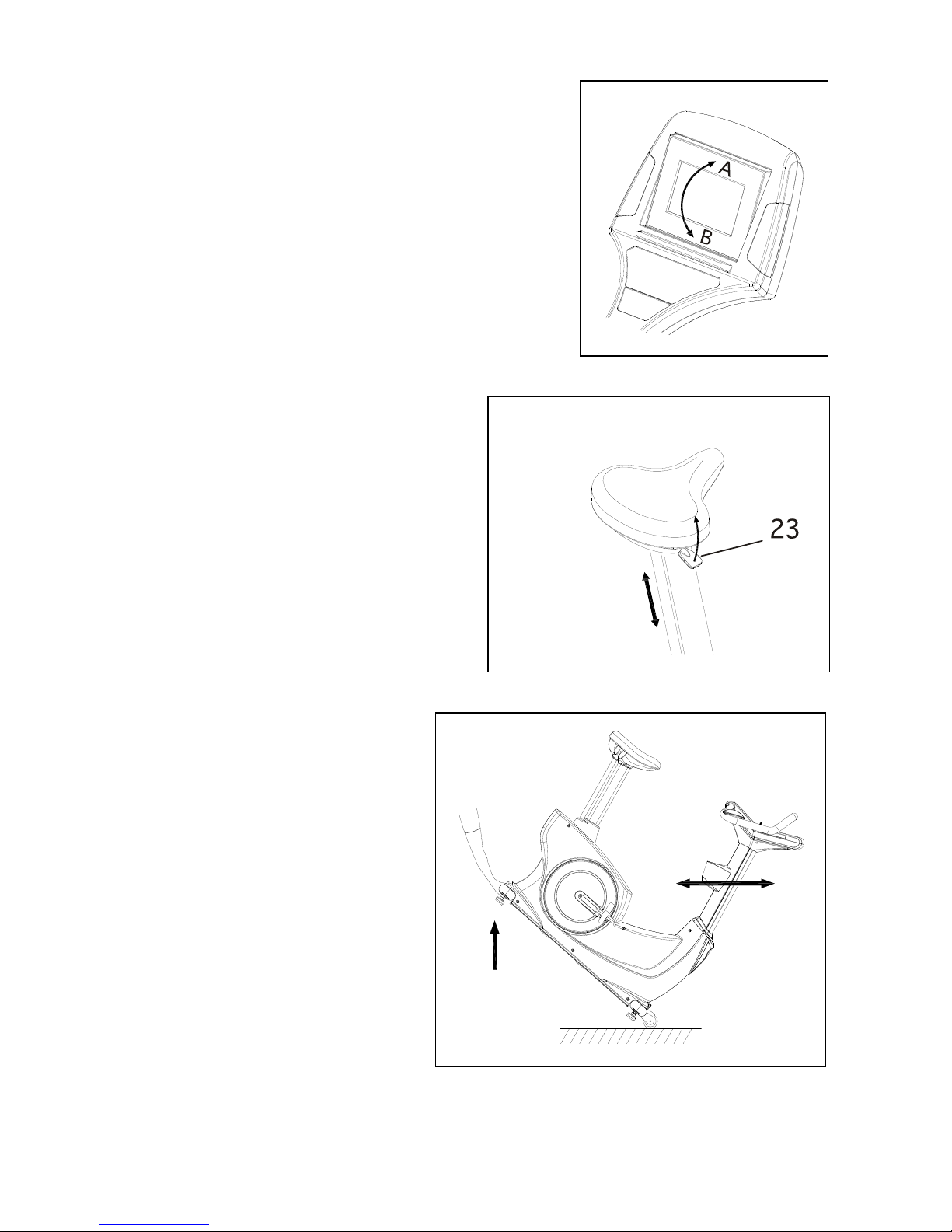
CONSOLE ANGLE ADJUSTMENT
The Display Console angle may be adjusted by pushing
the
A or B on the Display Console
SEAT HEIGHT ADJUSTMENTS
The Seat Height may be adjusted by pull the
Adjustment Handle (23) upward to adjust
the seat height.
Release the Adjustment Handle (23) after
it’s done.
TRANSPORT YOUR UPRIGHT BIKE
SAFELY
Lift and Hold the Rear Stabilizer (3) up
with two hands and move your upright
bike to the desired place carefully.
Make sure the floor is level while
transporting the upright bike.
11
HOW TO INSTALL AND REPLACE BATTERIES:
Loosen the Screw (83) at the bottom on the Console Bracket (14).
Loosen the Screw (M3x10mm)(79) that locks the battery cover.
Install (or Replace) only the Nickel-Metal Hybrid/NI-MH rechargeable batteries.

12
PARTS LIST
NO.
Description
Q'TY
1
Main Frame
1
2
Front Stabilizer
1
3
Rear Stabilizer
1
4
Seat Post
1
5
Upright Post
1
6
Handlebar
1
7
Left Cover
1
8
Right Cover
1
9
Crank Cover
2
10
Left Pedal
1
11
Right Pedal
1
12
Front Decorating Upright Cover
1
13
Console
1
14
Console Bracket
1
15
Console Lower Case
1
16
Battery Door
1
17
Accessory Tray
1
18
Upright Sleeve
1
19
Seat
1
20
Seat Lower Case
1
21
Seat post Sleeve
1
22
Seat Cap
1
23
Adjustment Bar
1
24
Slider
1
25
End Cap (50x100mm)
4
26
Moving Wheel
2
27
Leveler (ψ50)
4
28
Hand Wrist Pad
2
29
Foam Grip (550mm)
2
30
Foam Grip (40mm)
2
31
Pulse Sensor Top Housing
2
32
Pulse Sensor Bottom Housing
2
33
Pulse Sensor Plate
4
34
Generator
1
35
Pulley (120mm)
1
36
Belt (762mm J8)
1

13
NO.
Description
Q'TY
36
Belt (762mm J8)
1
37
Pulley (235mm)
1
38
Magnet
1
39
Belt (1092mm J8)
1
40
Front Aluminum Upright Cover
1
41
Rear Aluminum Upright Cover
1
42
Air Pressure Bar
1
43
Seat Adjustment Lever
1
44
Fixed Stand
1
45
Spacer
1
46
Cable
1
47
Cable Spring
1
48
Roller Axle
1
49
Stand Spring
1
50
Spacer Stand
1
51
Arc Washer
1
52
Resistor
1
53
Controller
1
54
Right Mounting Plate
1
55
Left Mounting Plate
1
56
Idler Spring
1
57
Washer (ψ10.6×ψ60×2.0t)
1
58
Idler Arm
1
59
Axle Connection Cap
1
60
Bearing 6004ZZ
8
61
Idler Wheel Spacer
1
62
One Way Pulley (51)
1
63
One Way Bearing (2520)
1
64
Axle
1
65
Right Crank
1
66
Left Crank
1
67
Crank Shaft
1
68
Eye Bolt
4
69
Tension Bracket
2
70
Square Key (6×6×15mm)
1
71
E Ring
1
72
Crescent Ring
4

14
NO.
Description
Q'TY
73
Washer (8×38×2.0t)
4
74
Washer (10×23×2.0t)
2
75
Washer (17×25×1.0t)
1
76
Washer (18.3×25×1.0t)
1
77
Washer (20×1.0t)
2
78
Lock Washer (M8)
13
79
Screw (M3×10mm)
1
80
Screw (M4×20mm)
4
81
Screw (M5×18mm)
19
82
Screw, Round Head (M3×35mm)
4
83
Screw, Round Head (M5×p0.8×15mm)
12
84
Screw, Round Head (M5×p0.8×50mm)
2
85
Screw, Round Head (M5×p0.8×75mm)
2
86
Bolt, Round Head (M6×p1.0×10mm)
4
87
Bolt, Round Head (M6×p1.0×15mm)
4
88
Bolt, Button Head (M6×p1.0×12mm)
4
89
Bolt, Button Head (M8x35mm)
2
90
Bolt, Button Head (M8×p1.25×16mm)
5
91
Bolt, Button Head (M10×p1.5×45mm)
1
92
Screw, Flat Head (M8×p1.25×12mm)
5
93
Bolt, Socket Head (M8×p1.25×55mm)
2
94
Bolt, Socket Head (M10×p1.5×30mm)
1
95
Bolt, Hex Head (M8×p1.25×15mm)
4
96
Bolt, Hex Head (M8×p1.25×10mm)
1
97
Bolt, Hex Head (M8×p1.25×65mm)
4
98
Bolt, Hex Head (M8×p1.25×80mm)
4
99
Bolt, Hex Head (M10×p1.5×50mm)
2
100
Nut (M3)
4
101
Flange Nut (M5)
2
102
Nut (M6)
3
103
Nut (M8)
3
104
Nylon lock Nut (M6)
2
105
Nylon lock Nut (M8x6.2t)
8
106
Nylon lock Nut (M8)
6
107
Nylon lock Nut (M10)
4

15
NO.
Description
Q'TY
108
Generator Wire
2
109
Middle Connection Wire
1
110
Lower Connection Wire
1
111
Sensor Wire
1
112
Middle Pulse Sensor Wire
1
113
Lower Pulse Sensor Wire
2
114
Washer (8×23×2.0t)
2
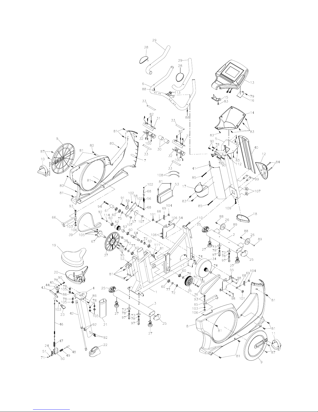
EXPLODED DRAWING

17

18
Table of contents
Popular Exercise Bike manuals by other brands


Sunny Health & Fitness
Sunny Health & Fitness SF-B121021 user manual

Monark
Monark 827E instruction manual

Stamina
Stamina 1310 owner's manual

American Fitness
American Fitness SPR-BK1072A owner's manual
 Service manual")
Cateye
Cateye CS-1000 (CYCLO SIMULATOR) Service manual

BH FITNESS
BH FITNESS H9158H Instructions for assembly and use