TKR Group 83 30 5 A62 332 User manual
R1-22.07-V1
83 30 5 A62 332
83 30 5 A62 333
83 30 5 A62 334
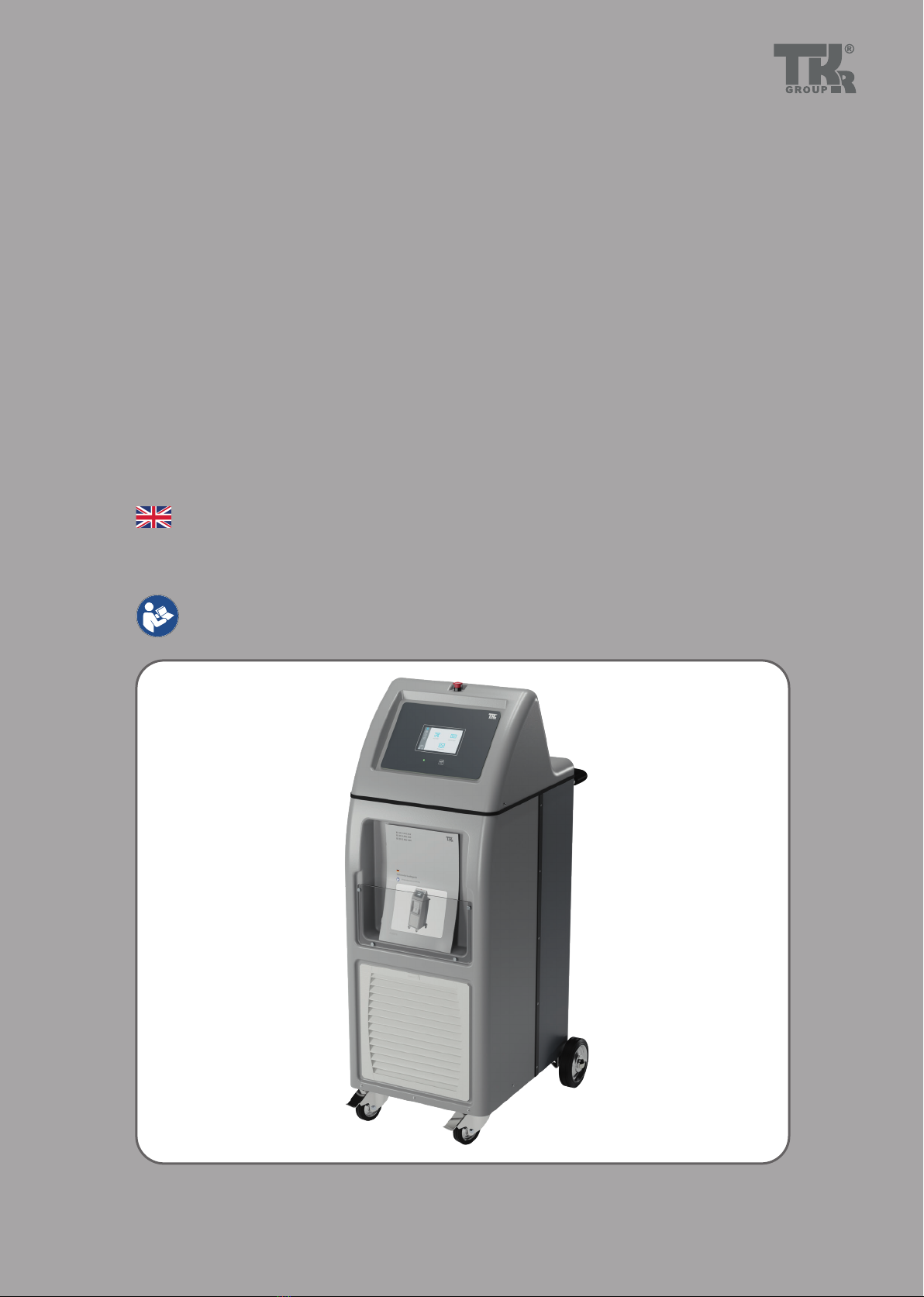
Cell module charger
Translation of the original owner's manual

2
?
Owners manual, digital
Europe
Worldwide
www.tkr-service.comOwners Manual USB-Stick
Owners manual, digital
Europe
Worldwide

3
This owner's manual is protected by copyright. Any use beyond the restrictions imposed by copyright legislation undertaken without the permission of the manufacturer is
illegal and punishable by law. This also applies to the extraction of individual illustrations and use of texts as excerpts.
1. Safety
1.1 General instructions 4
1.2 Explanation of symbols 5
1.3 Labelling 5
1.4 Scope of supply 6
1.5 Safety instructions 7
2. Technical data
2.1 Technical Specications 8
2.2 Technical data 9
2.3 Device components 10
2.4 Accessory list 12
3. Installation
3.1 Intended use 13
3.2 Working with the tool - basic principles 13
3.3 Commissioning and safe handling 14
3.4 Country-specic connection conguration 15
3.5 Country-specic connection conguration: :
3-phase system 17
3.6 Country-specic connection conguration:
2-phase system 18
3.7 Country-specic connection conguration:
Single-phase system 19
3.8 Country-specic connection conguration:
Closing 20
3.9 AC mains input connection 21
3.10 Connecting the cell module 23
4. Use
4.1 Startup 24
4.2 Overview of menu symbols 25
4.3 Starting the charging/discharging process 26
4.4 Cell module diagnostics 29
4.5 System menu 30
4.6 System update 31
4.7 Superuser functions 32
4.8 Changing the module parameters 33
4.9 Info menu 34
4.10 Putting out of operation and storage 35
5. Maintenance
5.1 Troubleshooting 36
5.2 Maintenance 36
5.3 Spare parts 36
6. Service
6.1 Disposal 37
6.2 Warranty & Service 37
6.3 EU Declaration of Conformity 38
UK Declaration of Conformity 39

4
6.3
1.1 General instructions
State-of-the-art
This tool is state-of-the-art technology. To ensure that the
equipment operates safely, it must be operated in a proper and
safety-conscious manner.
Technical changes
In the interests of quality assurance, we reserve the unrestricted
right to carry out technical changes as a result of further techno-
logical developments and product improvements without prior
notication.
Reading the owner's manual
Before using the tool, make sure you read the own-
er's manual carefully and understand it. This manual
must always be available where the product is used.
Handling
All the actions necessary to ensure correct operation are de-
scribed in the owner's manual. Any working methods other than
those approved by the manufacturer are prohibited.
Faults
If faults occur, the operator may only eliminate those faults
through their own actions where the corresponding remedy is
described.
Warranty
The manufacturer accepts no liability for damage or injury
caused by improper repair or the use of third-party replacement
parts.
No warranty will be provided for damage caused to the device
due to the tool being used incorrectly.
Environment
Make sure that the tool is set up in a work area which is free from
sources of heat (max. 50°C / 122 °F), corrosive liquids, greases or
oils.
Declaration of Conformity
The tool has been manufactured in accordance with
international guidelines. The relevant declaration of
conformity (CE, UKCA, CB) is included with this own-
er’s manual.
Risk of damage to the tool
The tool must only be used as described in the in-
struction manual. It is expressly forbidden to misuse
the tool or to use it for any other purpose. Please
make sure that you and your sta handle the tool
correctly.
Risk of injury
In addition to the owner's manual and the binding
provisions of the accident prevention regulations
which apply in the country and at the place of use,
you must also comply with the general (accepted)
rules for safe and professional working.
Electrician
Only trained and instructed personnel are authorized to carry
out the repair / maintenance work on the vehicles and vehicle
components concerned.
5
Zellmodul-Ladegerät
83 30 2 472 435 61
Serien-Nr.: 00072
KW: 08/22
Input: 100-240 V~ max. 42A /
100-415 V 3~ 3x 16A / 50-60 Hz
Output: 5-250 V
⎓/
1-40 A / max. 6 kW
TKR Cable Systems GmbH
Am Waldesrand 9-11, D-58285 Gevelsberg
B
A
K
H
L
J
I
G
C
D
E
F
1.3.1
1.3.2
TÜVRheinland
CUS
1.2 Explanation of symbols
Follow the manual
Follow the general
instructions
Warning!
General source of danger
High voltage!
Danger to life!
Caution!
Risk of explosion
Caution!
Electrostatically sensitive
components
Protective insulation
Direct current
(DC Direct Current)
Please note the following...
Arrow to clarify
compression
For more information,
see chapter …
Arrow showing direction
cTUVus Certication
CE symbol
UK Conformity Assessment
Product certicate
https://www.tkrgroup.com/
module-charger-cert.htm
Some chapters in this instruction manual use internationally recognised warning symbols, warning notes and general in-
struction symbols.
The individual symbols are explained below. Follow all the instructions and safety rules.
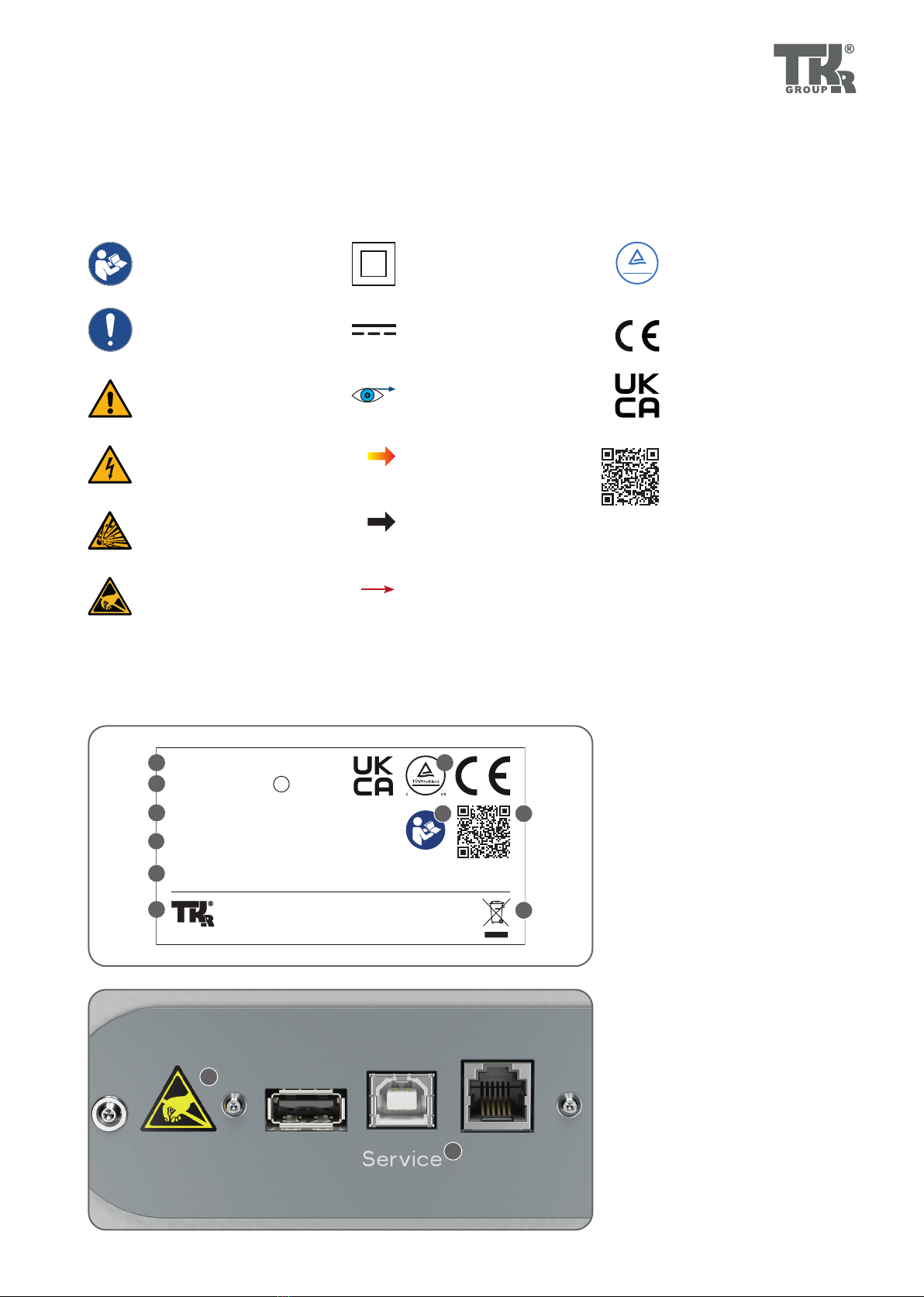
1.3 Labelling
A Manufacturer's label
B Article number
C
Serial number /
Date of manufacture
D Input specification
E Output specification
F Company address
G UKCA mark /
cTUVus Certification /
CE mark
H Follow owner's manual
I QR code
J Disposal
K Warning symbol for
electrostatically sensitive
components
L Service connection

6
A
A
A
B
B
B
C
C
C
D
D
D
E
E
E
1.4 Scope of supply
A Cell module charger
(83 30 2 472 435)
B Owner’s manual
C 40 A module charging
cable (83 30 5 A47 B88)
D Cell contacting system
(83 30 5 A47 BC6)
E Mains power cable CEE
(83 30 2 472 436)
A Cell module charger
(83 30 2 472 435)
B Owner’s manual
C 40 A module charging
cable (83 30 5 A47 B88)
D Cell contacting system
(83 30 5 A47 BC6)
E Mains power cable NEMA
(83 30 2 472 437)
A Cell module charger
(83 30 2 472 435)
B Owner’s manual
C 40 A module charging
cable (83 30 5 A47 B88)
D Cell contacting system
(83 30 5 A47 BC6)
E Mains power cable
(83 30 5 A3B 089)
Set 83 30 5 A62 332
Set 83 30 5 A62 333
Set 83 30 5 A62 334
7
1.5 Safety instructions
CAUTION
If used with the wrong accessories, this may cause
material damage and bodily injury.
Not using original tools and original accessories will
result in a high risk to safety.Only original accessories
may be used.
The manufacturer cannot accept any liability for con-
versions or modifications to the tool.
CAUTION
Trip hazard
Laying supply cables carelessly can lead to acci-
dents through tripping, twisting of the ankle or falls
or may even damage the cables.
Lay all supply cables so that they cannot be dam-
aged and nobody can trip over them.
CAUTION
Risk of material damage and bodily injury
You must read and understand the safety instructions
before carrying out the repair.
Not reading the instructions may result in serious
bodily injury.
CAUTION
Risk of material damage and bodily injury
Only technical personnel who have received instruc-
tion are authorized to operate this tool. The tool must
not be lent to untrained persons. Ensure that the tool
is only operated by trained personnel who are in-
structed in its use!
CAUTION
Risk of damage to the tool
Not handling the tool properly can lead to damage to
the tool. Never allow the tool to topple over.
CAUTION
Risk of personal injury
In order to avoid receiving an electric shock, make
sure that this tool is not connected to a power
source before carrying out any configuration, clean-
ing or maintenance work on it. Just switching off the
tool or pressing the disconnecting button does not
reduce the risk.
CAUTION
Risk of explosion!
This tool has internal arcing or sparking compo-
nents which must not come into contact with flam-
mable vapours.
The tool must never be used in potentially explosive
areas.
CAUTION!
Electrostatically sensitive components
The device contains electronic components which
are sensitive to electrostatic discharge (ESD). These
components are at risk of being damaged by contact
with electrostatically charged persons or objects. In
the worst case, they will be destroyed or will fail.
Prevent electrostatic discharge by grounding the per-
son touching the tool beforehand.
Ensure that the owner's manual is made available
to the operating personnel.
Each operator must carefully read and understand
this owner's manual before using the tool for the first
time. This owner's manual must always be available
where the product is used.
Follow the applicable national regulations for the
prevention of accidents.
In addition to the owner's manual and the binding
provisions of the accident prevention regulations
which apply in the country of use, you must also com-
ply with the general, accepted rules for safe and pro-
fessional working.

8
If any abnormality is identied, the tool must not be used.
Please contact Service ( 6.2).
The tool is strictly approved solely for the purpos-
es for which the manufacturer has designed it.
The tool must only be used for the activities described
in this owner's manual. Never use the tool for any pur-
pose except that for which it is designed. Safety is no
longer guaranteed if the tool is used incorrectly.
Make sure that the tool is not operating unsuper-
vised over long periods of time.
An administrator account may be necessary to in-
stall the drivers.
The tool may only be used in ambient tempera-
tures from 0°C / 32 °F min. to 50 °C / 122 °F max.
Voltage supply
see table
Climate conditions
see table
Electromagnetic compatibility (EMC)
In compliance with EN61326-1:2013 (IEC61326-1:2012)
Cell module charger GEN5
Type of device Cell module charger
Ambient temperature (operation) 0 °C to +50 °C, +32 °F to +122 °F
Ambient temperature (storage) -20 °C to +60 °C, -4 °F to +140 °F
Maximum altitude for use 2000 m
Ambient humidity Up to 85% (non-condensing)
Pollution category 2
Safety IEC 61010-1
Protection class IP 20
Overvoltage category II
Device dimensions 1159x530x642 mm (HxWxD)
Input current 3x 16 A
Total weight 62 kg
2.1 Technical Specifications

9
1053
100,5
417
530
527
585,5
1159
642
2.2 Technical data
AC mains input
Mains voltage star 240–415 V (+/-10%), 50-60 Hz
Mains voltage delta 100–240 V (+/-10%), 50-60 Hz
Mains voltage single-phase, 2-phase 100–240 V (+/-10%), 50-60 Hz
Mains fuse 3x 6,3x32 mm 16A T, 1x 5x20 mm 1A T
Leakage current < 3.5 mA
DC charging output
Max. voltage 250 V
Max current 40 A at U ≤150 V, I= 6000 W / U at U > 150 V
Max power 6 kW
Range of adjustment 5–250 V
Adjustment range accuracy 1–40 A
Eciency accuracy up to 93%
Fuse 1x 10.3x38 mm 50A 1000V

10
F
A
B
CD
E
G
2.3.1
2.3 Device components

11
H
I
J
K
LM
N
O
P
Q
R
2.3.2 2.3.4
2.3.4 2.3.5
USB connection
Service connection
RJ12 connection
Locking lever
Protective cover
Service access
Cable loop
AC mains input
2.3.1-2.3.5 Cell module charger
Emergency stop switch
Touch display
Signal LED
Function key
Front compartment
Ventilation grill
Casters with locking brakes
Handle
DC charging connection
CCS connection
A
B
C
O
Q
E
F
D
P
R
G
H
I
J
K
L
M
N
12
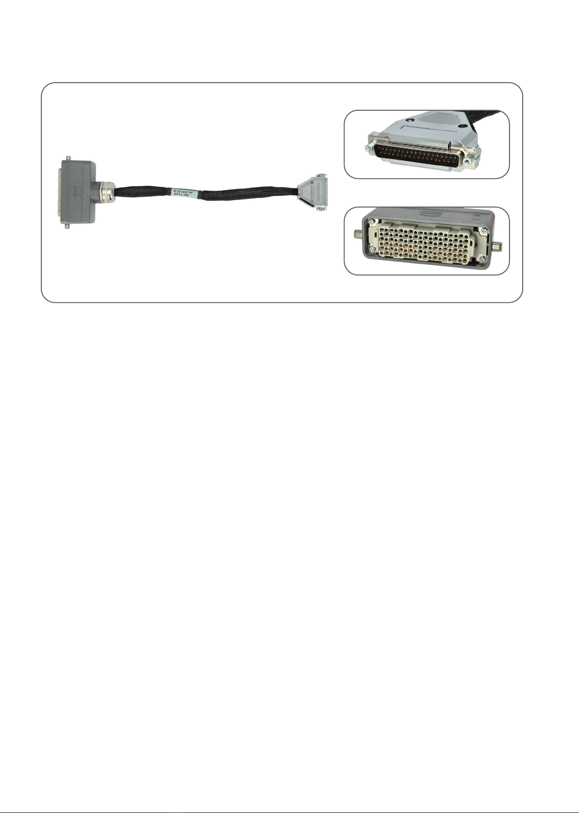
GEN5 module charging adaptor (83 30 5 A36 706)
for adapting GEN3 / GEN4 charging cables
2.4 Accessory list

13
3.1 Intended use
3.2 Working with the tool - basic principles
The cell module charger is a diagnostic system for the individ-
ual cell modules of a HV battery. It is used for the hazard-free,
touch-protected charging and discharging of cell modules.
Its use is described in the corresponding repair instructions.
Follow the work instructions from the guided troubleshooting
of the brand.
Risk of injury
It is vitally important that you make sure that you
are handling the tool correctly.
It is expressly forbidden to misuse the tool or to
use it for any other purpose.
The tool must only be used as described in the
instruction manual.
Warranty
The manufacturer accepts no liability for damage
or injury caused by improper repair or the use of
third-party replacement parts.
No warranty will be provided for damage caused to
the device due to the tool being used incorrectly.
The tool monitors all the parameter of the cell module which are
required for safe use so that the adjustment process is aborted
automatically when the limits are exceeded.
Environment
The tool may only be used in a work area
which is free of sources of heat (max. 50°C /
122 °F), corrosive liquids, greases and oils.
Leave to acclimatise before starting.
Avoid the formation of condensation.
Make sure that the area is well ventilated to avoid
the build-up of explosive vapours.
Declaration of Conformity
The tool has been manufactured and tested in
accordance with the European directives. The Dec-
laration of Conformity is included with this owner's
manual.
6.3

14
3.3 Commissioning and safe handling
CAUTION
Risk of injury
Lay all supply cables so that they cannot be damaged
and nobody can trip over them.
CAUTION
Risk of injury
You may only supply the tool with electrical power
after you have carried out the steps in chapters 3.4
and 3.5.
CAUTION
Risk of injury
The tool may only be operated with the parking
brake [G] applied to prevent it from rolling away
during operation.
Park the tool on a level surface before use.
Release the locking brakes [G] before repositioning
the tool.
In order to avoid contamination or damage to the
tool components, do not place anything on the tool.
Before using the tool, make sure that the air supply
and exhaust air systems [F] are not blocked so that it
does not overheat.
As soon as the system overheats, the process is
aborted.
Only set up the tool in well ventilated areas.
Protect the tool from moisture, humidity and con-
densation. Avoid using liquids of any kind in the
proximity of the tool. These can get into the tool.
Check the tool for any damage every time
before
using it.
Carry out a visual inspection of the supply cables
every time before using it.
Make sure that the tool has sucient time to
acclimatise before putting it into operation.
The tool may only be used inside buildings and
must be protected from weather outside (indoor
use only).
Before putting the tool into operation for the rst time, carry out the
country-specic connection congurations ( 3.4).

15
7000 W
6000 W
5000 W
4000 W
3000 W
2000 W
1000 W
0 W
100 V 150 V 200 V 250 V 300 V 350 V 400 V
P3 Υ
P3 ∆
P1-2
3.4 Country-specific connection configuration
CAUTION
Danger to life!
The connection conguration for the tool must only
be carried out by a trained electrician.
CAUTION
Danger to life
The tool must be fully de-energized before and
during the connection conguration. Follow the acci-
dent prevention and safety regulations for electrical
devices!
Before putting the tool into operation for
the rst time, it must be congured for your
mains connection. Carry out the country-
specic connection conguration for it accord-
ingly.
The country-specic connection conguration
must only be carried out by an electrician. If the
mains connection is changed, the connection
conguration must be adjusted to the change by
an electrician.
Make sure that your connection conguration
agrees with the mains connection which you are
using.
The tool is normally supplied with the connection
in star conguration. Set 83 30 5 A62 334 is deliv-
ered with open bridges.
The maximum power can be achieved at operat-
ing voltages >150 V.
3.4.1 Derating dependent on the operating voltage

16
3.4.2
O
3.4.3
P
3.4.4
3.4.2 Removing the protective cover
Loosen the three screws on the protective cover [O]. Remove the
protective cover and put it aside together with the screws.
3.4.3 Opening the service access
Loosen the three screws on the plate for the service access [P].
Open the service access to carry out the country-specic con-
nection conguration.
The mains cable box is not included in set 83 30
5 A62 332.
3.4.4 Opening the mains cable box
Loosen the screws on the mains cable box of the required
mains cable and put it aside. Now remove the cover. Make the
jumpering of the cables according to the specications of the
country-specic connection congurations.
Circuit diagrams
3-phase system: 3.5.1, 3.5.2
2-phase system: 3.6.1
1-phase system: 3.7.1

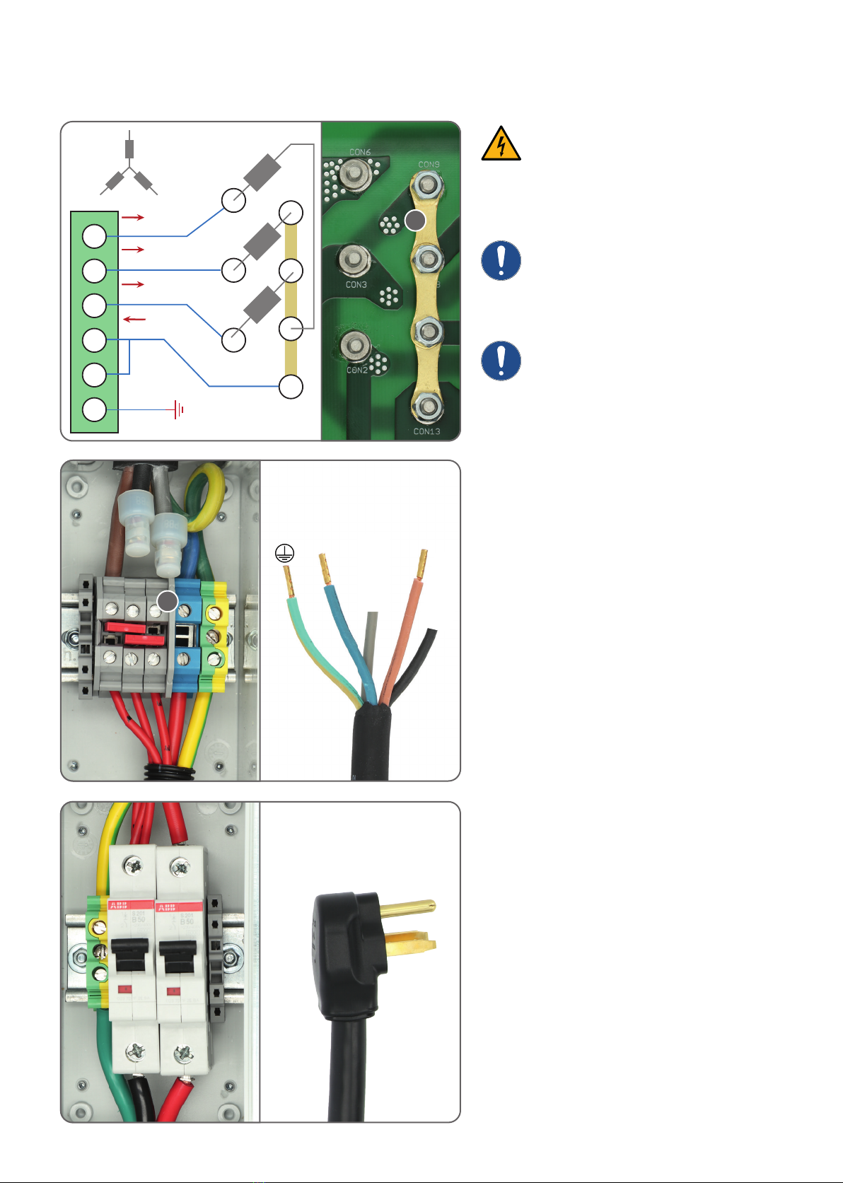
17
3.5.33.5.3
L3 L1 L2
N
1L1
L2
L3
N
PE
6
3.5.13.5.1
S
S
S
1L1
L2
L3
N
PE
6
3.5.23.5.2
S
3.5.4 83 30 2 472 436
83 30 5 A3B 089
3.5 Country-specific connection configuration:
3-phase system
3.5 - 3.7 Circuit diagrams
The tool normally operates with star connection. The tool must
be congured dierently depending on the country specica-
tion and power supply system.
CAUTION
Risk of damage to the tool
In a 3-phase system at mains voltages of more than
240 V, it is essential to use the star connection in or-
der to avoid a malfunction within the tool.
CAUTION
In a 3-phase system, do not set jumpers [T] in the
mains cable box, otherwise a short circuit will occur
(3.5.1).
Please ensure standard-compliant fuse protec-
tion according to the rules of technology.
3.5.1 Delta connection
The tool must be operated in delta conguration using a 3-phase
system with the 3 outer conductors L1, L2, L3 and a neutral con-
ductor N and with an outer conductor voltage 100–240 V (L1–L2,
L2–L3, L3–L1).
The jumpers [S] must be installed according to the picture. The
fastening nuts must be tightened to a torque of 1.2 Nm.
3.5.2 Star connection
The tool must be operated on a 3-phase system in star con-
guration with the 3 outer conductors L1, L2, L3 and a neutral
conductor N and with an outer conductor voltage 240–415 V
(L1–L2, L2–L3, L3–L1).
The jumpers [S] must be installed according to the picture. The
fastening nuts must be tightened to a torque of 1.2 Nm.
3.5.3 - 3.5.4 Suitable mains connection cables
83 30 5 A3B 089
83 30 2 472 436
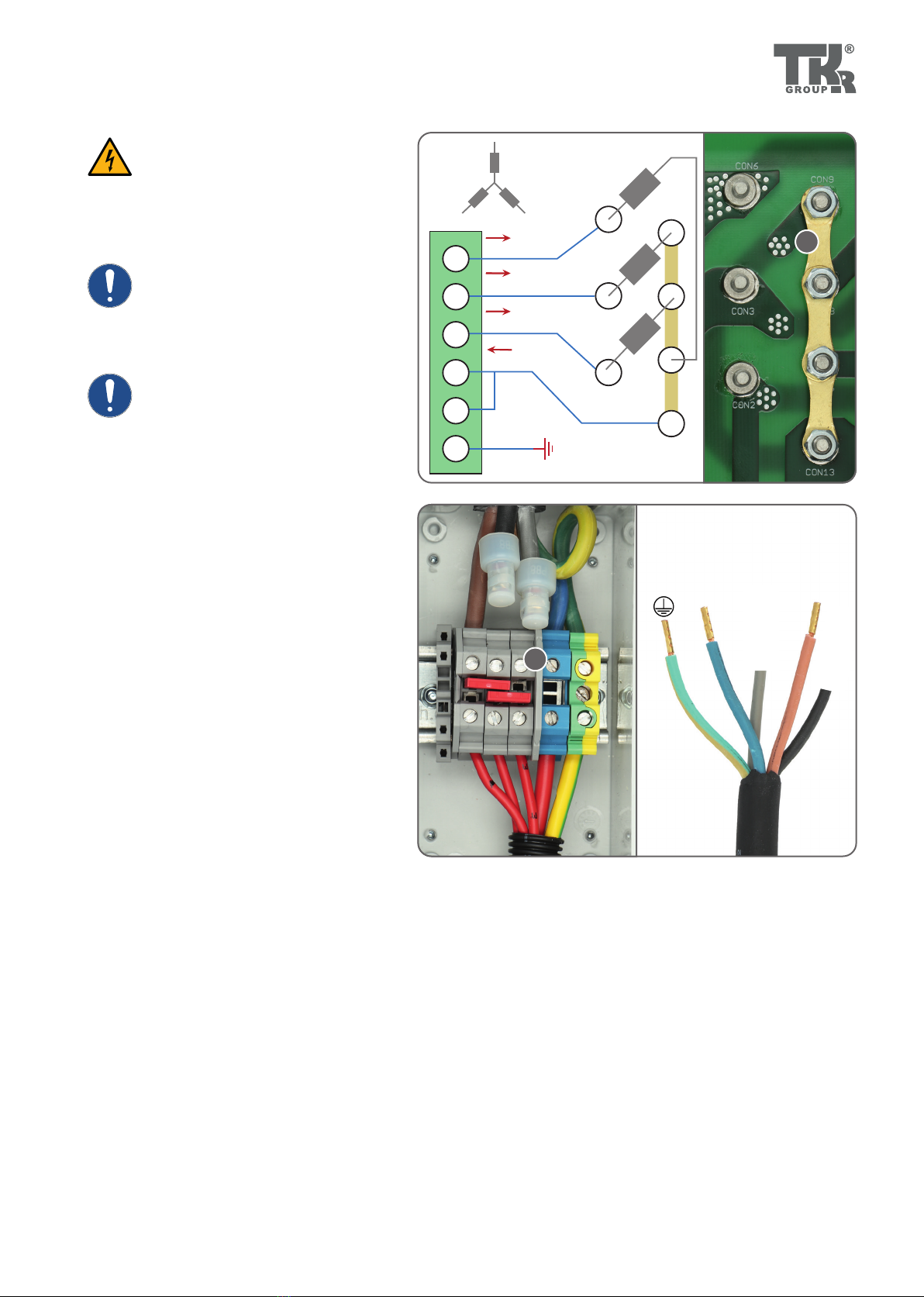
18
1L1 max. 13.5 A
L1 max. 13.5 A
L1 max. 13.5 A
L2 max. 40.5 A
PE
6
3.6.13.6.1
T
3.6.23.6.2 83 30 5 A3B 089
L1
L2
S
3.6.33.6.3 83 30 5 A3B 089
3.6 Country-specific connection configuration:
2-phase system
CAUTION
It is essential that the black and grey
wires in the mains cable box are dis-
connected, otherwise the shortened
ends of the wires will be live.
The maximum rated current is 40.5 A.
Make sure that the conductor cross
section is suciently large for the
mains conductor.
Please ensure standard-compliant
fuse protection according to the rules
of technology.
3.6.1 2-phase connection
In a 2-phase system with the outer conductors L1, L2,
neutral conductor N and an outer conductor voltage
of 100–240 V (L1–L2), the tool is to be operated in
2-phase connection.
The jumpers [S] must be installed according to the
picture. The fastening nuts must be tightened to a
torque of 1.2 Nm.
3.6.2 Circuit Mains Cable Box
If a 2-phase connection is used, the cables must be
bridged with the jumpers [T] according to gure
3.6.2. Remove the grey and black cable from the
terminal block and shorten them. Make sure that
the shortened cables cannot come into contact with
potential-carrying parts.
Installing the cable
Connect the cable according to the illustration.
Shorten the unused lines (black, grey).
3.6.2 - 3.6.3 Suitable mains connection cables
83 30 5 A3B 089
83 30 2 472 437
19
L1 max. 13.5 A
L1 max. 13.5 A
L1 max. 13.5 A
N max. 40.5 A
1
PE
6
3.7.13.7.1
T
3.7.23.7.2
L1
N
S
83 30 5 A3B 089
3.7 Country-specific connection configuration:
Single-phase system
CAUTION
It is essential that the black and grey
wires in the mains cable box are dis-
connected, otherwise the shortened
ends of the wires will be live.
The maximum rated current is 40.5 A.
Make sure that the conductor cross
section is suciently large for the
mains conductor.
Please ensure standard-compliant
fuse protection according to the rules
of technology.
3.7.1 Single-phase connection
The tool must be operated on a single-phase system
with a 1-phase connection with the outer conductor
L1 and a neutral conductor N and at a mains voltage
of 100–240 V (L1–N).
The jumpers [S] must be installed according to the
picture. The fastening nuts must be tightened to a
torque of 1.2 Nm.
3.7.2 Mains cable box circuit
If a 1-phase connection is used, the cables must be
bridged with the jumpers [T] according to gure
3.7.2. Remove the grey and black wires from the
terminal block and shorten them. Make sure that
the shortened lines cannot come into contact with
potential-carrying parts.
Installing the cable
Connect the cable according to the illustration.
Shorten the unused lines (black, grey).
7.2 Suitable mains connection cable
83 30 5 A3B 089

20
3.8.1
P
After the connection has been congured, close
and screw tight the service access.
Then continue with the instructions from Chapter
3.9 before fastening the protective cover again.
3.9.5 Installing the protective cover
3.8 Country-specific connection configuration:
Closing
This manual suits for next models
2
Table of contents
Popular Batteries Charger manuals by other brands


 Instruction booklet")


ANSMANN
ANSMANN ACS 110 traveller operating instructions

Ltl Acorn
Ltl Acorn Ltl-SUN user manual

KUSSMAUL
KUSSMAUL AUTO CHARGE 1000 PUMP-PLUS 091-9-1000 instruction manual

POD Point
POD Point Solo S3-1C Technical manual

Bosch
Bosch Professional AL 1820 CV Original instructions

Bezalel
Bezalel Futura X user guide


