The earth wire shall be installed in conduit where there is a risk of
mechanical damage or damage as a result of exposure to sunlight.
Where installations are located inside of a building and a TN-C-S
system is pre-installed and the vehicle may only be charged inside the
building the PME earth maybe used, In the case of socketed home
charger where the charge cable does not form part of the charger it
should not be installed inside a garage (customers charge cable may
enable charging outside of garage area)
In some installation additional bonding maybe required for external
metallic structures, metal garages, iron fences etc. if the vehicle or
EVSE could come into contact with the structure (i.e. if the structure
and vehicle can be touched simultaneously) .
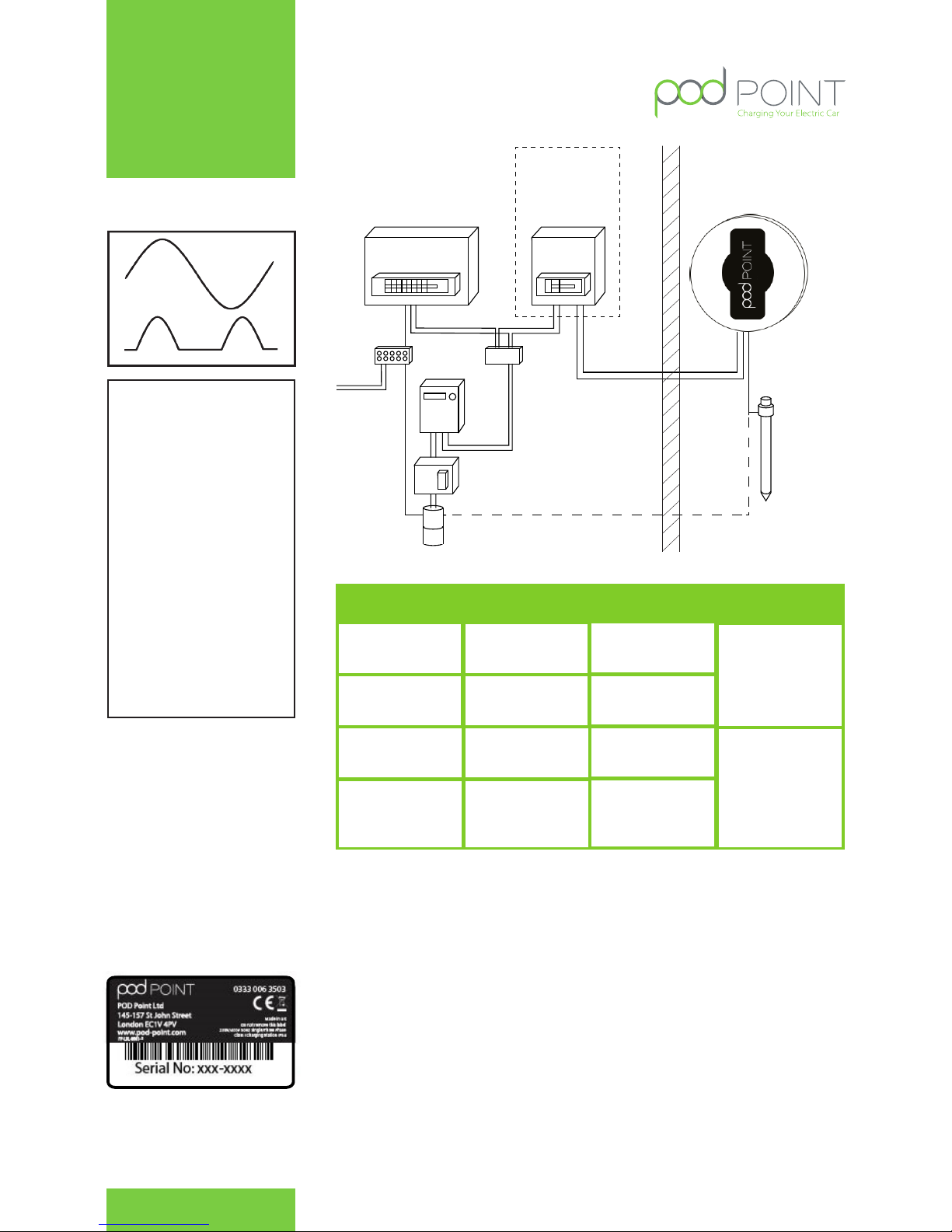
Array systems:
In case of several charging stations connected to the same power
supply line, an additional local ground connection will have to be
ensured in order at least , every 10 outlets. The maximum resistance
for each additional ground connection (taken independently) will
have to be less than 167 ohms. All the ground lines will have to be
connected to ensure a single equi – potential zone.
Transformers
If the earth is not achievable then a transformer is required. In Mode
IT or TT> 150 Ohms: An isolating transformer with separate windings
is placed upstream EVSE. This one must then be fed in mode TN. The
Neutral feed of the transformer shall be connected to PE before the
RCD and MCB (if 2 pole MCB is used), resistance measured between
the EVSE PE and this Earth must be less than 167 ohms.
Mode IT is prohibited
All installations must comply to BS7671 regulations.
Isolation and Switching for Security and
Maintenance
To ensure that the POD Point Solo unit can be “turned off” to enhance
security and enable maintenance and repair activity, a double
pole switch (or isolator) suitably rated shall be installed within the
customer’s property in an accessible location. The switch should be
mounted at a height of between 450mm and 1200mm above finished
floor level to achieve compliance with Building Reg’s. An isolator
switch is a mandatory required for “new builds”, but optional for
existing dwellings (for additional security at customers request).
Installation Procedure
The POD Point Solo has been designed as a wall mounted
device. The installer should confirm that the wall that the unit
is intended to be fixed to is structurally appropriate for the
mounting of the POD Point Solo. The installer should identify
the construction of the wall, and identify the correct and
appropriate fixings to use.
• The Installer has a duty of care to ensure that the POD
Point Solo unit is securely attached to the wall or
structure where the unit is intended to be operated
from.
• Once the location and height of the POD Point Solo
unit has been decided, the installer can begin marking
the wall with indicator points to locate the unit. Use drilling
template to locate the holes.
• Before drilling commences ensure that the installation
wall has been checked for electric cabling or pipework
with a suitable detector.
• It is highly recommended this is done prior to any
installation work commencement (drilling of fitting of
conduit etc) to allow the customer to visualise where
the unit will be installed. Once the installation site is
marked up, confirm with the customer this meets their
expectations.
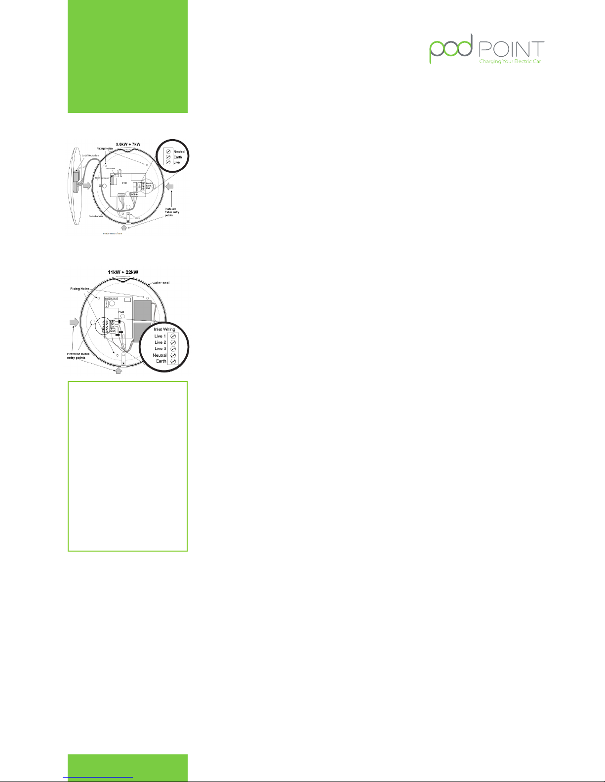
Drilling the Holes for the Electrical Supply
Cable Entry
As the electrical supply to the POD Point Solo may be fed from a
number of directions; the unit has been designed to accept supply
conduit entry on either the left or right sides or via rear entry (if supply
wiring has already been chased into the wall)
The installer should drill a suitable hole for the cable entry grommet/
adapter to be used to accept the electrical supply cables in EITHER the
left, right or rear of the unit (depending on direction that the electrical
supply approaches). Flat surfaces have been provided at either side
of the unit for ease of drilling. Once drilled the installer should fit an
appropriate cable gland or conduit adapter for the type of conduit
being used to supply the unit.
When drilling the case:
1. Only drill in the flat surfaces provided on the left, right or
rear of the unit. Do not drill on any curved surface.
2. Take care not to damage any wiring or components inside
the case. Place a suitable stop (e.g. block of wood) inside
the case when drilling to prevent accidental damage.
3. If any of the wiring or components are damaged during
installation DO NOT CONNECT OR SWITCH ON THE POWER
before consulting with POD Point.
4. The wall can now be drilled for the 3 mounting holes and
depending on the wall structure solid/dry lined or stud
partition, appropriate fixings can be used to fit the unit to
the wall. Do not drill with the unit in position as masonry
dust may damage the unit. Use the recommended drilling
template included in the box.
5. The rear of the unit should then be fitted to the wall by
fitting the top/upper screw first so the remaining 2 screws
positions can be easily aligned and fitted.
6. Once fitted in place, the rear unit should be securely fixed
flush to the wall.
POD Point July 2015
PP - D - 001
POD Point Technical Manual
Contact:
020 72477117
www.pod-point.com
4