TMB Solaris Mozart One User manual


Solaris Mozart One user manual version 1.2 041719
- 2 -
Introduction
PRODUCT OVERVIEW
Mozart One is controlled via DMX512 protocol with RDM functionality, allowing bidirectional feedback
controllers and devices over a standard DMX line. Mozart One’s compact size and low profile make it ideal
for stage sets and scenery.
Mozart One features one pixel comprised of six RGBW Cree®LEDs beneath single lens. A camera-friendly
1200 Hz refresh rate, 8-bit color dimming control, and three operating modes – 1 pixel WHITE (1 ch), 1 pixel
RGB (3 ch), and 1 pixel RGBW (4 ch) – make Mozart One the most versatile single-lens LED fixture
available.
•One RGBW, single-lens “pixel”
•1, 3, or 4 channels – White, RGB, or RGBW
•IP65 Rated. Dust and water resistant. Silent operation!
•Perfect for set lighting and stages
UNPACKING INSTRUCTIONS
Upon receipt of the fixture, carefully unpack the carton and check the contents to ensure that all parts are
present and in good condition. Notify the shipper immediately and retain packing material for inspection if
any parts appear to be damaged from shipping or if the carton itself shows signs of mishandling. Save the
carton and all packing materials. In the event that a fixture must be returned to the factory, it is important that
the fixture be returned in the original factory box and packing.
POWER REQUIREMENTS
Before powering the unit, make sure the line voltage is within the range of accepted voltages. This fixture
accommodates 100-240VAC, 50/60Hz, powered by an external Mozart Drive unit. All fixtures must be
powered directly from a switched circuit and cannot be operated with a rheostat (variable resistor) or dimmer
circuit, even if the rheostat or dimmer channel is used solely for a 0-100% switch.
When powered up, the fixture name and software version will show on the 7-segment display.

Solaris Mozart One user manual version 1.2 041719
- 3 -
FREQUENCY SETTINGS
Depending on location, change the Default Frequency setting to match the mains power (e.g. North America
should be set at 60Hz). Proper frequency setting will ensure minimum number of visible artifacts when using
Solaris on camera.
SAFETY INSTRUCTIONS
•Please keep this User Guide for future reference. If unit is sold to another user, make sure they also
receive this instruction booklet.
•Ensure fixture and Mozart Drive are connected to proper voltage, and that line voltage is not higher than
that stated on the fixture.
•Make sure there are no flammable materials close to the unit while operating.
•Always disconnect from the power source before servicing or fuse replacement. Always use the fuse
specified in this manual..
•Always use a safety cable when hanging fixture overhead.
•Maximum ambient temperature (Ta) is 40°C (104°F). Do not operate fixture at temperatures above this
rating.
•In the event of a serious operating problem, stop using the unit immediately. Repairs must be carried
out by trained, authroized personnel. Contact the nearest authorized technical assistance center. Only
OEM spare parts should be used.
•Do not connect the device to a dimmer pack.
•Make sure the 3-conductor Power+Data cord is never crimped or damaged.
•Never disconnect 3-conductor Power+Data cord by pulling or tugging on the cord.
•Avoid direct eye exposure to the light source during operation.
Caution! There are no user serviceable parts inside the unit. Do not open the housing or attempt
any repairs yourself. In the unlikely event your unit may require service, please contact your
distributor.
FUSE REPLACEMENT
The Mozart Drive PortableMount uses a 4A, 250V, slow-blow, 5x20mm (0.2x0.8 in.) fuse. Mozart One
fixtures have no fuse. To replace fuse:
1. With a screwDriver turn the fuse cap counter-clockwise to remove fuse cap with fuse.
2. Replace fuse attached to fuse cap.
3. Reinsert fuse cap with new fuse and tighten clockwise.
Please read these instructions carefully. This user guide
contains important information about the installation, usage
and maintenance of this product.
Disconnect the power cord before replacing a
fuse and always replace with the same type fuse.
Solaris Mozart One user manual version 1.2 041719
- 4 -
MOUNTING/RIGGING –MOZART DRIVE,PORTABLEMOUNT
Orientation
The Mozart Drive PortableMount may be mounted on truss or pipe, in any position, using the yoke supplied
with the unit. Always make sure there is adequate room for ventilation.
Rigging – Always consult a certified rigging engineer before suspending any fixture
overhead!
Use ProBurger®couplers or equivalent C- or O-type clamps for attaching to truss. After
establishing the desired position, retighten both knobs.
•Always use safety cables!
•When selecting installation location, consider routine maintenance.
•Never mount Mini enclosure where it will be exposed to moisture, high humidity,
extreme temperatures, or restricted ventilation.
Setup
A DMX data link is needed to run light shows of one or more fixtures using a DMX-512 lighting console. The
combined number of channels required by all of the fixtures on the DMX data link will determine the number
of fixtures the DMX data link can support.
Important: Fixtures on a DMX data link must be daisy-chained in one single line. To comply with the EIA-
485 standard, no more than 32 devices should be connected on one data link. Connecting more than 32
fixtures on one serial data link without the use of a DMX optically isolated splitter may result in deterioration
of the digital DMX signal.
Maximum recommended DMX data link distance between fixtures: 300 meters (984 ft.)
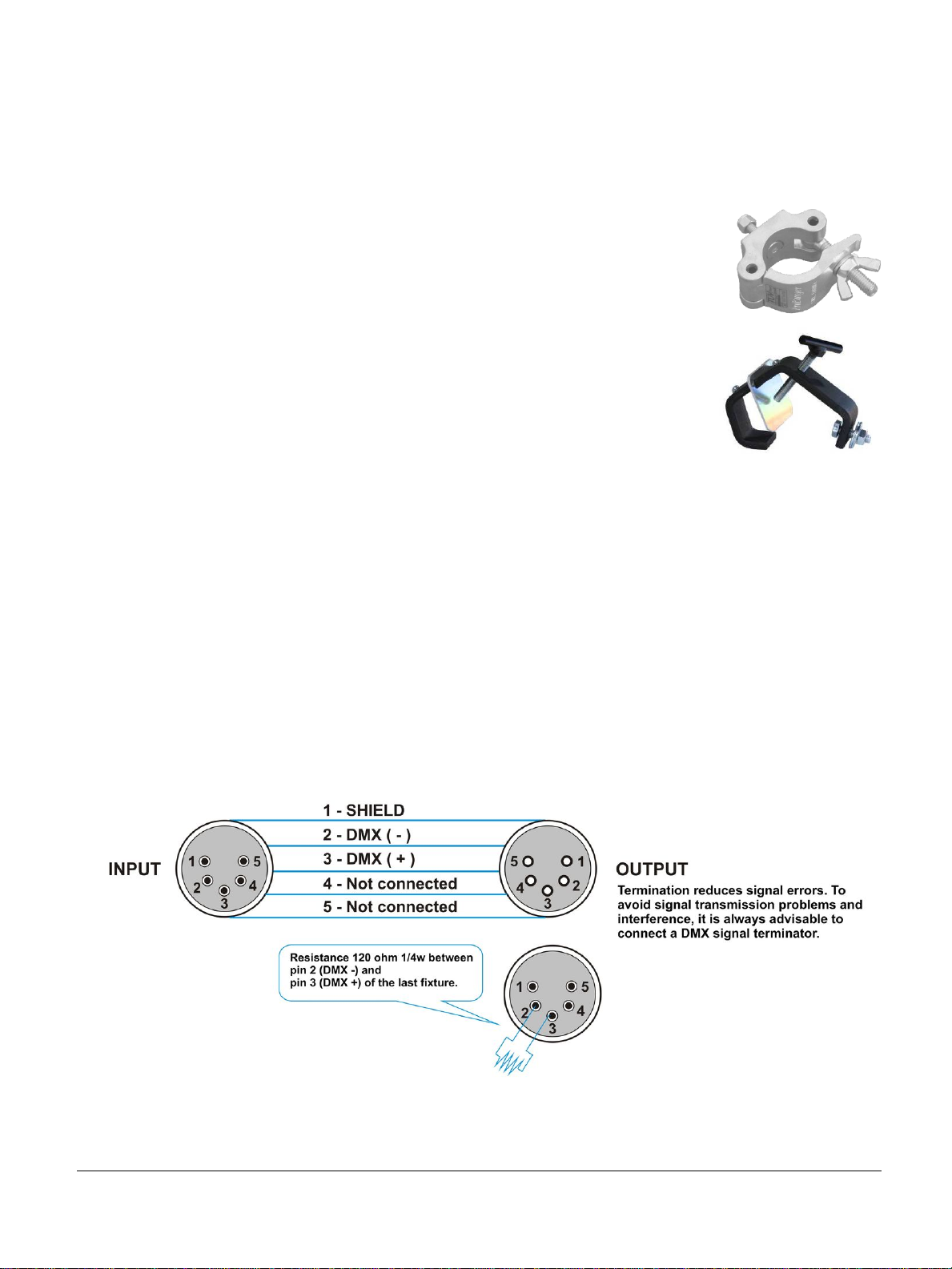
DMX CONNECTOR CONFIGURATION FOR THE MOZART DRIVE

Solaris Mozart One user manual version 1.2 041719
- 5 -
Do not allow contact between the common and the fixture’s chassis
ground. Grounding the common can cause a ground loop, and your fixture
may perform erratically. Test cables with an ohm meter to verify correct
polarity and to make sure the pins are not grounded or shorted to the shield
or each other.
SETTING UP A DMX SERIAL LINK
1. Connect the (male) 5-pin connector side of the DMX cable to the output (female) 5-pin connector of the
DMX console.
2. Connect the opposite end of the cable (female) to the input connector of the Mozart Drive consisting of a
(male) 5-pin connector.
3. Proceed to connect from the Drive output as stated above to the input of the following Drive and so on.
4. Continue linking until the last fixture is conected in your DMX chain.
FIXTURE LINKING

Solaris Mozart One user manual version 1.2 041719
- 6 -
Operating Instructions
PIXEL MAP
Mozart One consists of six Cree XM-L LEDs beneath a single lens. There are three control modes for
Solaris Mozart One fixtures:
1) White: 1-pixel unit (1-channel mode)
2) RGB: 1-pixel unit (3-channel mode)
3) RGBW: 1-pixel unit (4-channel mode)
Modes can be changed within the Mozart Drive via RDM protocol.
INTERNAL ADDRESS SET
The external Mozart Drive has a user definable DMX starting address, adjusted via RDM.
Additionally, each Mozart One also has an independent ID that will indicate its position in the DMX universe.
Each connected Mozart One can be given an indpedent ID number, or they can all be the same (up to 10
fixtures linked in Regular mode; 5 fixtures linked in HiPower Mode).
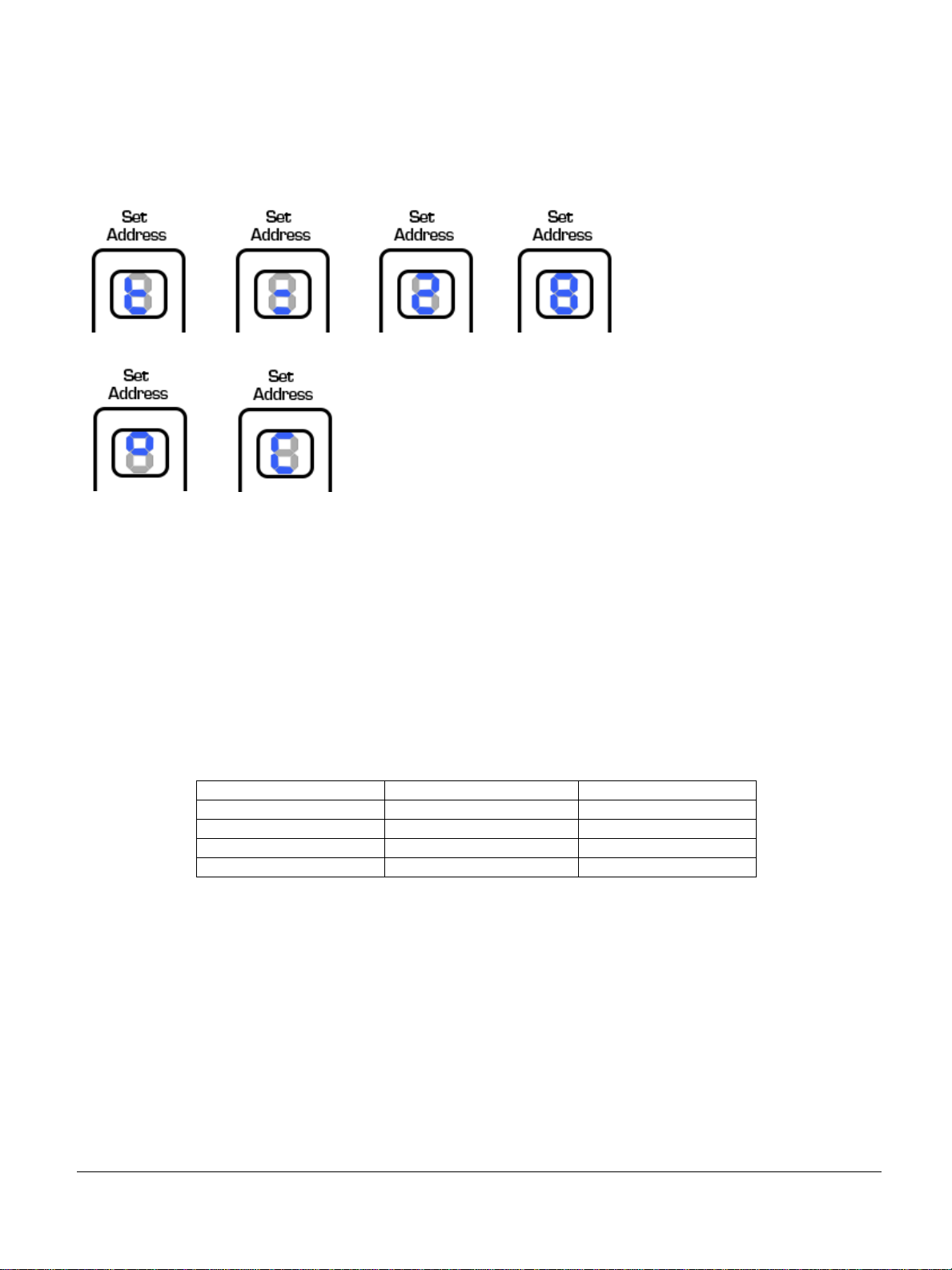
Follow these steps to set the internal fixture ID of Mozart One fixtures (1-10 in Regular mode, or 1-5
in HiPower mode)
Press and hold <Set Address> button located at the back of the Mozart.

Solaris Mozart One user manual version 1.2 041719
- 7 -
The internal fixture ID will appear (1-10).
To change this number, press the <Set Address> button again. The next ID number will appear. Repeat until
the desired ID number is shown on the 7-segment display.
Using “DMX 1” for a starting address on the Mozart Drive, following are examples of the Mozart One fixture
ID:
DMX CH
FIXTURE ID
1 PIX
1
W
1
2
W
2
3
W
3
DMX CH
FIXTURE ID
1 PIX
1
2
3
R
G
B
1
4
5
6
R
G
B
2
7
8
9
R
G
B
3
DMX CH
FIXTURE ID
1 PIX
1
2
3
4
R
G
B
W
1
5
6
7
8
R
G
B
W
2
9
10
11
12
R
G
B
W
3
Continue as necessary . . .
Solaris Mozart One user manual version 1.2 041719
- 8 -
TEMPERATURE
To check the temperature of the Mozart One, tap the address set button and the 7-segment display will show
the temperature (e.g. 28 °C):
Appendix
RDM FUNCTIONALITY
Mozart Drives have RDM functionality. Below are the RDM functions available in these devices. TMB has
many options for RDM control of your devices: ProPlex RDMigo and IQ RDM Manager Software; ProPlex
Striker; and ProPlex MasterFade. Additionally, ProPlex RDM Opto-Splitters and the ProPlex IQ product
range offer many means of RDM over DMX data distribution.
Main
Voltage (V)
Current (A)
Mode
Present value
Present value
DMX address
Highest value
Highest value
RDM version
Lowest value
Lowest value
Software version
GENERAL MAINTENANCE
To maintain optimum performance and minimize wear fixtures should be cleaned frequently. Usage and
environment are contributing factors in determining frequency. As a general rule, fixtures should be
cleaned at least twice a month. Dust build up reduces light output performance and can cause
overheating. This can lead to reduced lamp life and increased mechanical wear. Be sure to disconnect
power to the fixture before conducting maintenance.
Unplug fixture from power. Use a vacuum or air compressor and a soft brush to remove dust
collected on external vents and internal components. Clean all glass when the fixture is cold with a mild
solution of glass cleaner or Isopropyl Alcohol and a soft lint free cotton cloth or lens tissue. Apply solution to
the cloth or tissue and drag dirt and grime to the outside of the lens. Gently polish optical surfaces until they
are free of haze and lint.

Solaris Mozart One user manual version 1.2 041719
- 9 -
The cleaning of internal and external optical lenses and/or mirrors must be carried out periodically to
optimize light output. Cleaning frequency depends on the environment in which the fixture operates: damp,
smoky or particularly dirty surroundings can cause greater accumulation of dirt on the unit’s optics. Clean
with soft cloth using normal glass cleaning fluid. Always dry the parts carefully. Clean the external optics
at least every 20 days. Clean the internal optics at least every 30 to 60 days.
LIMITED WARRANTY
Solaris LED fixtures (the Product) are warranted by TMB against defective materials or workmanship
for a period of two (2) years from the date of original sale by TMB.
TMB’s warranty shall be restricted to the repair or replacement of any part that proves to be defective
and for which a claim is submitted to TMB before the expiration of the applicable warranty periods.
This Limited Warranty is void if the defects of the Product are the result of:
•Opening the casing, repair, or adjustment by anyone other than TMB or persons specifically
authorized by TMB
•Accident, physical abuse, mishandling, or misapplication of the product.
•Damage due to lightning, earthquake, flood, terrorism, war, or act of God.
TMB will not assume responsibility for any labor expended, or materials used, to replace and/or repair
the Product without TMB’s prior written authorization. Any repair of the Product in the field, and any
associated labor charges, must be authorized in advance by TMB. Freight costs on warranty repairs
are split 50/50: Customer pays to ship defective product to TMB; TMB pays to ship repaired product,
ground freight, back to Customer.
This warranty DOES NOT cover consequential damages or costs of any kind.
A Return Merchandise Authorization (RMA) Number must be obtained from TMB prior to return of any
defective merchandise for warranty or non-warranty repair. For all repairs please contact TMB Tech
Support Repair using the contact information below or email TechSupportRepairNA@tmb.com.
527 Park Ave., San Fernando, CA 91340
Tel: +1 818.899.8818
Fax: +1 818.899.8813
tmb-i[email protected]om
www.tmb.com
RETURN PROCEDURE
Returned merchandise must be sent prepaid and in the original packing, call tags will not be issued.
Package must be clearly labeled with a Return Merchandise Authorization Number (RMA #). Products
returned without an RMA # will be refused. Please contact TMB and request RMA # prior to shipping the
fixture. Be prepared to provide the model number, serial number and a brief description of the cause for
the return. Be sure to properly pack fixture, any shipping damage resulting from inadequate packaging is
the customer’s responsibility. TMB reserves the right to use its own discretion to repair or replace
product(s). As a suggestion, proper UPS packing or double-boxing is always a safe method to use.
Note: If you are given an RMA #, please include the following information on a piece of paper inside
the box:
1) Your name
2) Your address
3) Your phone number
4) The RMA #
5) A brief description of the symptoms
Solaris Mozart One user manual version 1.2 041719
- 10 -
MOZART ONE –TECHNICAL SPECIFICATIONS
Mozart ONE
LED Light sources
6 Cree LEDs (single lens)
Pixels per fixture
1
DMX Channels per fixture
1, 3, 4
Color LEDs
RGBW
Color Mode
White, RGB, RGBW
Refresh rate
1200 HZ
Intensity Control
8 bit
Control
Mozart Drive
DC power
48 VDC
Power Consumption
20 W or 40 W (HiPower mode)
Cooling
Convection
IP Rating
IP65
Operating Temperature
-20°C - +40°C
Control/Power Connectors
In/Out - Amphenol M12
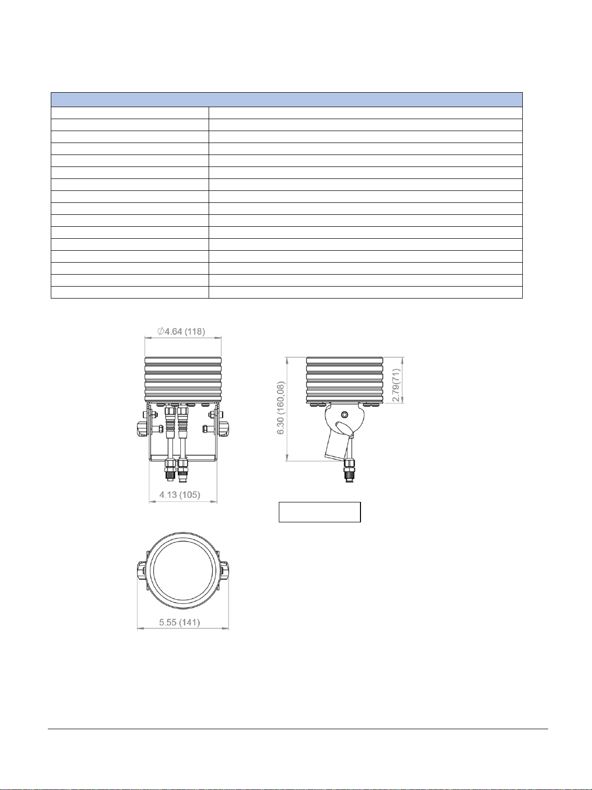
Dimensions (HxWxD)
4.6 x 5.6 x 6.3 in (118 x 141 x 160 mm)
Weight
3.74 lb. (1.7 kg)
Inches (mm)

Solaris Mozart One user manual version 1.2 041719
- 11 -
MOZART DRIVE PORTABLEMOUNT –TECHNICAL SPECIFICATIONS
Mozart Drive PortableMount
Control
DMX-512 with RDM
DMX channels
3, 12, 48
DMX input
Locking 5-pin XLR male socket
DMX output (linking)
Locking 5-pin XLR female socket
DMX output (Mozart One)
10 max. (5 max. high power mode)
Power IN
100-240 VAC
Power OUT (Mozart One)
48 VDC
Power Consumption
200 W max (10 Mozart Ones @ standard power)
Cooling
Convection
IP Rating
IP20
Operating Temperature
-4 to +104 °F (-20 to +40 °C)
Control/Power Connectors
In/Out - Amphenol M12
Dimensions w/yoke (HxWxD)
5.3 x 7.9 x 10.7 in (135 x 202 x 272 mm)
Dimensions w/o yoke (HxWxD)
3.4 x 7.7 x 10.7 in (87 x 196 x 272 mm)
Weight
9.85 lb (4.5 kg)
Table of contents
Other TMB Lighting Equipment manuals


