TMB FloppyFlex User manual

USER MANUAL
TMB 24/7 Technical Support
US/Canada: +1 818.794.1286
Toll Free: 1 877.862.3833 (877.TMB.DUDE)
UK: +44 (0)20.8574.9739
Toll Free: 0800.652.5418
e-mail: techsuppor[email protected]

FloppyFlex User Manual Version 2.0 - 22 August 2022 - 2 -
FloppyFlex User Manual
FloppyFlex-Manual-v2.0
Effective 22 August 2022
© Copyright 2022, TMB
All rights reserved
TMB authorizes its customers to download and print this
electronically published manual for professional use only. TMB
prohibits reproduction, modification or distribution of this document
for any other purposes, without express written consent.
Specifications are subject to change without notice. The information
in this document supersedes all previously supplied information
before the effective date listed above. TMB has confidence in the
accuracy of the document information herein but assumes no
responsibility or liability for any loss occurring as a direct or indirect
result of errors or exclusions whether by accident or any other cause.

FloppyFlex User Manual Version 2.0 - 22 August 2022 - 3 -
LIMITED WARRANTY ..................................................................................................................................................................4
PRODUCT OVERVIEW .................................................................................................................................................................5
LARGE 270° PROFILE |STS –GENERAL SPECIFICATIONS.............................................................................................................................6
SMALL 160° PROFILE |STS –GENERAL SPECIFICATIONS ............................................................................................................................7
FLAT 160° PROFILE |FTB –GENERAL SPECIFICATIONS ..............................................................................................................................8
FLAT 160° PROFILE |STS –GENERAL SPECIFICATIONS...............................................................................................................................9
MINI 120° PROFILE |FTB –GENERAL SPECIFICATIONS............................................................................................................................10
MINI 120° PROFILE |STS –GENERAL SPECIFICATIONS ............................................................................................................................10
CARE AND HANDLING............................................................................................................................................................... 11
CUTTING FLOPPYFLEX............................................................................................................................................................... 14
MINI TOOL KIT .................................................................................................................................................................................14
CUTTING MARKS ...............................................................................................................................................................................14
TERMINATING FLOPPYFLEX ...................................................................................................................................................... 16
SIDE NUMBERING SYSTEM ..................................................................................................................................................................16
EZ CONNECT SYSTEM.........................................................................................................................................................................16
INSERTING THE SPREADER ...................................................................................................................................................................17
EZ CONNECT TERMINATION INSTRUCTIONS ............................................................................................................................................18
MOUNTING FLOPPYFLEX .......................................................................................................................................................... 22
ALUMINUM MOUNTING PROFILES ........................................................................................................................................................22
ALUMINUM PROFILE INSTALLATION GUIDELINES......................................................................................................................................25
FREQUENTLY ASKED QUESTIONS.............................................................................................................................................. 31
LEAD-IN LENGTHS..................................................................................................................................................................... 33
RETURN PROCEDURE................................................................................................................................................................ 34

FloppyFlex User Manual Version 2.0 - 22 August 2022 - 4 -
LIMITED WARRANTY
FloppyFlex is warranted by TMB against defective materials or workmanship for a period of three (3) years
from the date of original sale by TMB.
TMB’s warranty shall be restricted to the repair or replacement of any part that proves to be defective and for
which a claim is submitted to TMB before the expiration of the applicable warranty periods.
This Limited Warranty is void if the defects of the Product are the result of:
•Opening the casing, repair, or adjustment by anyone other than TMB or persons specifically authorized by
TMB
•Accident, physical abuse, mishandling, or misapplication of the product.
•Damage due to lightning, earthquake, flood, terrorism, war, or act of God.
TMB will not assume responsibility for any labor expended, or materials used, to replace and/or repair the
Product without TMB’s prior written authorization. Any repair of the Product in the field, and any associated
labor charges, must be authorized in advance by TMB. Freight costs on warranty repairs are split 50/50:
Customer pays to ship defective product to TMB; TMB pays to ship repaired product, ground freight, back to
Customer.
This warranty does not cover consequential damages or costs of any kind.
A Return Merchandise Authorization (RMA) Number must be obtained from TMB prior to return of any defective
merchandise for warranty or non-warranty repair. For all repairs please contact TMB Tech Support Repair using
the contact information below or email TechSupportRepairNA@tmb.com.
US UK
527 Park Ave. 21 Armstrong Way
San Fernando, CA 91340 Southall, UB2 4SD England
Tel: +1 818.899.8818 Tel: +44 (0)20.8574.9700
Fax: +1 818.899.8813 Fax: +44 (0)20.8574.9701
tmb-info@tmb.com tmb-info@tmb.com
www.tmb.com www.tmb.com

FloppyFlex User Manual Version 2.0 - 22 August 2022 - 5 -
PRODUCT OVERVIEW
FloppyFlex and FloppyFlex Digital are world class professional grade, flexible IP68*, IP67 and IP20 LED “neon”. It’s
the perfect replacement for glass neon, easy to use, long lasting & durable. Suitable for many projects and
installations including indoor, outdoor, signage & architectural. Single Color, RGB, Digital RGB, Digital RGBW and
Dynamic White with side-to-side (STS) and front-to-back (FTB) bend options.
*IP68 Rated configurations available by special order
FloppyFlex
•Easy to use and install.
•Wide range of accessories for joining, terminating, mounting, and powering.
•Available in RGB, White (2100, 2500, 2700, 3000, 3500, 4000, 4500, 5000, 5700, 6500K)
Red, Green, Blue, Yellow, Amber, and Orange
•Large 270°, Small and Flat 160° STS bend; Flat 160° FTB bend versions.
•Custom colors available.
FloppyFlex Digital
•Smooth soft edges, seamless color blending.
•Auto-addressing allows for quick setup and patching.
•Large 270° and Small 160° STS bend; Flat 160° FTB bend versions.
•Available in Digital RGB and RGBW, with multi-pixel control.
•Unlimited and unprecedented possibilities.
FloppyFlex User Manual Version 2.0 - 22 August 2022 - 6 -
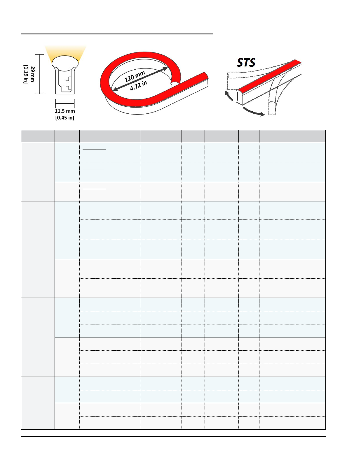
LARGE 270° PROFILE |STS –GENERAL SPECIFICATIONS
Category Housing Color Options
Minimum Cut
Length
Voltage
Operating
Temp
Wiring Control
White Light
PVC
Epistar LED
2100K, 2700K, 3000K,
3500K, 4000K, 5700K
83.34 mm [3.28 in]
[6 LEDs] 24 VDC -20 to 45 °C
[-4 to 113 °F] 2-wire DMX via FloppyDrive 2x2
Line-side MLV Dimming (with
compatible transformer)
Nichia LED
2500K, 2700K, 3000K,
3500K, 4000K, 4500K, 5000K
100 mm [3.94 in]
[6 LEDs] 24 VDC -20 to 45 °C
[-4 to 113 °F] 2-wire DMX via FloppyDrive 2x2
Line-side MLV Dimming (with
compatible transformer)
Silicone Epistar LED
2100K, 2700K, 3000K,
3500K, 4000K, 5700K
83.34 mm [3.28 in]
[6 LEDs] 24 VDC -40 to 55 °C
[-40 to 131 °F] 2-wire DMX via FloppyDrive 2x2
Line-side MLV Dimming (with
compatible transformer)
Colorful Light
PVC
Red 125 mm [4.92 in]
[9 LEDs] 24 VDC -20 to 50 °C
[-4 to 122 °F] 2-wire DMX via FloppyDrive 2x2
Line-side MLV Dimming (with
compatible transformer)
Green, Blue, Yellow, Orange 83.34 mm [3.28 in]
[6 LEDs] 24 VDC -20 to 45 °C
[-4 to 113 °F] 2-wire DMX via FloppyDrive 2x2
Line-side MLV Dimming (with
compatible transformer)
Pink, Purple 100 mm [3.94 in]
24 VDC TBD 2-wire DMX via FloppyDrive 2x2
Line-side MLV Dimming (with
compatible transformer)
Silicone
Red, Amber 125 mm [4.92 in]
[9 LEDs] 24 VDC -40 to 60 °C
[-40 to 140 °F] 2-wire DMX via FloppyDrive 2x2
Line-side MLV Dimming (with
compatible transformer)
Green, Blue 83.34 mm [3.28 in]
[6 LEDs] 24 VDC -40 to 55 °C
[-40 to 131 °F] 2-wire DMX via FloppyDrive 2x2
Line-side MLV Dimming (with
compatible transformer)
Variable Color
PVC
RGB 100 mm [3.94 in]
[6 LEDs] 24 VDC -20 to 45 °C
[-4 to 113 °F] 4-wire DMX via FloppyDrive 4x2
RGBW 100 mm [3.94 in]
[6 LEDs] 24 VDC -20 to 35 °C
[-4 to 95 °F] 5-wire DMX via FloppyDrive 5x2
Dynamic White 2200K-5700K 83.34 mm [3.28 in]
[12 LEDs] 24 VDC -20 to 45 °C
[-4 to 113 °F] 3-wire DMX via FloppyDrive 3x2
Silicone
RGB 100 mm [3.94 in]
[6 LEDs] 24 VDC -40 to 55 °C
[-40 to 131 °F] 4-wire DMX via FloppyDrive 4x2
RGBW 100 mm [3.94 in]
[6 LEDs] 24 VDC -40 to 45 °C
[-40 to 113 °F] 5-wire DMX via FloppyDrive 5x2
Dynamic White 2200K-5700K 83.34 mm [3.28 in]
[12 LEDs] 24 VDC -40 to 55 °C
[-40 to 131 °F] 3-wire DMX via FloppyDrive 3x2
Digital Pixel
PVC RGB 125 mm [4.92 in]
[7 LEDs] 24 VDC -20 to 45 °C
[-4 to 113 °F] 3-wire DMX via FloppyDrive Digital
RGBW 125 mm [4.92 in]
[7 LEDs] 24 VDC -20 to 35 °C
[-4 to 95 °F] 3-wire DMX via FloppyDrive Digital
Silicone RGB 125 mm [4.92 in]
[7 LEDs] 24 VDC -40 to 55 °C
[-40 to 131 °F] 3-wire DMX via FloppyDrive Digital
RGBW 125 mm [4.92 in]
[7 LEDs] 24 VDC -40 to 55 °C
[-40 to 131 °F] 3-wire DMX via FloppyDrive Digital
FloppyFlex User Manual Version 2.0 - 22 August 2022 - 7 -
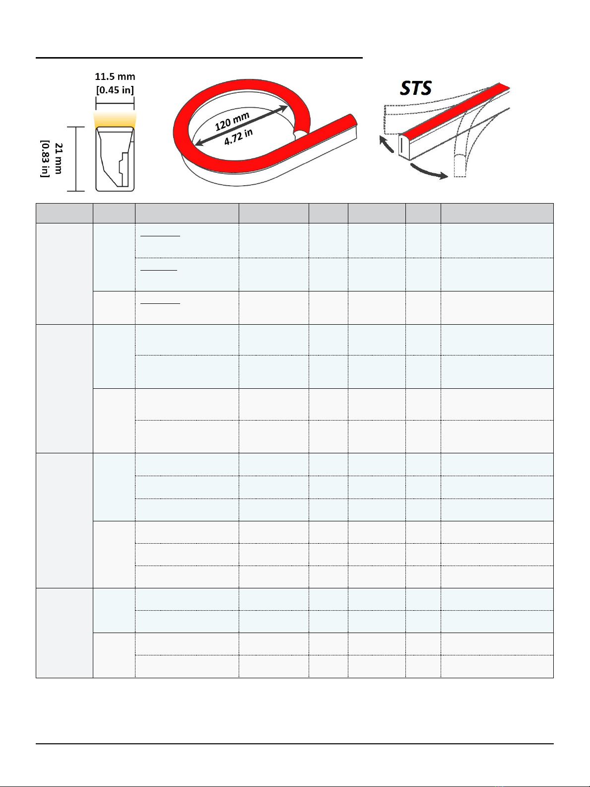
SMALL 160° PROFILE |STS –GENERAL SPECIFICATIONS
Category Housing Color Options
Minimum Cut
Length
Voltage
Operating
Temp
Wiring Control
White Light
PVC
Epistar LED
2100K, 2700K, 3000K,
3500K, 4000K, 5700K
83.34 mm [3.28 in]
[6 LEDs] 24 VDC -20 to 45 °C
[-4 to 113 °F] 2-wire DMX via FloppyDrive 2x2
Line-side MLV Dimming (with
compatible transformer)
Nichia LED
2500K, 2700K, 3000K,
3500K, 4000K, 4500K, 5000K
100 mm [3.94 in]
[6 LEDs] 24 VDC -20 to 45 °C
[-4 to 113 °F] 2-wire DMX via FloppyDrive 2x2
Line-side MLV Dimming (with
compatible transformer)
Silicone Epistar LED
2100K, 2700K, 3000K,
3500K, 4000K, 5700K
83.34 mm [3.28 in]
[6 LEDs] 24 VDC -40 to 55 °C
[-40 to 131 °F] 2-wire DMX via FloppyDrive 2x2
Line-side MLV Dimming (with
compatible transformer)
Colorful Light
PVC
Red 125 mm [4.92 in]
[9 LEDs] 24 VDC -20 to 50 °C
[-4 to 122 °F] 2-wire DMX via FloppyDrive 2x2
Line-side MLV Dimming (with
compatible transformer)
Green, Blue, Yellow, Orange 83.34 mm [3.28 in]
[6 LEDs] 24 VDC -20 to 45 °C
[-4 to 113 °F] 2-wire DMX via FloppyDrive 2x2
Line-side MLV Dimming (with
compatible transformer)
Silicone
Red, Amber 125 mm [4.92 in]
[9 LEDs] 24 VDC -40 to 60 °C
[-40 to 140 °F] 2-wire DMX via FloppyDrive 2x2
Line-side MLV Dimming (with
compatible transformer)
Green, Blue 83.34 mm [3.28 in]
[6 LEDs] 24 VDC -40 to 55 °C
[-40 to 131 °F] 2-wire DMX via FloppyDrive 2x2
Line-side MLV Dimming (with
compatible transformer)
Variable Color
PVC
RGB 100 mm [3.94 in]
[6 LEDs] 24 VDC -20 to 45 °C
[-4 to 113 °F] 4-wire DMX via FloppyDrive 4x2
RGBW 100 mm [3.94 in]
[6 LEDs] 24 VDC -20 to 35 °C
[-4 to 95 °F] 5-wire DMX via FloppyDrive 5x2
Dynamic White 2200K-5700K 83.34 mm [3.28 in]
[12 LEDs] 24 VDC -20 to 45 °C
[-4 to 113 °F] 3-wire DMX via FloppyDrive 3x2
Silicone
RGB 100 mm [3.94 in]
[6 LEDs] 24 VDC -40 to 55 °C
[-40 to 131 °F] 4-wire DMX via FloppyDrive 4x2
RGBW 100 mm [3.94 in]
[6 LEDs] 24 VDC -40 to 45 °C
[-40 to 113 °F] 5-wire DMX via FloppyDrive 5x2
Dynamic White 2200K-5700K 83.34 mm [3.28 in]
[12 LEDs] 24 VDC -40 to 55 °C
[-40 to 131 °F] 3-wire DMX via FloppyDrive 3x2
Digital Pixel
PVC RGB 125 mm [4.92 in]
[7 LEDs] 24 VDC -20 to 45 °C
[-4 to 113 °F] 3-wire DMX via FloppyDrive Digital
RGBW 125 mm [4.92 in]
[7 LEDs] 24 VDC -20 to 35 °C
[-4 to 95 °F] 3-wire DMX via FloppyDrive Digital
Silicone RGB 125 mm [4.92 in]
[7 LEDs] 24 VDC -40 to 55 °C
[-40 to 131 °F] 3-wire DMX via FloppyDrive Digital
RGBW 125 mm [4.92 in]
[7 LEDs] 24 VDC -40 to 55 °C
[-40 to 131 °F] 3-wire DMX via FloppyDrive Digital

FloppyFlex User Manual Version 2.0 - 22 August 2022 - 8 -
FLAT 160° PROFILE |FTB –GENERAL SPECIFICATIONS
Category Housing Color Options
Minimum Cut
Length
Voltage
Operating
Temp
Wiring Control
White Light
PVC
Epistar LED
2100K, 2700K, 3000K,
3500K, 4000K, 5700K
83.34 mm [3.28 in]
[6 LEDs] 24 VDC -20 to 45 °C
[-4 to 113 °F] 2-wire DMX via FloppyDrive 2x2
Line-side MLV Dimming (with
compatible transformer)
Nichia LED
2500K, 2700K, 3000K,
3500K, 4000K, 4500K, 5000K
100 mm [3.94 in]
[6 LEDs] 24 VDC -20 to 45 °C
[-4 to 113 °F] 2-wire DMX via FloppyDrive 2x2
Line-side MLV Dimming (with
compatible transformer)
Silicone
Epistar LED
2100K, 2700K, 3000K,
3500K, 4000K, 5700K
83.34 mm [3.28 in]
[6 LEDs] 24 VDC -40 to 55 °C
[-40 to 131 °F] 2-wire DMX via FloppyDrive 2x2
Line-side MLV Dimming (with
compatible transformer)
Nichia LED
2500K, 2700K, 3000K,
3500K, 4000K, 4500K, 5000K
100 mm [3.94 in]
[6 LEDs] 24 VDC -20 to 45 °C
[-4 to 113 °F] 2-wire DMX via FloppyDrive 2x2
Line-side MLV Dimming (with
compatible transformer)
Colorful Light
PVC
Red, Amber 125 mm [4.92 in]
[9 LEDs] 24 VDC -20 to 50 °C
[-4 to 122 °F] 2-wire DMX via FloppyDrive 2x2
Line-side MLV Dimming (with
compatible transformer)
Green, Blue 83.34 mm [3.28 in]
[6 LEDs] 24 VDC -20 to 45 °C
[-4 to 113 °F] 2-wire DMX via FloppyDrive 2x2
Line-side MLV Dimming (with
compatible transformer)
Silicone
Red, Amber 125 mm [4.92 in]
[9 LEDs] 24 VDC -40 to 60 °C
[-40 to 140 °F] 2-wire DMX via FloppyDrive 2x2
Line-side MLV Dimming (with
compatible transformer)
Green, Blue 83.34 mm [3.28 in]
[6 LEDs] 24 VDC -40 to 55 °C
[-40 to 131 °F] 2-wire DMX via FloppyDrive 2x2
Line-side MLV Dimming (with
compatible transformer)
Variable Color
PVC
RGB 100 mm [3.94 in]
[6 LEDs] 24 VDC -20 to 45 °C
[-4 to 113 °F] 4-wire DMX via FloppyDrive 4x2
RGBW 100 mm [3.94 in]
[6 LEDs] 24 VDC -20 to 35 °C
[-4 to 95 °F] 5-wire DMX via FloppyDrive 5x2
Dynamic White 2200K-5700K 83.34 mm [3.28 in]
[12 LEDs] 24 VDC -20 to 45 °C
[-4 to 113 °F] 3-wire DMX via FloppyDrive 3x2
Silicone
RGB 100 mm [3.94 in]
[6 LEDs] 24 VDC -40 to 55 °C
[-40 to 131 °F] 4-wire DMX via FloppyDrive 4x2
RGBW 100 mm [3.94 in]
[6 LEDs] 24 VDC -40 to 45 °C
[-40 to 113 °F] 5-wire DMX via FloppyDrive 5x2
Dynamic White 2200K-5700K 83.34 mm [3.28 in]
[12 LEDs] 24 VDC -40 to 55 °C
[-40 to 131 °F] 3-wire DMX via FloppyDrive 3x2
Digital Pixel
PVC RGB 125 mm [4.92 in]
[7 LEDs] 24 VDC -20 to 45 °C
[-4 to 113 °F] 3-wire DMX via FloppyDrive Digital
RGBW 125 mm [4.92 in]
[7 LEDs] 24 VDC -20 to 35 °C
[-4 to 95 °F] 3-wire DMX via FloppyDrive Digital
Silicone RGB 125 mm [4.92 in]
[7 LEDs] 24 VDC -40 to 55 °C
[-40 to 131 °F] 3-wire DMX via FloppyDrive Digital
RGBW 125 mm [4.92 in]
[7 LEDs] 24 VDC -40 to 55 °C
[-40 to 131 °F] 3-wire DMX via FloppyDrive Digital

FloppyFlex User Manual Version 2.0 - 22 August 2022 - 9 -
FLAT 160° PROFILE |STS –GENERAL SPECIFICATIONS
Category Housing Color Options
Minimum Cut
Length
Voltage
Operating
Temp
Wiring Control
White Light
PVC
Epistar LED
2100K, 2700K, 3000K,
3500K, 4000K, 5700K
83.34 mm [3.28 in]
[6 LEDs] 24 VDC -20 to 45 °C
[-4 to 113 °F] 2-wire DMX via FloppyDrive 2x2
Line-side MLV Dimming (with
compatible transformer)
Nichia LED
2500K, 2700K, 3000K,
3500K, 4000K, 4500K, 5000K
100 mm [3.94 in]
[6 LEDs] 24 VDC -20 to 45 °C
[-4 to 113 °F] 2-wire DMX via FloppyDrive 2x2
Line-side MLV Dimming (with
compatible transformer)
Silicone
Epistar LED
2100K, 2700K, 3000K,
3500K, 4000K, 5700K
83.34 mm [3.28 in]
[6 LEDs] 24 VDC -40 to 55 °C
[-40 to 131 °F] 2-wire DMX via FloppyDrive 2x2
Line-side MLV Dimming (with
compatible transformer)
Nichia LED
2500K, 2700K, 3000K,
3500K, 4000K, 4500K,
5000K, 5700K
100 mm [3.94 in]
[6 LEDs] 24 VDC -20 to 45 °C
[-4 to 113 °F] 2-wire DMX via FloppyDrive 2x2
Line-side MLV Dimming (with
compatible transformer)
Colorful Light
PVC
Red, Amber 125 mm [4.92 in]
[9 LEDs] 24 VDC -20 to 50 °C
[-4 to 122 °F] 2-wire DMX via FloppyDrive 2x2
Line-side MLV Dimming (with
compatible transformer)
Green, Blue 83.34 mm [3.28 in]
[6 LEDs] 24 VDC -20 to 45 °C
[-4 to 113 °F] 2-wire DMX via FloppyDrive 2x2
Line-side MLV Dimming (with
compatible transformer)
Silicone
Red, Amber 125 mm [4.92 in]
[9 LEDs] 24 VDC -40 to 60 °C
[-40 to 140 °F] 2-wire DMX via FloppyDrive 2x2
Line-side MLV Dimming (with
compatible transformer)
Green, Blue 83.34 mm [3.28 in]
[6 LEDs] 24 VDC -40 to 55 °C
[-40 to 131 °F] 2-wire DMX via FloppyDrive 2x2
Line-side MLV Dimming (with
compatible transformer)

FloppyFlex User Manual Version 2.0 - 22 August 2022 - 10 -
MINI 120° PROFILE |FTB –GENERAL SPECIFICATIONS
Category Housing Color Options
Minimum Cut
Length
Voltage
Operating
Temp
Wiring Control
White Light
PVC Epistar LED
2100K, 2700K, 3000K,
3500K, 4000K, 5700K
83.34 mm [3.28 in]
[6 LEDs] 24 VDC -20 to 45 °C
[-4 to 113 °F] 2-wire DMX via FloppyDrive 2x2
Line-side MLV Dimming (with
compatible transformer)
Silicone Epistar LED
2100K, 2700K, 3000K,
3500K, 4000K, 5700K
83.34 mm [3.28 in]
[6 LEDs] 24 VDC -40 to 55 °C
[-40 to 131 °F] 2-wire DMX via FloppyDrive 2x2
Line-side MLV Dimming (with
compatible transformer)
Colorful Light
PVC Red, Green, Blue, Amber 125 mm [4.92 in]
[9 LEDs] 24 VDC -20 to 50 °C
[-4 to 122 °F] 2-wire DMX via FloppyDrive 2x2
Line-side MLV Dimming (with
compatible transformer)
Silicone Red, Green, Blue, Amber 125 mm [4.92 in]
[9 LEDs] 24 VDC -40 to 60 °C
[-40 to 140 °F] 2-wire DMX via FloppyDrive 2x2
Line-side MLV Dimming (with
compatible transformer)
MINI 120° PROFILE |STS –GENERAL SPECIFICATIONS
Category Housing Color Options
Minimum Cut
Length
Voltage
Operating
Temp
Wiring Control
White Light
PVC Epistar LED
2100K, 2700K, 3000K,
3500K, 4000K, 5700K
83.34 mm [3.28 in]
[6 LEDs] 24 VDC -20 to 45 °C
[-4 to 113 °F] 2-wire DMX via FloppyDrive 2x2
Line-side MLV Dimming (with
compatible transformer)
Silicone Epistar LED
2100K, 2700K, 3000K,
3500K, 4000K, 5700K
83.34 mm [3.28 in]
[6 LEDs] 24 VDC -40 to 55 °C
[-40 to 131 °F] 2-wire DMX via FloppyDrive 2x2
Line-side MLV Dimming (with
compatible transformer)
Colorful Light
PVC Red, Green, Blue, Amber 125 mm [4.92 in]
[9 LEDs] 24 VDC -20 to 50 °C
[-4 to 122 °F] 2-wire DMX via FloppyDrive 2x2
Line-side MLV Dimming (with
compatible transformer)
Silicone Red, Green, Blue, Amber 125 mm [4.92 in]
[9 LEDs] 24 VDC -40 to 60 °C
[-40 to 140 °F] 2-wire DMX via FloppyDrive 2x2
Line-side MLV Dimming (with
compatible transformer)

FloppyFlex User Manual Version 2.0 - 22 August 2022 - 11 -
CARE AND HANDLING
FloppyFlex LED neon contains electronic components and LEDs. While the flexible housing enhances
durability, FloppyFlex does require proper care and handling. Treated correctly, per the guidelines below,
FloppyFlex will provide many years of reliable service and beautiful colors.
FloppyFlex is available in six profile versions, descriptive of the lens or illuminated surface:
270˚ Large, 160˚ Small, 160˚ Flat (FTB), 160˚ Flat (STS), Mini (STS) and Mini (FTB). The handling and
installation rules below apply to all versions
•Never twist or Bend FloppyFlex in the
wrong direction
Inappropriate twisting or bending during
unpacking or installation can damage the
internal PCB or LEDs.
Side-to-Side (STS) specified direction allows
horizontal bending along the length of the
product.
Front-to-Back (FTB) specified direction
allows vertical bending along the lens
surface, forming the convex or concave arc
of a circle.
•Avoid continuous rolling and un-rolling
whenever possible
If you are using FloppyFlex in a temporary
installation or touring application that requires
ongoing re-installation and transportation, we
suggest the product be built into set pieces or
scenic elements using sections of aluminum
mounting profiles.
If you do require constant un-reeling and
reeling for a project, we suggest the
FloppyFlex be stored on a rotating reel or
drum when not in use. FloppyFlex can also
be rolled up on a flat surface and stored in its
original packing box.
DO NOT hand-coil as you would do with a
cable. Make sure any crew handling the
product fully understand these instructions
for best outcomes.
•Observe the minimum bending
diameter for each product
Bending past the minimum diameter can
damage the internal PCB or LEDs.
Large and Small Profile minimum bending
diameter: 4.72” (120 mm)
Flat Profile minimum bending diameter: 11.8”
(300 mm)
Mini Profile minimum bending diameter: 3.94”
(100 mm)
FloppyFlex User Manual Version 2.0 - 22 August 2022 - 12 -
•Do not hang or suspend FloppyFlex in
the air
FloppyFlex must be mounted on a stable
surface with the appropriate aluminum
mounting profiles.
DO NOT allow FloppyFlex to freely hang
loose from trussing or scaffolding during
installation.
When handling FloppyFlex in lengths greater
than 2 meters, make sure to have a second
person helping to support the product while
the first person secures the product into
place.
Inadequate support during FloppyFlex
installation can damage the internal PCB
orLEDs.
•Avoid shock or impact when installing
or storing FloppyFlex
NEVER use a hammer or other implement to
force FloppyFlex into place by striking or
pounding.
NEVER run over FloppyFlex with fork-lift,
trolley, scene-cart, or any other vehicle. Do
Not walk or step on FloppyFlex.
Excessive stress on the body or connectors
of FloppyFlex can result in detachment or
damage to the internal PCB or LEDs.
•Install FloppyFlex in the appropriate
aluminum mounting profiles
NEVER puncture FloppyFlex with staples,
nails, screws, or any other sharp objects
during installation. Doing so will void the
warranty.
Always check for any sharp edges or
protruding foreign objects inside the
aluminum mounting profile before installing
FloppyFlex.
See Installation Guidelines section below
for best practice installation instruction
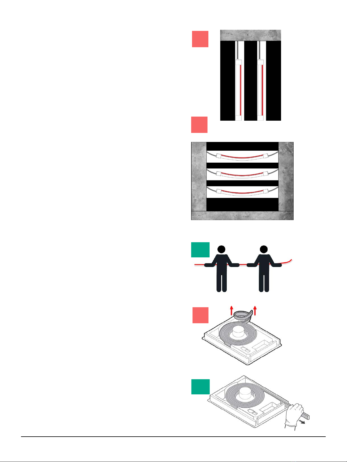
•Safe unboxing Molded Assemblies
Molded Assemblies ship in special boxes
with inserts designed for easy un-coiling.
These often have gloves included to help
keep smudges and fingerprints off the
illumination edge of FloppyFlex.
NEVER pull FloppyFlex out of the box from
the center or twist it backwards. Use the box
as intended. Thread the FloppyFlex end
through the box insert and pull gently to un-
coil.

FloppyFlex User Manual Version 2.0 - 22 August 2022 - 13 -
•Safe unboxing Unterminated Reels
Bulk unterminated FloppyFlex ordered in
large quantities arrives on reels of various
lengths depending on type.
Reels are shipped with a plastic axel which
installs through the center hole and allows
the reels to rotate in the shipping box.
Always make sure the reel with un-coil
overhand, so that the orientation of the
FloppyFlex is as horizontal as possible.
Additional hands are needed to support
FloppyFlex if unboxing and cutting long runs
over 2 meters. It is best to prop up the reel on
a platform which is level with a long table or
bench surface to support the length as
horizontally flat as possible.
NEVER pull FloppyFlex from a reel resting on
the ground sideways or any other angle
which may violate care and handling
instructions.
•Safe Coiling FloppyFlex Assemblies
Some projects may require test-fitting
FloppyFlex, or may only have rough length
measurements for installation and mounting
points
In these cases, we encourage specifying bulk
lengths of unterminated FloppyFlex and an
assortment of our our EZ Connect system
components for DIY termination in the shop
or onsite (see instructions below).
Completed FloppyFlex assemblies often
need to travel from shop to field or from one
location to another.
The best course of action for short-term
storage and transportation of completed
assemblies is to coil FloppyFlex relative to its
bending direction: Side-to-Side (STS) or
Front-to-Back (FTB).
Cutting and termination should take place on
a long, flat surface such as a workbench or
table. From this position, start from one end
and coil the FloppyFlex back onto itself,
forming a circle with diameter no smaller than
the minimum bending diameter of the type.
Continue coiling the FloppyFlex around itself
until a complete circle with multiple rings is
formed. At this point you may use Velcro ties
to secure and hold the assembly together.
Keep the assembly flat by layering cardboard
above and below. Several Coiled assemblies
can be stacked and transported in this
manner.

FloppyFlex User Manual Version 2.0 - 22 August 2022 - 14 -
Cut Mark
Ratcheting Cutter
Used to accurately cut FloppyFlex
at 90˚ angles
Grippers
Used to install some specialized
FloppyFlex connectors
(Not needed for EZ Connect)
Insertion Spreader
Used to
create insertion gap
behind PCB to input connector
prongs
CUTTING FLOPPYFLEX
MINI TOOL KIT
The FloppyFlex Mini Tool Kit is available with necessary tools for cutting and terminating FloppyFlex
assemblies. The Mini Tool Kit contains a ratcheting cutter, insertion spreader, and grippers. The larger of
the two spreaders are used for FloppyFlex Large, Small and Flat profile products, while the smaller spreader
is used for FloppyFlex Mini profile. We highly recommend using the Mini Tool Kit for optimal results and
reduced risk of damage to the product.
CUTTING MARKS
FloppyFlex contains an inner flexible PCB which is designed with segments of LEDs (sometimes referred to
as pixels) that are repeated throughout the length of the product. Each segment is identical and can fully
function as a standalone run of FloppyFlex. The length of each segment is specified as the Minimum Cut
Length and are indicated on the exterior body with a dotted line Cut Mark. These cut marks indicate safe
cutting locations which can be terminated as either input or output side of a FloppyFlex run.
Different styles of FloppyFlex can have varying
amounts of LEDs per segment which affects the
Minimum Cut Length. Please refer to the product’s
individual specification sheet for more information.

FloppyFlex User Manual Version 2.0 - 22 August 2022 - 15 -
Cutting Instructions
FloppyFlex Cutting Instructions are applicable to all types of STS and FTB FloppyFlex. Cutting FloppyFlex
is a quick and easy process with minimal tools and is adaptable for preparing FloppyFlex in the shop
beforehand or in the field. Visit https://tmb.com/floppyflex/ for a full instructional video demonstration.
•STEP 1 –Prepare for Cutting
Locating the desired cut mark on a length of
raw FloppyFlex. Prepare the cutters by
opening the jaws completely, so that the
cutting blade is fully extended.
Be sure to follow all care and handling
procedures for FloppyFlex to prevent
incorrect bending and twisting.
•STEP 2 –Alignment
Place the base of the Floppyflex towards the
back of the cutter jaws so that the illumination
side is the furthest away from the blade.
Line up the FloppyFlex cut mark with the
blade’s path to ensure a straight and safe cut.
If necessary, ratchet down the blade closer to
the FloppyFlex body by repeatedly squeezing
the handle. Be sure to stop the blade just
before cutting to determine proper alignment.
•STEP 3 –Begin Cutting
Once the FloppyFlex is aligned with the
blade, continue ratcheting down the blade to
begin cutting.
The ratcheting cutter is designed to make
cutting incremental. You will repeat handle
squeezing several times to complete the
cutting process
•STEP 4 –Inspection
Once the blade has cut through the entire
FloppyFlex Body, remove the newly cut
sections from the ratcheting cutter.
Inspect the cleanly cut edges. Make sure the
cuts are at exactly 90 degrees
(perpendicular) to the length of FloppyFlex
and there are no deformities in the edges or
PCB.

FloppyFlex User Manual Version 2.0 - 22 August 2022 - 16 -
EZ Connect End Entry Power Feed
EZ Connect End Cap
TERMINATING FLOPPYFLEX
SIDE NUMBERING SYSTEM
The FloppyFlex internal PCB is not symmetrically located within the housing, meaning each end will have a
different PCB placement and will only marry with the appropriate EZ-Connector. After cutting, inspect end
and note which numbered side is visible, “01” or “02”. The visible number determines which style of
connection must be used.
Note: Most single and variable color FloppyFlex options can be powered from either end, but
FloppyFlex Digital products only operate in one direction, with control signal input on side “01”.
EZ CONNECT SYSTEM
EZ Connect components are used to terminate a raw cutting of FloppyFlex. Connector pins are inserted into
side 01 or 02 and directly contact the copper leads of the inner PCB. The main connector is then sealed into
place with compression fittings and a silicone gasket, all housed in a durable cover. Correct installation will
result in a water-resistant, IP67 rated assembly.
EZ Connect power feeds link FloppyFlex to a
power supply or driving controller via cable. A wide
variety of EZ Connect configurations are available
with feed cables oriented in end, side, or bottom
entry for both side 01 and side 02.
EZ Connect End Caps terminate the end of a
FloppyFlex run and insulate it from surrounding
surfaces.
EZ Connect Jumpers connect two or more pieces
of FloppyFlex together (with respect to max run
lengths).

FloppyFlex User Manual Version 2.0 - 22 August 2022 - 17 -
Insertion Spreader
Placement
PVC
Strip
PCB
Correct placement – behind the PCB
Incorrect placement – in front of the PCB
INSERTING THE SPREADER
The inner components of FloppyFlex are hermetically sealed inside a PVC or silicone housing that offers
little clearance for connector installation. Using the insertion spreader tool, users can separate the flexible
PCB from the PVC insulating strip and create a “pocket” for the connector input. This allows easy access to
the copper conductors of the flexible PCB and ensures proper connectivity between the conductors and
connector pins.
Placement of the Insertion Spreader is important as is insertion depth. Pay close attention and understand
the cross-section of components before attempting to insert the spreader. If the spreader is incorrectly
seated in front of the PCB, there may be damage to the PCB components, which will make the first segment
inoperable. If damage does occur, and the first segment malfunctions, remove it with the cutter and continue
to the next segment.
FloppyFlex User Manual Version 2.0 - 22 August 2022 - 18 -
Side 01 EZ Connect Power Feed Components
Side 02 EZ Connect End Cap Components
Side 01 EZ Connect Power Feed Components
EZ CONNECT TERMINATION INSTRUCTIONS
FloppyFlex Termination instructions are applicable to all types of STS and FTB FloppyFlex and all variations
of EZ Connect Power Feeds, End Caps and Jumpers. Terminating FloppyFlex is a quick and easy process
with minimal tools and is adaptable for preparing FloppyFlex in the shop beforehand or in the field. Visit
tmb.com for full instructional videos.
Note:Custom FloppyFlex assemblies with molded connections are also available with factory lead time.
Contact sales@tmb.com for more information.
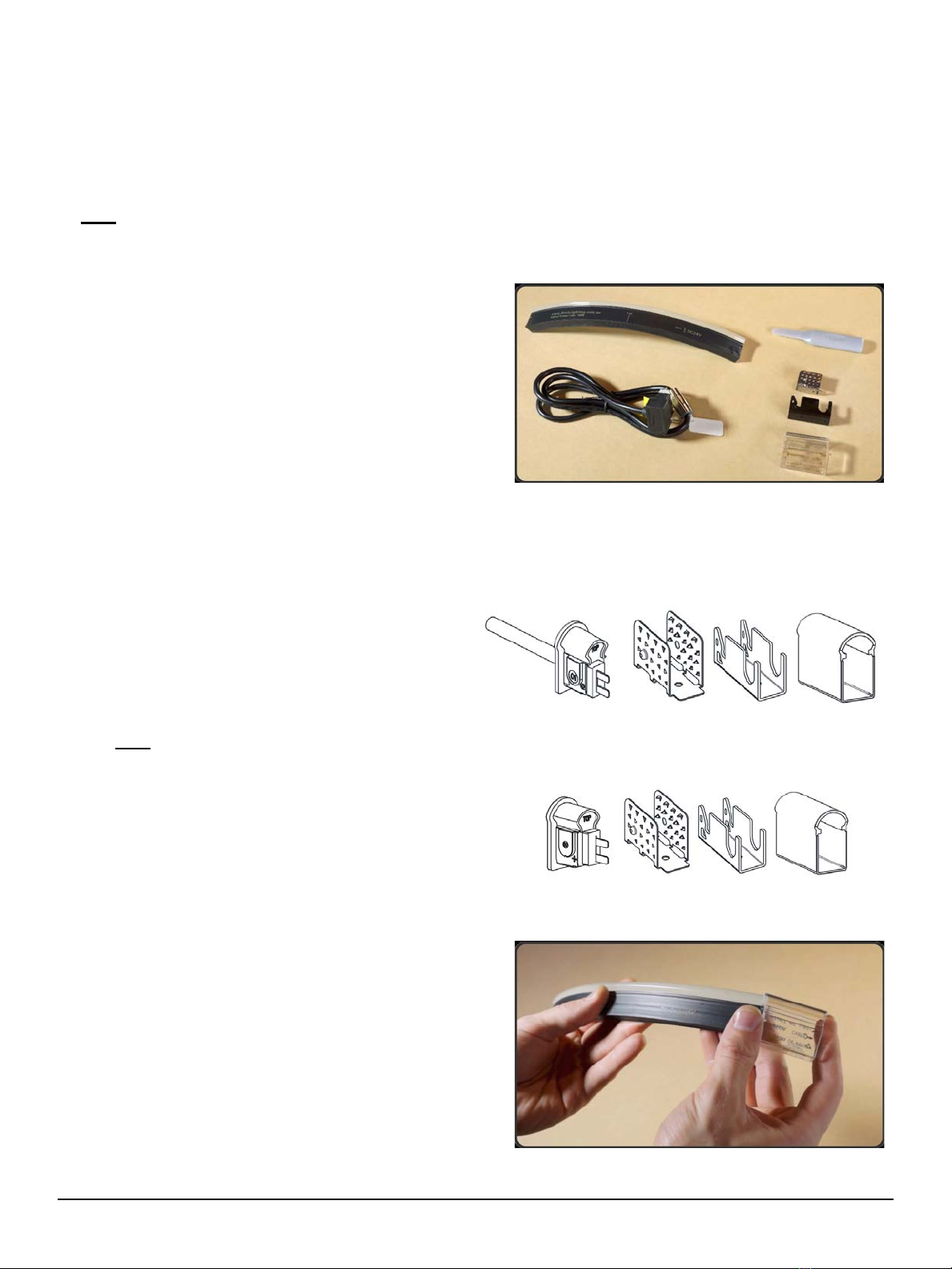
•STEP 1 - Gather Components
Most standard FloppyFlex assemblies will
need the following materials:
Raw FloppyFlex (cut to desired length)
Side 01 EZ Connect Power Feed
Side 02 EZ Connect End Cap
Insertion Spreader
Each EZ Connect option has a set of
common components, all of which are
necessary to install correctly to achieve IP67
rating:
Connector w/ silicone gasket
Compression Support Frame
Anti-Skidding plate
Plastic Snap Cover
Note: The Termination instruction example in
this User Manual is a standard side 01 EZ
Connect Power Feed with Large 270° Profile
STS.
Specialized FloppyFlex assemblies with EZ
Connect Jumpers or side 02 EZ Connect
Power Feeds follow the same instructions
and concepts for termination.
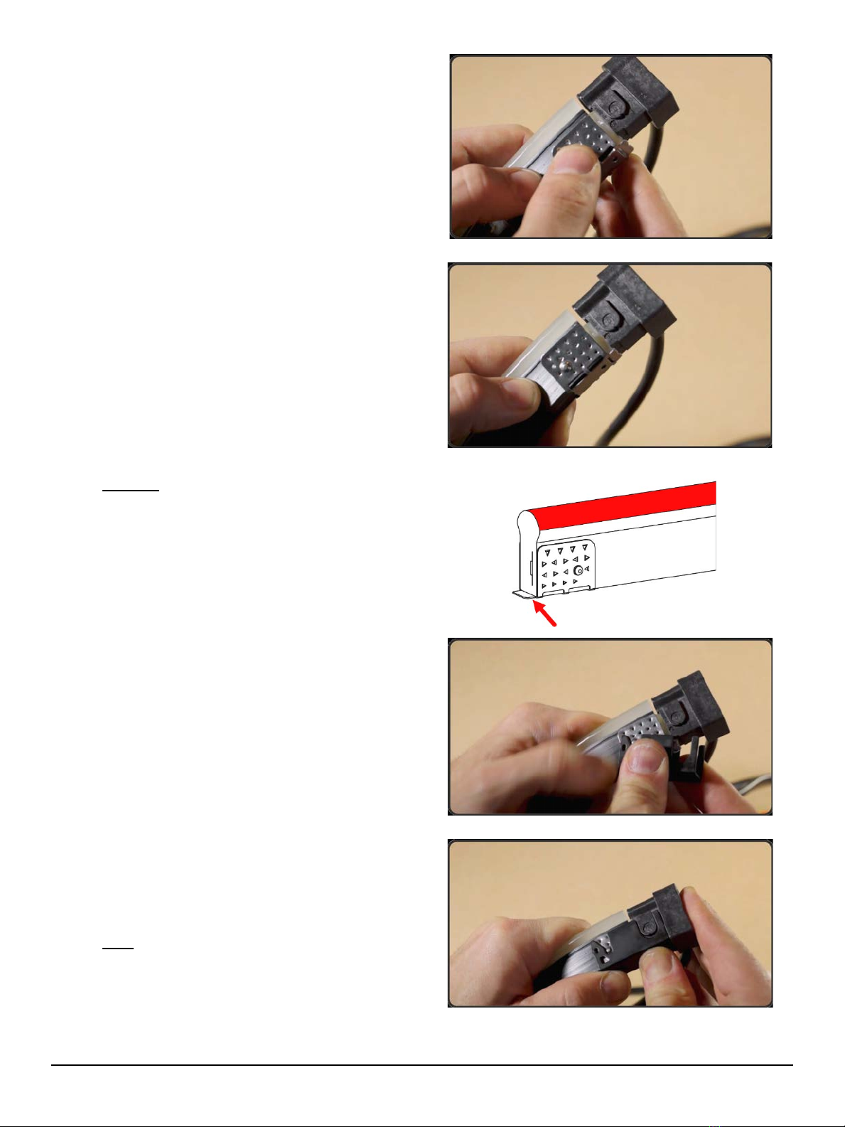
•STEP 2 –Prepare Plastic Snap Cover
Slide the plastic snap cover over the body of
the FloppyFlex and place it a few inches
away from the assembly end to leave room
for next steps.
When installing the snap cover, directionality
matters. Pay attention to the instruction
printed on the bottom of the piece.
The snapping end of the cover is indicated
with an arrow and should point towards the
assembly end.
FloppyFlex User Manual Version 2.0 - 22 August 2022 - 19 -
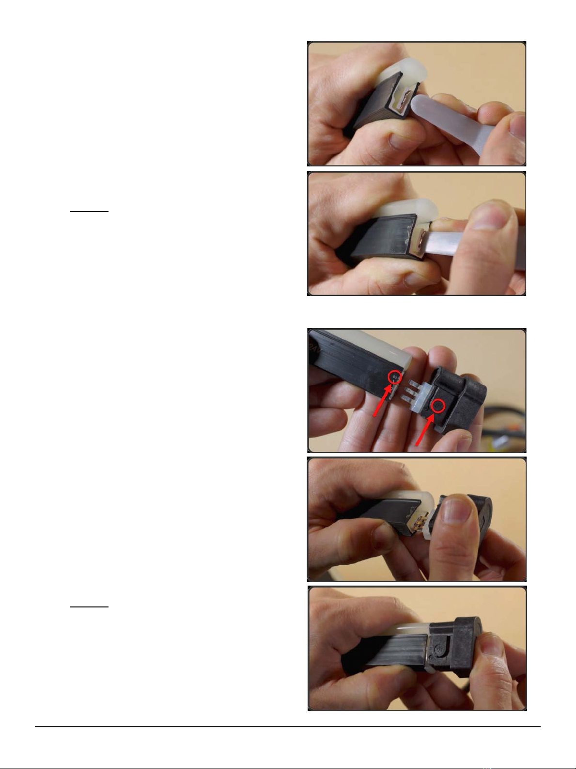
•STEP 3 –Insertion Spreader
Grab the assembly end and face it towards
you so that you can inspect the cross-section
of internal components.
Locate the flexible PCB and gently insert the
spreader behind the copper belt. If done
correctly, the insertion spreader should be in
the gap created between the PCB and the
PVC insulation strip.
Insert the spreader not more than 10 mm or
about ½ in and move up and down 3-5 times
to widen the cavity.
Warning: Proper insertion placement is
extremely important. Inserting the spreader
into the front side of the PCB may damage
LEDs and other components.
•STEP 4 –Install the Connector
Each connector is imprinted with 01 or 02
label on the body to help identify the style.
Each cut mark of FloppyFlex will indicate if
the assembly end is either side 01 or 02. Look
for this label on the edge of the assembly end
and match the number with the appropriate
connector style.
Once you have located the correct connector,
gently insert the pins of the connector into the
gap created by the insertion spreader.
Maintain a straight alignment and do not
force the connector into place.
The connector is correctly seated when the
silicone gasket is in contact and compressed
by the assembly end of the FloppyFlex.
When installing an EZ connect Power Feed,
The FloppyFlex assembly is now safe to
connect to power and/or drivers to test
connection. Make sure to disconnect power
before continuing to next steps.
Warning: Gentle pressure is all that should
be required to install connector. If you are
experiencing abnormal resistance, it is
possible that connector pins are splitting
around the PCB or may be installed
incorrectly on the front side of PCB.
If this occurs, simply remove the connector,
inspect for any damage, and repeat Step 3 to
reopen the cavity.
FloppyFlex User Manual Version 2.0 - 22 August 2022 - 20 -
•STEP 5 –Install Anti-Skidding Plate
The Anti-Skidding Plate is designed to grip
onto the FloppyFlex body and provide
leverage to install the Compression Support
Frame.
The wings of the metal Anti-Skidding plate
are intentionally flexible and are intended to
facilitate easier installation.
To install the plate, use fingers to unfold the
wings slightly wider than the width of the
FloppyFlex body. Then position the plate so
that the edge of the frame aligns exactly with
the clean edge of the FloppyFlex.
There is a slight lip on the bottom of the plate,
which should overlap the edge of the
FloppyFlex and align with the bottom of the
silicone connector gasket.
Once aligned, push the bottom of the plate
into place, making sure the plate hugs the
body as closely as possible. Use fingers to
squeeze the plate wings onto the FloppyFlex
until they successfully bite into the housing.
Warning: Improper alignment may result in
the IP67 rating being compromised. Water
ingress failure due to incorrect assembly is
not covered by warranty.
•STEP 6 –Install Compression Support
Frame
The Compression Support Frame is a strong
metal support designed to interface with
strength member points on the Anti-Skidding
Plate and connector to effectively lock the
connector onto the FloppyFlex end. It
ensures the completed assembly cannot
easily be removed.
Align the frame so that the “U” cutout faces
the connector side.
Slide the frame over both the connector and
Anti-Skidding Plate and apply even pressure
until the plate is flush along the bottom of the
plate and connector with no gaps around the
frame.
Note: The Compression Support Frame is
intended to fit tightly. Installing the Frame
correctly may sometimes require additional
force on the connector to push it towards
FloppyFlex end until the frame can snap into
place.
This manual suits for next models
1
Table of contents
Other TMB Lighting Equipment manuals


