manuals.online logo
Brands
  1. Home
  2. •
  3. Brands
  4. •
  5. NICOR
  6. •
  7. Lighting Equipment
  8. •
  9. NICOR EXL2 Series User manual

NICOR EXL2 Series User manual

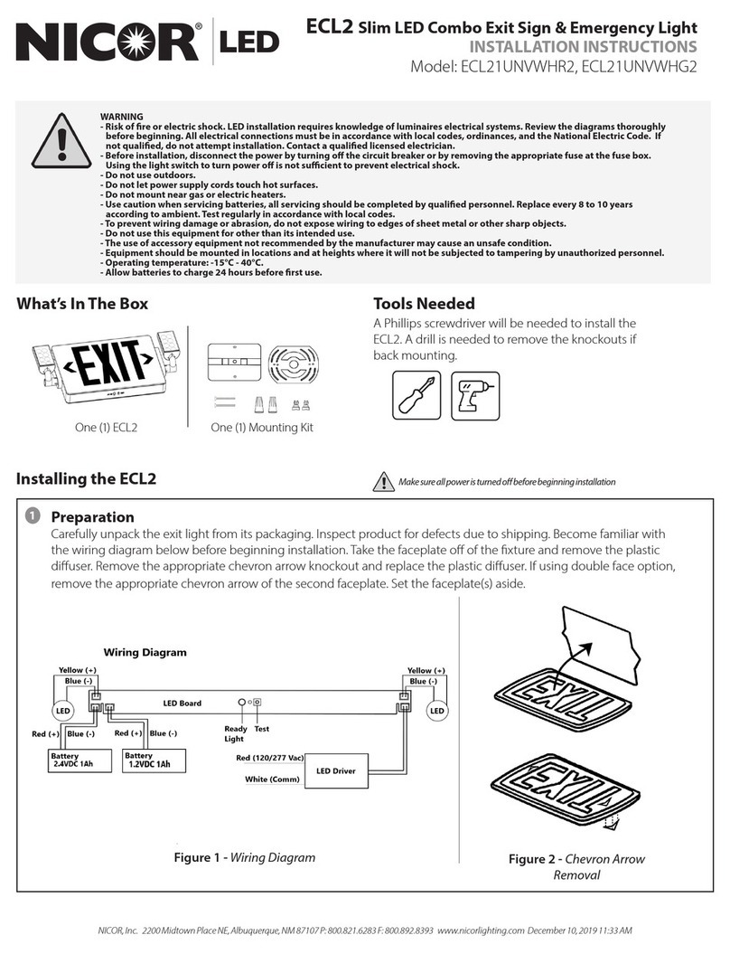
NICOR, Inc. 2200 Midtown Place NE, Albuquerque, NM 87107 P: 800.821.6283 F: 800.892.8393 www.nicorlighting.com July 21, 2021 2:19 PM
EXL2 SURFACE MOUNT EDGE-LIT LED
INSTALLATION INSTRUCTIONS
Model: EXL210UNVALCLG1SD, EXL210UNVALCLR1SD,
EXL210UNVALMRG2SD, EXL210UNVALMRR2SD
What’s In The Box
One (1) EXL2-SD One (1) Mounting Kit
Important Safeguards
READ AND FOLLOW ALL SAFETY INSTRUCTIONS
• All servicing should be performed by qualied personnel only
• All electrical service connections must be in accordance with local codes, ordinances, and the National Electric Code.
• Before starting this installation, disconnect the power by turning o the circuit breaker or by removing the appropriate fuse at the fuse box.
Using the light switch to turn power o is not sucient to prevent electrical shock.
• Do not use outdoors
• Do not let power supply cords touch hot surfaces
• Do not mount near gas or electric heaters
• Use caution when servicing batteries. Battery acid can cause burns to skin and eyes. If acid is spilled on skin or in eyes, ush with fresh water
and contact a physician immediately.
• Equipment should be mounted in locations and at heights where it will not be subject to tampering by unauthorized personnel.
• The use of accessory equipment not recommended by the manufacturer may cause an unsafe condition.
• Do not use this quipment for other than its intended use.
• Allow battery to charge for 24 hours before rst use.
SAVE THESE INSTRUCTIONS
Tools Needed
A Phillips screwdriver will be needed to
install the EXL2.
Make sure all power is turned o before beginning installation
Preparation
• Carefully unpack the exit sign from its packaging. Inspect
product for defects due to shipping.
• Set aside EXIT panel for later steps.
Mounting and Wiring
Wall and Ceiling Mount
•
Use screwdriver to open front cover and connect the battery to
the circuit board.
•
Remove the (2) small hole plugs from the back (for wall mount)
or top (for ceiling mount) and install them in the holes on the
end cap.
•
Remove the large hole plug (back or top as desired) and install
the cable bushing.
•
Attach the canopy to the xture in the desired location using
the included screws (M4x12).
•
Feed the wiring out of the xture, through the canopy and
crossbar and connect per the wiring diagram.
•
Attach the crossbar to the junction box with screws (#8-32)
•
Close front cover of xture.
•
Mount xture on crossbar using included screws (M4x40)
1
Installing the EXL2
2
Figure 1 - Wall Mount
Figure 2 - Top Mount
NICOR, Inc. 2200 Midtown Place NE, Albuquerque, NM 87107 P: 800.821.6283 F: 800.892.8393 www.nicorlighting.com July 21, 2021 2:19 PM
EXL2 SURFACE MOUNT EDGE-LIT LED
INSTALLATION INSTRUCTIONS
Model: EXL210UNVALCLG1SD, EXL210UNVALCLR1SD,
EXL210UNVALMRG2SD, EXL210UNVALMRR2SD
Figure 3 - Side Mount
Mounting and Wiring
Side Mount
•
Use screwdriver to open front cover and connect the battery to
the circuit board.
•
Remove the hole plug and install the canopy on the end with
screws (M4x12).
•
Feed the wiring out of the xture, through the canopy and
crossbar and connect per the wiring diagram.
•
Attach the crossbar to the junction box with screws (#8-32)
•
Close front cover of xture.
•
Mount xture on crossbar using included screws (M4x40)
Panel and Chevron Installation (for all mounting styles)
•
Peel protective lm from EXIT panel and gently insert panel into
main body assembly. If EXIT panel is for single face, make sure EXIT
lettering direction is correct.
•
Peel o unused chevron(s) from EXIT panel.
Operating status
When AC power is supplied to xture, the unit will automatically
initiate a self-test and self-diagnostic test as follows:
•
Veries battery disconnection & charger board failure every 5
seconds.
•
1 minute self-test every month.
•
30 minutes self-test every 6 months after installation.
•
90 minutes self-test every 12 months after installation.
Dual color LED lamp indicator shows the following status:
•
Green color steady on: Ready
•
Green color blinking Testing
•
Red color blinking Service Alert - see diagnostic chart
2
Figure 5 - Film Removal and
Panel Installation
Figure 4 - Wiring Diagram
3
Light Status Meaning
One blink ON/pause every 4 seconds Battery is not connected
Two blinks ON/pause every 4 seconds Battery voltage lower than acceptable value
Three blinks ON/pause every 4 seconds Charger board fault
Four blinks ON/pause every 4 seconds Transfer function failure
Seven blinks ON/pause every 4 seconds LED strip fault
NOTICE
After solving the fault of the exit sign, please press and hold the test button for 2 seconds to reset.
LED indicator will show green when fault is cleared.
NICOR, Inc. 2200 Midtown Place NE, Albuquerque, NM 87107 P: 800.821.6283 F: 800.892.8393 www.nicorlighting.com July 21, 2021 2:19 PM
EXL2 SURFACE MOUNT EDGE-LIT LED
INSTALLATION INSTRUCTIONS
Model: EXL210UNVALCLG1SD, EXL210UNVALCLR1SD,
EXL210UNVALMRG2SD, EXL210UNVALMRR2SD
GENERAL PRODUCT WARRANTY. Each NICOR product will be free from defect in materials and workmanship for a period of one (1) year from the date of delivery to the end-user. Powder Coat paint nish on products, other
than natural aluminum or brass, will not exhibit cracking, peeling, excessive fading, or corrosion during the warranty period. Exceptions apply as dened in each NICOR product’s specication sheets, which are incorporated
by reference herein. Warranty does not cover improper installation, operation, alterations, power surges, overheating due to external conditions, or acts of nature including but not limited to lightning strikes.
ALL NICOR WARRANTIES APPLY ONLY TO NICOR PRODUCTS THAT HAVE BEEN PURCHASED FROM AN AUTHORIZED NICOR DISTRIBUTOR; WHO PURCHASED THE PRODUCT DIRECTLY FROM NICOR; THE PRODUCT WAS NEW
AND IN AN UNOPENED NICOR PACKAGE AT THE TIME OF INSTALLATION; AND WAS INSTALLED BY A LICENSED ELECTRICIAN OR UNDER THE SUPERVISION OF A LICENSED ELECTRICIAN.
This device complies with part 15 of the FCC Rules. Operation is subject to the following two conditions: (1) This device may not cause harmful interference, and (2) this device must accept any interference received,
including interference that may cause undesired operation.
NOTE: This equipment has been tested and found to comply with the limits for a Class B digital device, pursuant to part 15 of the FCC Rules. These limits are designed to provide reasonable protection against harmful
interference in a residential installation. This equipment generates, uses and can radiate radio frequency energy and, if not installed and used in accordance with the instructions, may cause harmful interference to radio
communications. However, there is no guarantee that interference will not occur in a particular installation. If this equipment does cause harmful interference to radio or television reception, which can be determined by
turning the equipment o and on, the user is encouraged to try to correct the interference by one or more of the following measures:
—Reorient or relocate the receiving antenna.
—Increase the separation between the equipment and receiver.
—Connect the equipment into an outlet on a circuit dierent from that to which the receiver is connected.
—Consult the dealer or an experienced radio/TV technician for help
4For manual test, press test button as follows:
• Press test button once within 2 seconds 30 second test
• Press test button twice within 2 seconds 3 minutes test
• Press test button 3 times within 2 seconds 30 minutes test
• Press test button 4 times within 2 seconds 90 minutes test
NOTE
Battery Testing: Allow 24 hours of charging before testing.
• Push In TEST Button - LED display will switch to battery power and remain lit
• Release TEST Button - LED display will switch back to AC power

This manual suits for next models

4

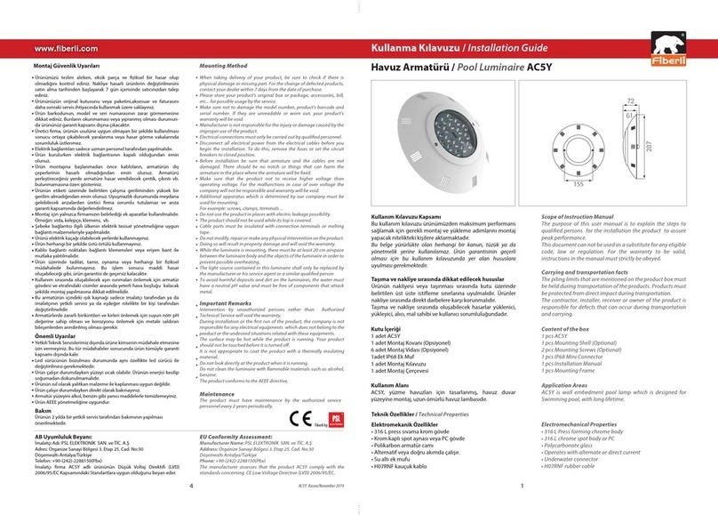
Other NICOR Lighting Equipment manuals

NICOR EMB250 -10-UNV User manual

NICOR

NICOR EMB250 -10-UNV User manual

NICOR ECL21UNVWHR2 User manual

NICOR

NICOR ECL21UNVWHR2 User manual

NICOR VT2 LED VAPORTITE User manual

NICOR

NICOR VT2 LED VAPORTITE User manual

NICOR LED ECL3 User manual

NICOR

NICOR LED ECL3 User manual

NICOR ECL5 Series User manual

NICOR

NICOR ECL5 Series User manual

NICOR EML6 User manual

NICOR

NICOR EML6 User manual

NICOR LED EMB4001UNV Series User manual

NICOR

NICOR LED EMB4001UNV Series User manual

NICOR EML7 User manual

NICOR

NICOR EML7 User manual

NICOR DCR56 Series User manual

NICOR

NICOR DCR56 Series User manual

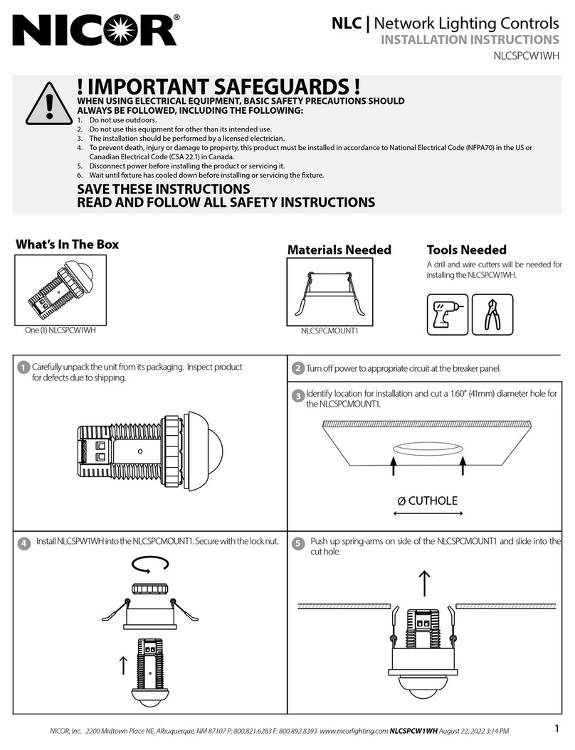
NICOR NLCSPCW1WH User manual

NICOR

NICOR NLCSPCW1WH User manual

NICOR TPE Series User manual

NICOR

NICOR TPE Series User manual

NICOR EXL6 User manual

NICOR

NICOR EXL6 User manual

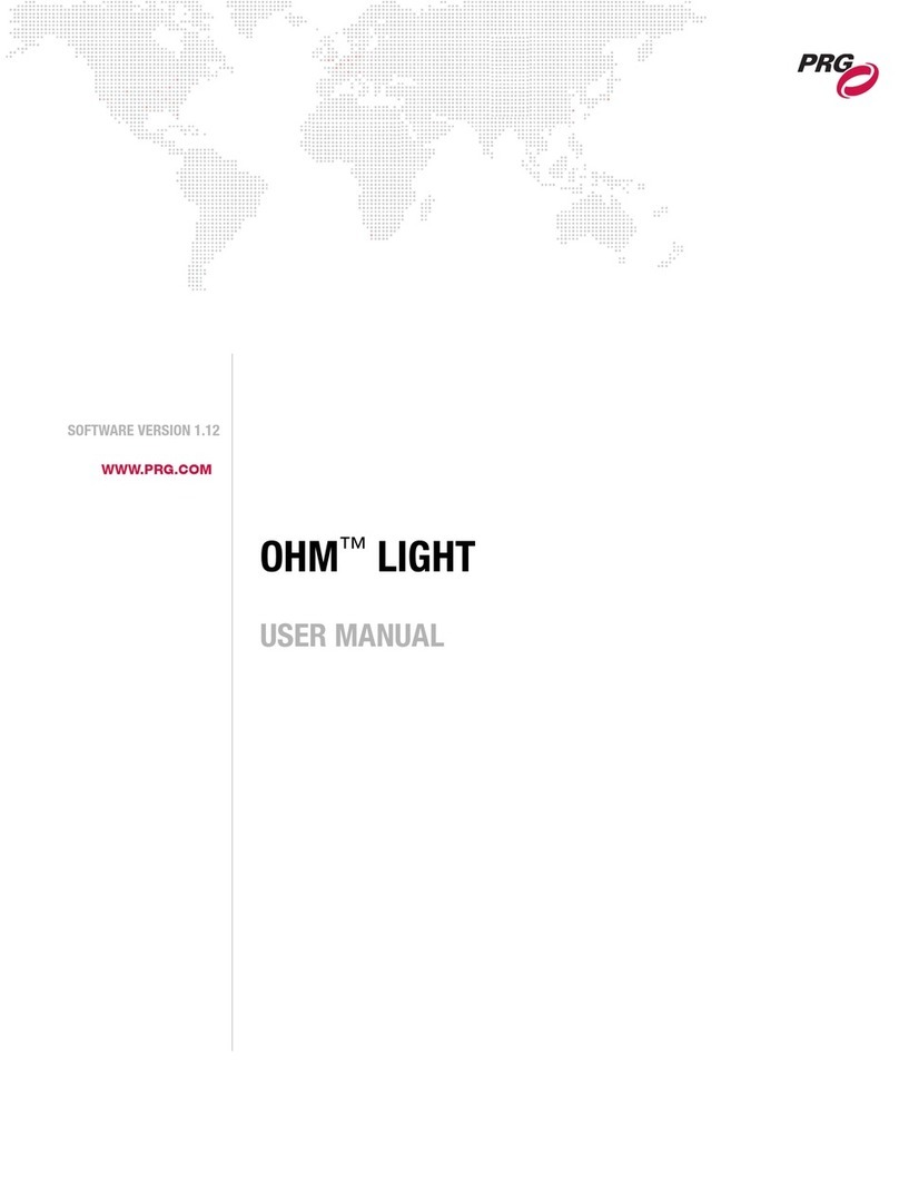
Popular Lighting Equipment manuals by other brands

Life 39.LED09390 quick start guide

Life

Life 39.LED09390 quick start guide

Ludwig Pani BP 1,2/HMI User handbook

Ludwig Pani

Ludwig Pani BP 1,2/HMI User handbook

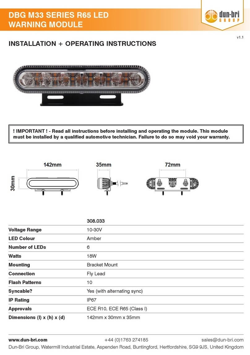
dun-bri GROUP DBG M33 Series Installation & operating instructions

dun-bri GROUP

dun-bri GROUP DBG M33 Series Installation & operating instructions

Pool Controls Ozone Chemigem user manual

Pool Controls

Pool Controls Ozone Chemigem user manual

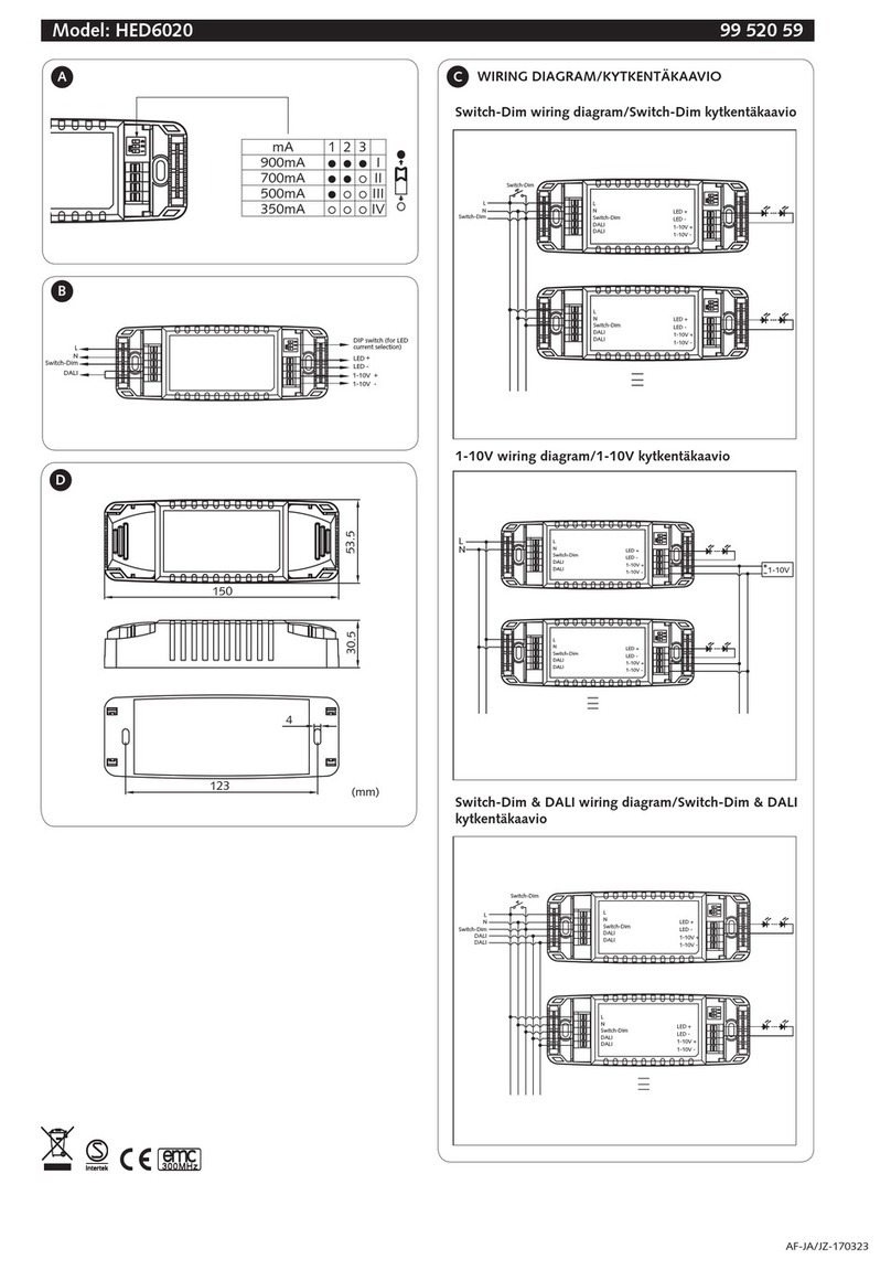
Malmbergs HED6020 instruction manual

Malmbergs

Malmbergs HED6020 instruction manual

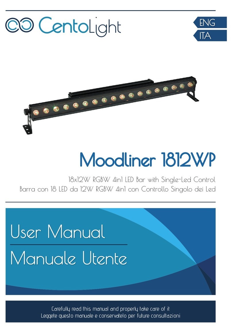
CentoLight Moodliner 1812WP user manual

CentoLight

CentoLight Moodliner 1812WP user manual

ETC Source Four LED Series user manual

ETC

ETC Source Four LED Series user manual

Menvier Beamlite installation instructions

Menvier

Menvier Beamlite installation instructions

RAB FIELD-ADJUSTABLE TOMO-2 instructions

RAB

RAB FIELD-ADJUSTABLE TOMO-2 instructions

Fiberli AC5Y installation guide

Fiberli

Fiberli AC5Y installation guide

Philips 300S Operation manual

Philips

Philips 300S Operation manual

PRG OHM LIGHT user manual

PRG

PRG OHM LIGHT user manual

Philips 56452-17-16 user manual

Philips

Philips 56452-17-16 user manual

KALE Hello light HL-ML6P60D user manual

KALE

KALE Hello light HL-ML6P60D user manual

Vision & Control LDLF60x480-IR850/24V Instructions for use

Vision & Control

Vision & Control LDLF60x480-IR850/24V Instructions for use

Eliminator Lighting EX-2 operating instructions

Eliminator Lighting

Eliminator Lighting EX-2 operating instructions

Kemo Electronic M079N quick start guide

Kemo Electronic

Kemo Electronic M079N quick start guide

EuroLite LED FE-60 IR Flower Effect user manual

EuroLite

EuroLite LED FE-60 IR Flower Effect user manual

manuals.online logo
manuals.online logoBrands
  • About & Mission
  • Contact us
  • Privacy Policy
  • Terms and Conditions

Copyright 2025 Manuals.Online. All Rights Reserved.