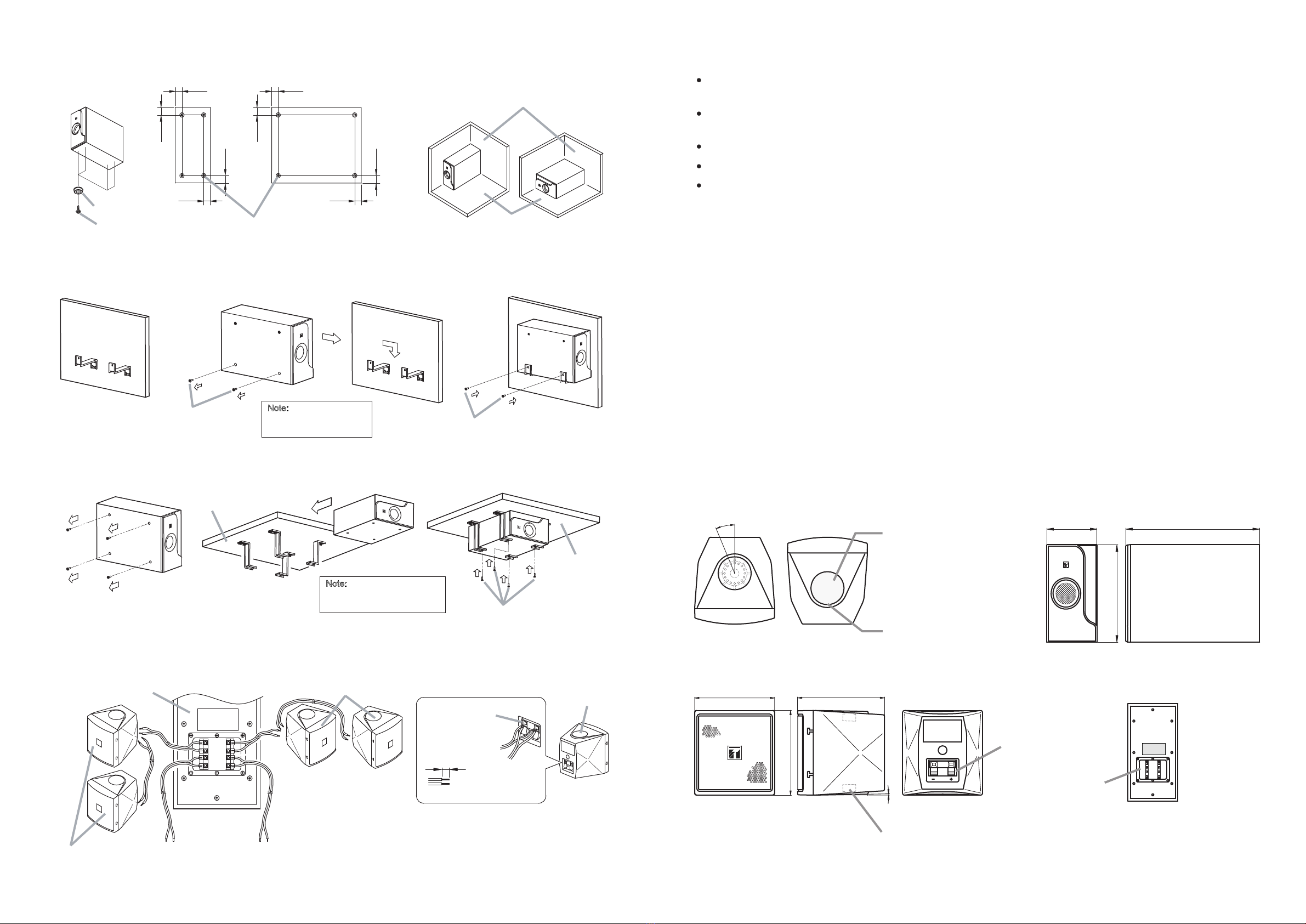
manuals.online logo
Brands
  1. Home
  2. •
  3. Brands
  4. •
  5. Toa
  6. •
  7. Speakers System
  8. •
  9. Toa BS-301B AS User manual

Toa BS-301B AS User manual

TOA Corporation
Traceability Information for Europe (EMC directive 2004/108/EC)
Manufacturer:
TOA Corporation
7-2-1, Minatojima Nakamachi, Chuo-ku, Kobe, Hyago,
Japan
Authorized representative:
TOA Electronics Europe GmbH
Suederstrasse 282, 20537 Hamburg,
Germany
URL: http://www.toa.jp/
533-06-207-2B
USER MANUAL
SPEAKER SYSTEM
BS-301B AS
BS-301W AS
Thank you for using our product.
Please follow carefully the instructions stated in the manual to ensure correct installation and to prevent
any damage for the long-lasting use of the speaker unit.
TOA Corporation
8. SPECIFICATION
8.3. SATELLITE SPEAKER
8.2. SUBWOOFER
The specification may change without notice for improvement
Impedance
Sensitivity
Frequency response
Speaker component
Connection
Speaker box
Front Cover
Speaker bracket Steel plate, black paint Steel plate, white paint
Dimensions
Weight
Speaker Bracket…………………………………...………1
Hexagonal bolts M5 x 12 (with ring and spring ring)…...2
Model
150 ~ 20,000 Hz (-20dB below SPL)
8cm (3") cone-type
Push-in terminals (2 terminal poles)
BS-301B AS BS-301W AS
40W
8
85dB (Pink noise 330 ~ 3,300 Hz / 1W, 1M)
Feature
Accessories
92 (width) x 97.5 (height) x 100 (depth) mm
600g (without bracket)
HIPS Resin (Black) HIPS Resin (White)
Continuous Program Input
Impedance
Sensitivity
Frequency Response
Speaker component
Connection
Speaker cabinet Particle board with vinyl, black Particle board with vinyl, white
Front Cover ABS Resin (Black) ABS Resin (White)
Speaker bracket Steel plate, black paint Steel plate, white paint
Dimensions
Weight
Rubber foot…………………………..4
Speaker Mounting Bracket…………4
Taping screws 3 x 14.…….…...……4
Accessories
Feature
210 (width) x 390 (height) x 563 (depth) mm
11,500g (without bracket)
BS-301B AS BS-301W AS
120W per Channel
85dB (1W, 1M) (L or R Channel)
40 ~ 190 Hz (-10dB below SPL) ( L or R Channel)
16cm (6") 2-Speaker
Push-in terminals (8 connected terminal poles)
Model
7
6
1. SAFETY PRECAUTIONS
Read carefully the manual before installing or using the speaker unit
Please understand thoroughly the safety instructions and other important notes pertaining to safety stated in the
manual.
Keep the manual for future reference after you have finished reading.
Installation of speaker unit on bracket
Hindari memasang speaker di dalam ruangan yang
tidak berventilasi dengan baik. Bracket akan mudah
karat pada lokasi tersebut, yang pada akhirnya
dapat membuat speaker jatuh dan menyebabkan
kecelakaan pada seseorang.
During Installation of Speaker Unit
Indicates a potentially hazardous situation which, if mishandled, could
result in death or serious personal injury.
Indicates a potentially hazardous situation which, if mishandled, could
result in moderate or minor personal injury, and/or property damage.
WARNING
CAUTION
2
※
WARNING
CAUTION
Install the unit on a location which is secure enough
to support the speaker unit and mounting brackets.
Failure to do so may cause the speaker unit to fall
and inflict injury to people / damage the equipment.
Do not apply other methods to mount the bracket
other than the method stated in the manual. Speaker
unit may fall and cause injury to people.
Use the proper screws in accordance with the com-
position and structure of the ceiling or wall. Failure to
do so may cause the speaker to fall and inflict injury
to people.
Tighten the screws properly. Ensure the bolt is tight-
ened securely after the speaker unit is installed to
prevent it from falling and inflicting injury to people.
Do not install on an unstable location which may
cause the speaker unit to fall due to the strong or
continuous vibration.
The speaker is designed for indoor use, do not install
outdoors. Failure to do so may cause damage on the
speaker unit and or cause it to fall which may inflict
injury to people. Speaker is also prone to rain which
may cause short-circuit.
Do not install the speaker in a room without proper
ventilation. Bracket will get rusty easily which may
cause the speaker to fall and inflict injury to people.
Do not use anti-corrosion liquid. Anti-corrosion on
plastic (resin) or rubber may cause damage on the
speaker unit. The speaker unit may fall and inflict
injury on people
Be
When unpacking or storage the unit, be sure to handle
it with two or more persons. Falling or dropping the
unit may cause personal injury.
Owning to the subwoofer's size weight, be sure that
at least two persons are available to install it. Failure
to do so could result in personal injury.
careful of the sharp edges of the unit which may
cause injury.
To prevent short-circuit, ensure the amplifier is
always in the OFF condition when connecting it to
the speaker unit.
When Speaker Unit is in use
Do not place any heavy item on the speaker
because it may cause the speaker to fall which may
cause injury to people or damage on the equipment.
The heavy item may also fall and endanger safety.
Do not operate the speaker for long duration of time
with distorted sound. This indicates false operation
and it may introduce heat which subsequently may
cause fire.
Do not sit, stand on or dangle from the speaker unit
because it may cause the speaker to fall and inflict
injury to people as well as damage the equipment.
Do regular check of the equipment for early detec-
tion of any damage on the speaker unit or corrosion
on the mounting bracket. Failure to do so may cause
the speaker unit to fall and inflict injury to people.
8.1. SPEAKER SYSTEM
Total input power
Rated Impedance
Sensitivity / SPL
Frequency response
Speaker feature
Mounting
Model
40 ~ 20,000 Hz (L or R ch. Subwoofer + 2 satellite)
Subwoofer .......................1pc (Look at point 8.2)
Satellite speaker ..............4pc (Look at point 8.3)
Floorstanding / on-wall / on ceiling
BS-301B AS BS-301W AS
240W (2-Way)
6
83dB (Pink noise 330 ~ 3,300 Hz, 1W, 1M) L ch or R ch. only + 2 satellite
Input Connector
Push-in terminals
Total Weight
13.9 kg (without bracket)
7. THE SPEAKER CABEL CONNECTIONS
50
40 50
50
50
40 50
50
6
Note:
Screws to mount the
bracket are not available
2. GENERAL DESCRIPTION
3. DESCRIPTION ON OVERLOAD PROTECTION
4. DIMENSIONAL DIAGRAM
4.1. SATELLITE SPEAKER
4.2. SUBWOOFER
2-M5 Screw holes (top and bottom)
(Screw length max. 12mm or 0.47inch)
92 100
1°
97.5
22.5°
[Top] [ Bottom]
[Rear] [Rear]
Fixing seal
Note:
Find a big gap to open fixing seal.
Don't entering screwdriver too depth
(use its point)
Input Terminal
210 563
390
[Front] [Side]
[Front] [Side]
Input/Output
Terminal
Size : mm
3
Note:
Screws to mount the bracket
on ceiling are not available
RIGHT LEFT
LEFTRIGHT
INPUT
OUTPUT
Speaker unit
Speaker unit
Subwoofer unit
To Amplifier
To Subwoofer
To Amplifier
Input Terminal Speaker Speaker unit
[Rear]
Input Terminal
(Peeled cable)
9mm
To Speaker
The speaker system model BS-301 series is a speaker high-power with 2-way system that suitable for indoor
use only.
The wide range of frequency as well as capability of generating high sound pressure level make it an efficient
speaker to be used in a spacious room.
It is consisted of a subwoofer and four pieces satellite speakers.
he provided brackets allow the speaker to be mounted on various locations and direction radiations.T
The mounting brackets come together with the product as accessories.
The speaker unit is equipped with an overload protector. The system shall protect the speaker unit from overload
input which exceeds the allowed capacity.
Speaker’s volume will turn lower if the input to the speaker exceeds the maximum capacity of the speaker.
In such event, please turn down the amplifier volume to the minimum level and wait for 10 seconds. The system
shall automatically reset to normal condition. You may then gradually re-adjust the amplifier volume to the level
lower then the previous volume.
Important Note!
The system does not entirely protect against overload. Prolonged overload input to the speaker unit will cause
the system to malfunction. As such, the overload input will flow in and damage the speaker unit.
It is important to prevent prolonged overload input exceeding the maximum limit from flowing into the speaker
unit.
Screw hole is enclosed by the
fixing seal from the factory.
Before mounting the bracket,
fi xi ng s ea l shall be removed
first.
Ple ase u se a sma ll fl ath ead
screwdriver.
6.2.1. Installation on Floor
6.2.2. Installation on Wall
6.2.3. Installation on Ceiling
Use the rubber foot to install the subwoofer on the floor. Ensure the floor is even and flat so the subwoofer will
not move. Install the rubber foot on the side facing the floor.
For wall installation, unscrew two screws on the subwoofer. Take note of distance between the two screw holes
to be mounted on the wall (see image 4.3.2.)
For ceiling installation, please unscrew all screws (4 pieces) on the subwoofer. Take note of the distance
between the two screw holes to be mounted on the ceiling (see image 4.3.2.)
4-Rubber foot
Rubber foot Floor
Wall angle
Vertical position Horizontal position
4-Taping screws 3x14
Mount the bracket
on the wall
Unscrew 4 screws from
Subwoofer Place the screws back
onto Subwoofer
Ceiling
Ceiling
Unscrew 2 screws
from subwoofer Place the screws back
onto Subwoofer
(Turn)
4.3. BRACKET (TO MOUNT SPEAKER)
4.3.1. BRACKET FOR SATELLITE SPEAKER 4.3.2. BRACKET FOR SUBWOOFER
5. SPEAKER CABLE CONNECTIONS
5.1. SATELLITE SPEAKER
5.2. SUBWOOFER
6. INSTALLATION
6.1. SATELLITE SPEAKER
[Rear] [Rear]
9mm
[0.35inch]
9mm
[0.35inch]
(Length of peeled cable) (Length of peeled cable)
42
68
[Bottom] [Top]
[Side] Bracket-B
Bracket-A
Tightening Screw
55
155
222
[Side]
45
45
30360
30
16-Ø9
387
30 360 30
45
8-Ø9
[Distance of the screw
holes on wall]
[Distance of the screw
holes on ceiling]
[Distance of the screw
holes on wall or ceiling]
32
3-Ø4.5
20
4
6.1.2.1 Installation on Wall
[single-system installation sample]
[double-system installation sample]
6.1.2.2 Installation on Ceiling
6.2. SUBWOOFER
Speaker unit
Speaker unit
5
0o
(Horizontal) 90o
90o
(Turn to left)
90o
(Turn to right)
(Top View)
(Side View)
0o
(Vertical)
0o
(Vertical)
M5x12 Screw
M5x12 Screw
M5x12 Screw
Speaker unit
Bracket
Bracket
Bracket
Note:
Red : + (positive)
Black : - (negative)
Mount bracket
to the wall
Mount bracket
to the wall
Mount bracket to
the ceiling
Mount bracket to
the ceiling
Ceiling
Ceiling
Note:
Screws to mount
the bracket onto the
wall are not provided
Note:
Screws to mount the bracket
onto the ceiling are not provided
Loosen the tightening screw (right and left) to install
the bracket to the speaker unit. Take note of
Bracket-A; this is the part of the bracket which will be
attached to the wall or ceiling when installing the
speaker unit.
Place the speaker unit on an even and flat surface.
If the speaker unit is placed on glass or slippery surface, you may want to cover the surface with a cloth to prevent
the speaker from moving.
Before installing the bracket to speaker unit, remove / open the fixing seal enclosing the screw holes. Use a small
flathead screwdriver. Place the flathead screwdriver into the fixing seal slot (see image 4.1.). For installation of
single system, please remove only one fixing seal and for double system, please remove two fixing seals (top and
below) on one of the speaker units.
6.1.1. Speaker Unit installation without bracket
6.1.2. Speaker Unit installation with bracket
[Front]
[single-system installation sample] [double-system installation sample]
M5x12 Screw
M5x12 Screw
Size : mm
The sound generated by the subwoofer may differ, depending upon the mounting position. The Subwoofer instal-
lation samples illustrated here are some of the appropriate positions for room installation. It is recommended to
place the subwoofer at the corner of the room for better sound (especially bass).

This manual suits for next models

1

Other Toa Speakers System manuals

Toa HS-212 User manual

Toa

Toa HS-212 User manual

Toa SR-F09 User manual

Toa

Toa SR-F09 User manual

Toa SM-25M User manual

Toa

Toa SM-25M User manual

Toa F-505WP User manual

Toa

Toa F-505WP User manual

Toa ES-0422 User manual

Toa

Toa ES-0422 User manual

Toa F-505W User manual

Toa

Toa F-505W User manual

Toa CS-64 User manual

Toa

Toa CS-64 User manual

Toa F-2322C2 User manual

Toa

Toa F-2322C2 User manual

Toa SL-60W User manual

Toa

Toa SL-60W User manual

Toa 22-ME-AV User manual

Toa

Toa 22-ME-AV User manual

Toa 300-SD User manual

Toa

Toa 300-SD User manual

Toa SM-25A User manual

Toa

Toa SM-25A User manual

Toa CS-760B-AS User manual

Toa

Toa CS-760B-AS User manual

Toa F-1000B User manual

Toa

Toa F-1000B User manual

Toa SR-F05 User manual

Toa

Toa SR-F05 User manual

Toa HX-5 User manual

Toa

Toa HX-5 User manual

Toa PS-16BM User manual

Toa

Toa PS-16BM User manual

Toa F-2000BT User manual

Toa

Toa F-2000BT User manual

Toa F-121C/M User manual

Toa

Toa F-121C/M User manual

Toa F-2000W User manual

Toa

Toa F-2000W User manual

Toa SL-122 User manual

Toa

Toa SL-122 User manual

Toa SR-F08 User manual

Toa

Toa SR-F08 User manual

Toa F-122CU2 User manual

Toa

Toa F-122CU2 User manual

Toa F-2000BT User manual

Toa

Toa F-2000BT User manual

Popular Speakers System manuals by other brands

Magnavox MHT983 user manual

Magnavox

Magnavox MHT983 user manual

Electro-Voice FRi+ 122/94 Technical specifications

Electro-Voice

Electro-Voice FRi+ 122/94 Technical specifications

Sony SRS-Z510 Service manual

Sony

Sony SRS-Z510 Service manual

JBL Paragon owner's manual

JBL

JBL Paragon owner's manual

Sony SRS-NWZ10 operating instructions

Sony

Sony SRS-NWZ10 operating instructions

LG SPD7Y Simple manual

LG

LG SPD7Y Simple manual

Bazooka BPB24 installation instructions

Bazooka

Bazooka BPB24 installation instructions

Yamaha NS-125FPN owner's manual

Yamaha

Yamaha NS-125FPN owner's manual

Infinity Primus Theater Pack II Primus Series owner's guide

Infinity

Infinity Primus Theater Pack II Primus Series owner's guide

BRG Precision Products CBS6060 quick start guide

BRG Precision Products

BRG Precision Products CBS6060 quick start guide

Kanto Yumi user manual

Kanto

Kanto Yumi user manual

Electro-Voice FM12-2 datasheet

Electro-Voice

Electro-Voice FM12-2 datasheet

LG SN5Y Simple manual

LG

LG SN5Y Simple manual

Somogyi SAL PAB25A instruction manual

Somogyi

Somogyi SAL PAB25A instruction manual

Craig CHT973 owner's manual

Craig

Craig CHT973 owner's manual

AEG SRP 4343 iP instruction manual

AEG

AEG SRP 4343 iP instruction manual

Phoenix Gold RSd6.5cs owner's manual

Phoenix Gold

Phoenix Gold RSd6.5cs owner's manual

Samsung HW-FM45C user manual

Samsung

Samsung HW-FM45C user manual

manuals.online logo
manuals.online logoBrands
  • About & Mission
  • Contact us
  • Privacy Policy
  • Terms and Conditions

Copyright 2025 Manuals.Online. All Rights Reserved.