1. NOMENCLATURE AND FUNCTIONS
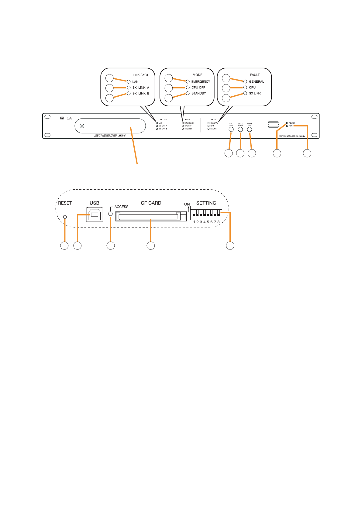
[Front]
1. LAN Indicator [LAN] (Green)
Lights when the LAN connector on the rear panel
is connected, and flashes during LAN
communications.
2. SX Link A Indicator [SX LINK A] (Green)
Lights when the SX Link A connector on the rear
panel is connected, and flashes while
communications are being performed via the SX
Link Connector A.
3. SX Link B Indicator [SX LINK B] (Green)
Lights when the SX Link B connector on the rear
panel is connected, and flashes while
communications are being performed via the SX
Link Connector B.
4. Emergency Indicator [EMERGENCY] (Red)
Lights when the CPU turns off (p. 5-7), and
flashes when a 24 V emergency cutoff* state
occurs involving any SX-2000AO within the
system.
* In the SX-2000 system, a 24 V emergency cutoff
input terminal that allows control of an
emergency audio input is provided on the SX-
2000AO's rear panel. When the SX-2000 system
is combined with an emergency broadcast
system, a 24 V DC is normally kept being
supplied to this emergency cutoff input terminal
and is cut off (24 V emergency cutoff function) in
emergency situations. This interrupts the
general-purpose broadcast from the SX-2000,
allowing the emergency broadcast system to
override it. (For details, see the separate
Installation Manual.)
5. CPU OFF Indicator [CPU OFF] (Red)
Lights when the CPU turns off (p. 5-7).
6. Standby Indicator [STANDBY]
This indicator is not used.
7. General Indicator [GENERAL] (Yellow)
Lights when the CPU turns off (p. 5-7) or when a
failure is detected in the SX-2000SM. Flashes
when a failure is detected in the system.
8. CPU Indicator [CPU] (Yellow)
Lights when the CPU turns off (p. 5-7) or when a
failure is detected in the SX-2000SM.
9. SX Link Indicator [SX LINK] (Yellow)
Flashes when cables are not connected to the
rear panel-mounted SX Link Connectors A and
B.
10. Fault Ack Key [FAULT ACK]
Stops the buzzer from sounding when failures
are detected in the SX-2000SM.