Metrix Audio UTV 1 User manual

Metrix Audio and Hogtunes Inc. are Owned by Powersports Audio Inc., Barrie, Ontario, Canada
All Products Designed and Engineered In Canada
UTV 1
Installation Manual
Part # UTV 1 Manual (Rev A)
Please take a few minutes and read this manual BEFORE starting
the installation! This manual is not “vehicle specific”, so reading
before starting will help you choose good mounting locations,
and help plan your wiring.
Any audio system can be a distraction to the driver
and/or passenger. Please use caution when
playing your stereo, especially in traffic.

Congratulations and thank you for your purchase of the Metrix Audio UTV 1 kit! Since
positive word of mouth is the best way to grow our business, we want your new
system to work as well as it was designed to. If you have any questions or concerns,
business hours (EST) at (705)-719-6361. If you still need help, then please consider a
professional installation by your retail dealer.
Important Notes Before Starting:
The BT-1 Bluetooth® receiver/controller has no audio transmitter functions. It is a
receiver only and will not allow you to make phone calls or send music to headsets.
The supplied “Element X” is a 2 channel amplifier rated at 75 watts per channel at 4
ohms. It comes equipped with 2 pairs of stereo output plugs (1 pair of left and right
“Mains”, and 1 pair of left and right “EXT’s”) allowing a total of 4 (2 pairs) 4 ohm
speakers to be powered by the single amplifier. As this kit comes, the amp will power
one set of speakers, but adding a second set of Element 1 speakers (4405-0505) can be
done easily at anytime without requiring the purchase of an additional amplifier.
The supplied Element 1 speakers were designed so they could be installed on the roll
cage down tubes in FRONT of the driver and passenger. From an audio perspective,
this is the preferred placement. The speakers can also be mounted behind the driver/
passenger. The speakers were constructed specifically for the Powersports world and
can withstand the elements. Normal rain or going through puddles etc is perfectly OK.
Normal washing is also OK, but damage to the speaker, or speaker failure caused from
pressure washing will NOT be covered by warranty.
Getting Started:
Locate the BT-1 Bluetooth® receiver/controller. It is a “snap in” piece that will fit the
common switch (21mm x37mm) “blank” found on most UTV dash boards. If your
machine does not have an empty “blank” or you want to do something custom, please
see the cutting dims on page 9. Once you choose an opening where you would like to
install BT-1, please have a good look to make sure there will be room behind the
opening for wires and the balance of the unit to snap in easily.
BT-1 Wire Color Codes
Taking your time and making secure wire connections is never a bad idea!
Black: The black wire must be connected to a good chassis ground (B-)
Red and Yellow : In this install, these 2 wires are to be joined together. See the 2
options below and select the one that works best for you. Once you decide, it’s a good
idea to refer to your vehicles manual for a suitable B+ power source.
A) If you want the unit to turn on/off only when your vehicles key is in the on
position, the yellow wire should be connected to a switched +12v power source.
B) If you want to be able to turn this unit on/off regardless if your vehicles key is on
or off, the yellow wire should be connected to a constant +12v power source.
2 11
Warranty Information:
Metrix Audio’s UTV 1 kit is warranted for a period of 24 months from the
original purchase date. The warranty applies to the original (retail) owner of
the system only. Proof of purchase is required for all warranty claims. Please
visit the warranty section of our website and fill out the form, or email or
phone us. Products found to be defective during the warranty period will be
repaired or replaced (with a product deemed to be equivalent) at Metrix
Audio’s sole discretion.
USA Tel: (608) 554-7631
Canada Tel: (705)-719-6361.
Email: info@metrixaudio.com
Website: www.metrixaudio.com
What Is Not Covered:
1) Any expense related to the removal or re-installation of this system.
2) Warranty to products with missing or defaced serial numbers.
3) Damage due to improper wiring.
4) Repairs of any kind performed by anyone other than Metrix Audio.
5) Subsequent damage to any other components.
6) Any product purchased from a non-authorized Metrix Audio dealer.
7) Damage from an accident or collision.
8) Damage from any custom mounting.
9) Damage to amp from obvious submersion in water or any other liquid.
10) Damage to speakers from “pressure washing”.
11) Speakers arriving to us with holes of any kind (or size) in cones.
12) Goods arriving to us damaged from improper shipping.
Metrix Audio is owned by PowerSports Audio Inc

Blue: The Blue wire on the BT-1 will be connected to the blue wire on the Element X
amplifier later on in the installation. The blue wire on BT-1 is the “remote turn on lead”.
When BT-1 is turned on, the blue wire “tells” the Element X amplifier to turn on.
Male 3.5mm: This is the BT-1 audio output and will plug into the Element X amplifiers
low level input later on in the installation. This cable is 2 meters long (6.6’) and should
be long enough in most installations to get to the amplifier. Please consider this when
choosing your amplifier location in the next section of the manual.
Female 3.5mm (Red): This “Aux In” connector allows you to send music to BT-1 from a
standard 3.5mm headphone jack on portable audio devices such as GPS or Sat Radio.
Pairing the BT-1 and operating instructions can be found on page 6.
Element X Amplifier Installation:
Mounting Location Considerations:
Like all amplifiers, Element X will generate heat. When choosing a mounting location,
please make sure the amp has adequate air flow. This amplifier is “smart” in that, if it
gets hot enough where it thinks damage to itself will occur, it will shut itself off
(go into protection) until its cool enough to safely operate again. Mounting the
amplifier next to a motors exhaust system or near radiators may cause the amplifier
to prematurely go into protection due to high ambient air temperatures. Please
consider this carefully when choosing your amplifiers mounting location. Also, as
major fans of playing with Powersports toys as we are, we understand that this
amplifier may be subject to getting wet or very dirty. If you think you may ever be in a
high water situation, you may want to mount the amp higher up off the floor if
possible. While every attempt has been made to prevent water from getting inside
your amp, it is not waterproof, and cannot be submerged without risking
non-warranty damage. In all cases, the amp must be mounted “inside” the vehicle, and
must NOT be subject to impeding any moving parts of the vehicle including
(but certainly not limited to) suspension etc.
The amplifiers mounting flanges have holes for screws or fasteners for securing the
amp, as well as “rectangles” in case you need to use “zip ties”. IN ALL CASES, screws
or fasteners is the suggested and preferred method to attach the amplifier to the
vehicle! Please take extra care to make sure the amplifier does not come loose while
operating your vehicle!
Wiring the amplifier:
Input: With the amplifier securely mounted, take the long male 3.5mm audio out
connector from the BT-1 and plug it into the female 3.5mm low level in on the amp.
You will see a 75mm (3”) piece of black heatshrink in the BT-1 box that can be used to
“secure” these two connectors together. Note: We suggest not using the heatshrink
until you have the system full installed and tested!
Output: In the box the Element X amp came in, you will see two 12’ long (3.6m)
speaker wires. The weather proof connectors on each end will plug into the amps
weatherproof connectors. Plug one of these into the right output on the amp (blue/
black wires) and the other into the left output on the amp (brown/black wires).
3
Element X Amp Quick Reference Wiring Chart
(When Used In UTV 1 Kit)
A = 3 Pin Power Harness Connector
B = Positive Wire (RED) with 20A Fuse
C = Ground Wire (Black)
D = Remote Turn On Lead (Blue)
E = Hi Level Input (Not Used)
F = Low Level Input (From BT-1)
G = Left EXT Output
H = Left Main Output
I = Right EXT Output
J = Right Main Output
10

Getting Power to your amp:
Plug the long harness with red, black, and blue wires into the mating 3 pin connector
on the amp.
Ground: The black ground wire must be properly connected to a good chassis ground.
Poor ground connections are the cause of most amplifier failures! When an amplifier
is playing, if the amp is “consuming” 10 amps of current, the amp must “discard” that
same 10 amps of current through the ground. When the ground connection is not
good, the amplifier cant “discard” properly, and that’s when things start to go bad.
Please insure an excellent ground connection. Using a “star” washer is a good idea.
Power: The ring terminal end of the red wire must go to a constant (non-switched)
B+ power source. The supplied fuse is rated at 20A so please consider this when
choosing where to get your B+ from. Taking extra care to make sure your connections
are solid will eliminate unwarranted technical support calls.
The last connection is the blue “remote turn on lead”. As mentioned earlier in this
manual, the blue wire from the BT-1 receiver/controller will connect directly to the blue
wire on the amplifier. This connection MUST be done or the system will not work.
Taking extra care to make sure your connections are solid will eliminate unwarranted
technical support calls.
The amp will need to be “setup” before playing . This is explained on page 7.
Element 1 Speaker Installation:
Metrix Audio’s Element 1 Speakers are 4 ohm, 5”x 7” 2 way speakers that went
through hours of rigorous testing with 100 watts of RMS power applied. The speakers
were constructed specifically for the Powersports world and can withstand the
elements. Normal rain or going through puddles etc is perfectly OK. Normal washing
is also OK, but damage to the speaker, or speaker failure caused from pressure
washing will NOT be covered by warranty.
Mounting Location Considerations:
It was important for us to have a speaker that could mount on the down tubes of the
roll cage IN FRONT of the driver and passenger. By using an oval speaker, we could
keep things as narrow as possible on one axis to improve the “line of sight” for the
driver and passenger. If this is the only set of speakers, please consider installation in
front of the driver and passenger being very careful not to have the speakers impede
the line of sight or the ability to operate the vehicle in a safe manner. Element 1
speakers can also be mounted on a portion of the roll cage so they sit behind the rider
and passenger. In all cases, the speakers must be mounted “inside” the vehicle, and
must NOT be subject to impeding any moving parts of the vehicle including
(but certainly not limited to) suspension etc.
4
IMPORTANT: DO NOT REMOVE THE FUSE HOLDER FROM THE POWER LINE!
Damage to the amplifier may occur which is not covered by warranty!
A = Ground Wire (Black)
B = Remote Turn On Lead (Blue)
C = RED Positive Wire (Joins With Yellow Wire)
D = Yellow Positive Wire (Joins With Red Wire)
E = Fuse Holder On Yellow Wire With 2A Fuse (Max)
F = 3.5mm Male Low Level Output (To Amp)
G = 3.5mm Female Auxiliary Input (GPS, SAT Radio etc.)
BT-1 Cut Out Dimensions For Custom Applications
A
B A = 0.83” (21.1mm)
B = 1.45” (36.8mm)
BT-1 Quick Reference Wiring Chart
9
Speaker Placement: Take a few moments and hold a single speaker up to the machine
so you can see a good place to attach them. As stated earlier, the speakers were
designed in such a way that they could be mounted in front of the driver and
passenger. From a purely audio perspective, this is the preferred placement for the
speaker as long as the placement does not impede the line of sight for the driver, or
upset the safe operation while the vehicle is in motion!
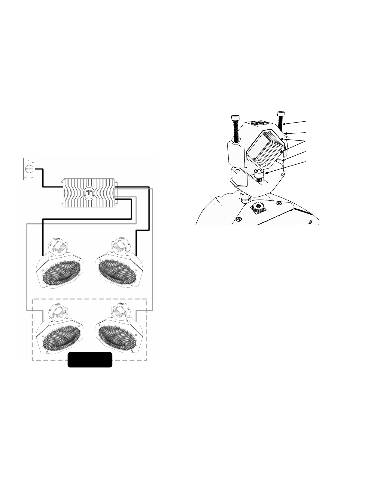
Using the above image for reference, remove the top clamp bolts and top clamp.
Loosen the bottom clamp bolts so the bottom clamp can turn freely between the
splines on the underside of the clamp, and the splines on the cabinet. You can now
choose the spline location to choose the best “left/right” alignment. Once chosen,
tighten the bottom clamp bolt to secure the splines together.
Attaching the speakers: Once you have chosen a good location, and have the
“left/right” alignment set, its time to attach the speakers to the machine. The bolts
that came in the clamps during shipping will be long enough for most installations.
You will see a second set of longer bolts that came in the bag with the rubber clamp
inserts. These additional bolts are used for tube diameters of 2.0”. Using the above
image for reference, make sure you place the “rubber clamp inserts” between the
clamp and the tube of the machine. Put the top clamp over everything, and using the
correct length bolts, secure the clamps to the machine. Note: The top and bottom
clamps are made of cast aluminum. Although they are very strong, we suggest
securing the clamp bolts using hand tools instead of powered or pneumatic tools.
5
Top Clamp Bolts
Top Clamp
Rubber Clamp Inserts
Bottom Clamp
Bottom Clamp Bolt
With everything adjusted, please take a few minutes and “clean up” any wiring
making sure it is properly secured to the vehicle. Have a seat in the vehicle and
make sure the speaker placement, or the placement of any of the parts of this kit
will not impede the safe operation of the vehicle. Now is a good time to use the
heatshrink to cover the audio out plug for BT1 where it plugs into the amp.
With everything properly secured, the system is now ready to enjoy!
8
UTV 1 Basic System Flow Chart
Optional 2nd Set Of
Element 1 Speakers

Wiring the speakers: The speakers conveniently have 1 meter (3.3’) of wire coming
out of each cabinet. The weatherproof connectors at the end of this wire will plug
into the supplied 12’ (3.36m) as explained in the amplifier section of this manual.
Once you have the speakers mounted and wired, use “zip ties” to properly secure
the wires to the vehicle. Make sure any “left over” wire does not impede the safe
operation of the vehicle.
IMPORTANT: Before operating the vehicle, make sure the speakers are mounted
and secured properly, and WILL NOT IMPEDE THE LINE OF SIGHT FOR THE DRIVER
WHICH COULD CAUSE UNSAFE OPERATION OF THE VEHICLE!
Pairing And Controlling BT-1
Pairing BT-1 to your wireless device: BT-1 is always discoverable and requires no 4
digit code. With BT-1 powered on, you will see a flashing blue led. When the light is
flashing, UTV-BT is not paired to any device. Go to the settings area of the wireless
device you are trying to pair, and make your device “discoverable”. In the list of
available devices, look for “Metrix Audio UTV” and select that. Once paired, the led
on BT-1 will stay on solid. Once initially paired, BT-1 will auto pair to your device.
BT-1 will auto pair with up to 9 devices.
Turning BT-1 On/Off: Press and hold the control button for 3 seconds to turn the
unit on, at which time a red LED will turn on. Press and hold for 3 seconds to turn
the unit off. No lights will be illuminated when the unit is off. This function also
turns the Element X amplifier on and off.
Play/Pause: Tap the control button once to pause the unit. Tap the control button
again to resume playing.
Volume Up: Push the main control knob in, and at the same time turn it to the right
(clock wise).
Volume Down: Push the main control knob in, and at the same time turn it to the
left (counter clock wise). Depending on the Bluetooth music player you are using,
the Volume Up/Volume Down functions will control the volume level of MOST
devices. If this does not work for your device, you will need to make sure you have
the volume of your device up high enough to be heard through your audio system.
Skip Track Forward: Without pushing it in, turn the control knob to the right
(clockwise) This allows you to “skip forward” to the next song saved on your
Bluetooth® device.
6
If you are installing a second set of Element 1 Speakers at the same time
as this kit, the second set will plug right into the “EXT” outputs on
the amplifier. When running 2 pairs of Element 1 speakers, the
amplifier “drops” to 2 ohms stereo, and is rated to
produce 125 watts per channel.
Skip Track Backward: Without pushing it in, turn the control knob to the left
(counter clockwise). This allows you to go back to the start of the song your
currently listening to. Depending on the Bluetooth® device our paired to, in most
cases turning it a second time will go to the start of the song on your device before
the one your currently listening to.
AUX In: Tapping the main control knob twice (fairly quickly) allows music be heard
through something plugged into the Aux In cable from a peripheral device such as a
GPS or satellite radio. When BT-1 is in AUX mode, the AUX light (circle with arrow)
will illuminate. You will no longer be able to hear your Bluetooth® device when the
AUX logo is lit. Tap the main control button twice again, and the AUX light will go
out indicating the unit is now out of AUX mode. Your Bluetooth® device can now be
used and controlled by the main control knob. Important: When the unit is in AUX
mode, the main control knob does not control anything to do with the peripheral
audio device! Main system volume will still work though.
Adjusting the Element X Amplifier
The amp comes set from the factory pretty much “set to go” for this kit, but just in
case, please double check the settings before testing the system. The extra controls
on the amplifier are to make sure this system is fully expandable as more Metrix
Audio UTV specific products become available in the future.
Remove the rubber plug directly below the silkscreen on the end of the amp. You
will see a 3 position switch labeled HP, LP, and AP. For this kit, the switch should be
on “HP”. The input select should be in the “low” (button in) setting.
Adjusting the gain: Please note that the gain is set from the factory to work great
with the BT-1 receiver controller and should not require adjustment! There is a
rotary dial behind the rubber plug marked “gain”. It is very important to know that
GAIN IS NOT THE VOLUME DIAL! The intent of a gain adjustment is to make it so
when BT-1 is at 60% of its volume, the amp is at 60% of its “power swing”. Having
the gain set too high on the amplifier will cause your system to sound distorted
before it should. To set the gain on the amplifier, start with the gain all the way off
(counterclockwise). Put the BT-1 so its volume is approximately 75% of the way up.
Start turning the gain dial to the right until the point you hear distortion (sounds
like it breaking up) and leave it alone.
7
IMPORTANT: MAKE SURE TO PUT THE RUBBER PLUG BACK ON AMPLIFIER
Damage to the amplifier may occur which is not covered by warranty!
Table of contents


