Tokheim ProGauge MAGLINK LX User manual

MAGLINK LX
Rev. 09, – April 2016

MAGLINK LX
Installation Manual
| ummary
Rev. 09,
– April 2016
Page 2 of 24
S
UMMARY
1
PREFACE ............................................................................................................................................................. 3
2
GENERAL WARNINGS ......................................................................................................................................... 3
3
INTRODUCTION .................................................................................................................................................. 4
4
GENERAL INDICATIONS ...................................................................................................................................... 5
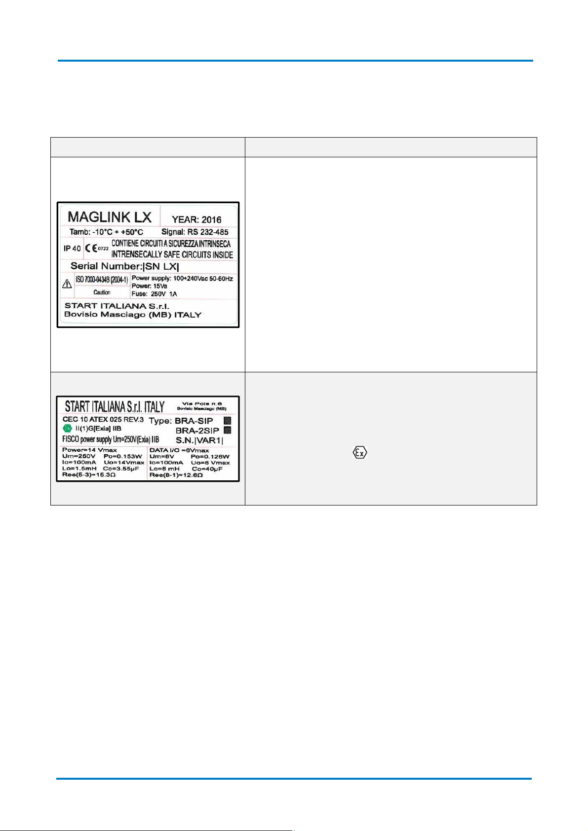
4.1
L
ABELLING AND TYPE DE IGNATION
............................................................................................................................ 7
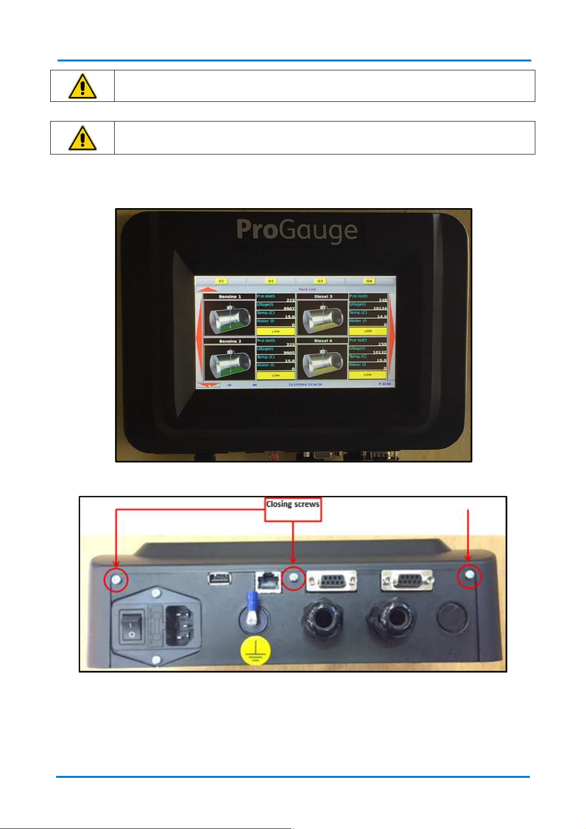
5
INSTALLATION .................................................................................................................................................... 8
5.1
P
RELIMINARY WARNING
. ........................................................................................................................................ 8
5.2
P
LACE OF IN TALLATION
.......................................................................................................................................... 8
5.3
E
LECTRICAL CONNECTION
......................................................................................................................................... 8
5.4
I
N TALLATION PROCEDURE
....................................................................................................................................... 9
6
MODES OF COMMUNICATION ..........................................................................................................................11
6.1
C
ONNECTION TO INTRIN ICALLY AFE
XMT- I-485
PROBE
........................................................................................... 12
6.2
C
ONNECTING THE
XMT
EXPLO ION EXECUTION
.......................................................................................................... 13
6.3
C
ONNECTING THE
RF
R
ECEIVER
(
FOR
XMT- I-RF) ..................................................................................................... 14
6.4
I
NTERFACE TO RELAY DIAGRAM OF CONNECTOR
......................................................................................................... 15
6.5
M
ODEM
C
ONNECTION
.......................................................................................................................................... 16
6.6
DVD
CONNECTION
............................................................................................................................................... 16
6.7
D
IP WITCH
C
ONFIGURATION
.................................................................................................................................. 17
6.8
M
ICRO
D
C
ARD
.................................................................................................................................................. 17
6.9
C
LO ING AND TART UP
......................................................................................................................................... 18
6.10
C
ONNECT THE CON OLE TO THE MANAGEMENT Y TEM
............................................................................................. 19
7
MAINTENANCE ..................................................................................................................................................21
8
SUPPORT ...........................................................................................................................................................22
9
SAFETY INSTRUCTIONS ......................................................................................................................................22
10
REVISIONS .........................................................................................................................................................23

MAGLINK LX
Installation Manual
| Preface
Rev. 09,
– April 2016
Page 3 of 24
1P
REFACE
tart Italiana .r.l. has made every effort possible so that this document is complete, accurate and updated.
With every revision of the console, the corresponding information is periodically added to the document.
tart Italiana .r.l. reserves the right to make unannounced improvements and/or changes in the product
and/or associated programs. tart Italiana .r.l. is not liable for damages of any kind, including those
resulting in the document, including typographical errors.
Making copies, citing quotes or other reproductions of all or part of this document is permitted only after
written consent of tart Italiana .r.l.
Trade mark or name is protected by patents.
Copyright 2015© tart Italiana .r.l. – All rights reserved
2G
ENERAL
W
ARNINGS
Before working on this equipment, please be certain to carefully read the instructions in this manual.
Configuration must be performed by properly trained personnel.
The manufacturer is not responsible for any operation performed which is not covered in this manual.
Any tampering with the equipment and software relieves the manufacturer of any responsibility in regards
to competent bodies.
In case of failure or defect, refer to an authorized service provider or manufacturer directly.
The manufacturer accepts no responsibility for any injury and/or damage to persons and/or property
and/or pets caused by failure to follow instructions relating to safety.
Qualified and trained staff has to know all safety requirements in this manual, in the user manual and in the
installation manual.
In case of doubt concerning the operation of the equipment, refer to an authorized service provider or
manufacturer directly.
IMPORTANT: It is compulsory to consult safety instructions before using the equipment
IMPORTANT: Improper use, not in accordance with the requirements described herein, may
compromise safety

MAGLINK LX
Installation Manual
| Introduction
Rev. 09,
– April 2016
Page 4 of 24
3I
NTRODUCTION
The present manual has been prepared in accordance with IEC 82079-1 standards. “Preparation of
instructions for use - tructuring, content and presentation - Part 1: General principles and detailed
requirements”and according to the ATEX Directive 2014/34/EU concerning equipment and protective
systems intended for use in potentially explosive atmospheres.
The manual provides all necessary information about installing the Maglink LX console.
ATTENTION: This manual must be used in conjunction with the following manuals:
•Console Configuration
•User Manual
To use the console, you must install the console as described in this manual, configure the
console as a reference manual, and use the console on the field as reference manual
The Maglink LX console complies with the requirements of Directive 2012/19/EC on waste of electrical and
electronic equipment (WEEE) and hence displaying the according symbol:
IMPORTANT: The crossed out wheelie bin symbol indicates that the product, at the end of its
useful life, must be disposed of with household waste and must be brought to a collection
point for electrical and electronic equipment
The following table lists reference data of the manufacturer:
D t Description
Name TART ITALIANA .r.l.
Address
Via Pola 6
20813 Bovisio Masciago (MB)
Italia
Telephone +39 0362 1581465
Fax +39 0362 1581464
Website www.startitaliana.it
e-Mail [email protected]
The following table lists the symbols used in the document:
Symbol Description
ATTENTION: Important information and notes regarding operations and use
considerations
IMPORTANT: Danger to persons (including death), to property or to the
environment
ATTENTION: The units of measurement contained in this manual refer to a specific choice
by the user himself/herself. You can set the measurement units in a different way (see
ection 6.1 of this manual).

MAGLINK LX
Installation Manual
| General information
Rev. 09,
– April 2016
Page 5 of 24
4G
ENERAL
I
NDICATIONS
The Maglink LX console is shipped in a cardboard box (L 320 x H 224 x D 90 [mm]) and includes the
following:
•MAGLINK LX console
•Connection cable of 220 V with chuko plug
•Check-list certifying quality control
•User manual and installation manual
Weight of console with carton box: 1 kg.
The following image shows the console upon opening of the box:
The following table lists the principal technical characteristics of the console:
Element Ch r cteristic
Display Display TFT 7 inch
Dimensions 155 x 88 [mm]
Console
Dimensions
•Width 267 mm
•Height with cable: 215 mm
•Depth 80 mm

MAGLINK LX
Installation Manual
| General information
Rev. 09,
– April 2016
Page 6 of 24
The following image shows the lower part of the console:
The following table lists the elements in the figure:
Element Description
U B For firmware updates and back-up of the console (Refer to the "User Manual")
RJ45 For console configuration, and local network connections (Refer to the "Console
Configuration" manual)
R 232 com 1 erial port for connection to management systems (FCC/PO )
R 232 com 2 erial port to a local printer connection and possibility of duplicating the Gilbarco
protocol output required for DCD connections (Refer to the "User Manual")
Connections for
grounding the
system
For ground connections of the internal intrinsically safe barrier

MAGLINK LX
Installation Manual
| General information
Rev. 09,
– April 2016
Page 7 of 24
4.1 Labelling an type esignation
The following table lists the labels placed on the equipment:
L belling Description
The labelling on the outer container contains the following
data:
•Name and address of the manufacturer
•CE marking with the Notified Body
•Product Name
•The "Caution" symbol (0434B of 01/2004), according to
I O 7000
•erial number
•Year of production
•Power upply(VAC and Hz)
•Power consumption (VA)
•Operating temperature (°C)
•Ingress protection (IP grade)
•Fuse rating
•Indication that inside there is intrinsically safe circuit
ATEX labelling on the outer container contains the following
data:
•Name and address of the manufacturer
•Equipment Type (BRA- IP, or BRA-2 IP)
•ATEX Reference number of the certificate
•ATEX Marking: II (1) G [Exia] IIB FI CO power supply
UM=250 V [Exia] IIB
•erial number
•Electrical data

MAGLINK LX
Installation Manual
| Installation
Rev. 09,
– April 2016
Page 8 of 24
5I
NSTALLATION
5.1 Preliminary warnings.
IMPORTANT: The MAGLINK LX console is not explosion-proof
IMPORTANT: Explosions and fires can cause damage or even death
IMPORTANT: Flammable vapours when mixed with air can cause an explosion. Dangerous
areas can occur from the presence of gases or vapours
IMPORTANT: Do not install the console in a hazardous area
IMPORTANT: Only use fuses of 250 V - 1 A for input power
5.2 Place of installation
You must consider that the console was not designed to withstand vibrations and extreme climatic
conditions (High and low temperatures, humidity, etc.) which can damage the electrical circuits when
selecting the console installation site.
ATTENTION: Install the console in a place that is protected from moisture and water splashes
IMPORTANT: The console must be installed in safe area
5.3 Electrical connection
The following table shows the steps necessary for the electrical connection to a 220 VAC:
Step Description
1 Turn off all power switches on the electrical panel
2 Connect the electrical panel and the console using the appropriate connectors
3
For power connections, use a single-phase cable, a section of which is not less than 1.5 mm
2
and
one which is adequately protected. The power cord must comply with the standards IEC 60227
and IEC 60245. The cable supplied with the console already complies with regulations.
4 Make sure the power plug is connected to the ground and protected against short circuits and
power surges
5 The power cord must be easily recognizable and accessible as it also has the function of removing
power

MAGLINK LX
Installation Manual
| Installation
Rev. 09,
– April 2016
Page 9 of 24
IMPORTANT: There is high voltage inside the console.
IMPORTANT: The electrical connection procedure must be performed by trained and
authorized personnel
5.4 Installation proce ure
The following image shows the console attached to the wall:
The following image shows the three mounting screws that allow console opening/closing:

MAGLINK LX
Installation Manual
| Installation
Rev. 09,
– April 2016
Page 10 of 24
The following image shows the console opened (Lift the top and disconnect the ribbon cable that connects
the top and lower parts):
After disconnecting the ribbon cable fix the rear part to the wall (We recommend using Fischer dowels, size
6). The following image shows the mounting holes:
After attaching the console to the wall, you must run the wiring of the sensor cable to the console, as
explained below.

MAGLINK LX
Installation Manual
| Connections
Rev. 09,
– April 2016
Page 11 of 24
6M
ODES OF COMMUNICATION
The following image shows the open console (front panel removed as explained above):
The following table lists the items at the bottom of the console:
Element
Description
1 P U protection panel
2 BRA-2 IP barrier for connection to the probes (8+8)
3 Interface to relay

MAGLINK LX
Installation Manual
| Connections
Rev. 09,
– April 2016
Page 12 of 24
6.1 Connection to intrinsically safe XMT-SI-485 probe
The following figure shows how to connect the intrinsically safe probe (XMT- I-485 model), on the BRA-2 IP
barrier type:
The following table lists the connections shown in the figure:
Connection
Specific tions
MR1
Barrier Input
MR3
Output below the safety barrier (up to 8 probes)
Red (+ 12V)
-
Terminal 1
Brown (R 485A)
-
Terminal 2
Blue (R 485B)
-
Terminal 3
White (
-
0 V)
-
Terminal 4
MR4
Output below the safety
barrier (up to 8 probes)
Red (+ 12V)
-
Terminal 1
Brown (R 485A)
-
Terminal 2
Blue (R 485B)
-
Terminal 3
White (
-
0 V)
-
Terminal 4
CN7
Power output and data channel for XMT
-
I
-
485 probes
Not used
-
Terminal 5
White (
-
0 V)
-
Terminal 4
Blue
(R 485B)
-
Terminal 3
Brown (R 485A)
-
Terminal 2
Red (+ 12V)
-
Terminal 1
In the event of installations with more than 16 probes/tanks, you must use the Magdirect connected to the
console MR1 or CN7, each Magdirect carries up to 8 probes

MAGLINK LX
Installation Manual
| Connections
Rev. 09,
– April 2016
Page 13 of 24
6.2 Connecting the XMT explosion execution
The image below shows how to connect your console to an XMT probe explosion:
The XMT model explosion probes must be connected in parallel to the console and directly to the
connector CN7 without passing through the intrinsically safe barrier.
In this case the barrier remains unused.
The following table lists the connections shown in the figure for connector CN7:
Connection
Specific tions
CN7
Not used - Terminal 5
White (-0 V) - Terminal 4
Blue (R 485B) - Terminal 3
Brown (R 485A) - Terminal 2
Red (+ 12V) - Terminal 1

MAGLINK LX
Installation Manual
| Connections
Rev. 09,
– April 2016
Page 14 of 24
6.3 Connecting the RF Receiver (for XMT-SI-RF)
The image below shows how to connect your console to an RF Receiver:
The receiver connects directly to connector CN7 without going through the intrinsically safe barrier.
In this case the barrier remains unused.
Connection
Specific tions
CN7
Not used - Terminal 5
White (-0 V) - Terminal 4
Blue (R 485B) - Terminal 3
Brown (R 485A) - Terminal 2
Red (+ 12V) - Terminal 1
For proper connections of the receiver, you must refer to the installation manual of the RF Receiver
( ection on electrical connections).

MAGLINK LX
Installation Manual
| Connections
Rev. 09,
– April 2016
Page 15 of 24
6.4 Interface to relay iagram of connectors
The following image shows the connectors of a Maglink LX slave console:
The following table lists the console connectors:
Connector
Specific tions
Connector
Specific tions
CN1
CANBU Conn
for DVD probes
CN8
Power input (13 VDC)
1
CANH
1
+12 V
2
CANL
2
GND
3
GND
3
Not used
CN2
Relay 1 connector
CN10
Digital input connector (Activated with a
positive voltage)-DEEP 3 OFF
1
Normally Closed
2
Common
1 GND (activated with a positive
voltage)
3
Normally Open
CN3
Relay 2 connector
2
Input 1
1
Normally Closed
3
Input 2
2
Common
4
Input 3
3
Normally Open
5
Input 4
CN4
Relay 3 connector
6
Input 5
1
Normally Closed
7
Input 6
2
Common
CN10
Digital input connector (Activated with a
positive voltage)-DEEP 3 ON
3
Normally Open
CN5
Relay 4 connector
1 GND (activated with a positive
voltage)
1
Normally Closed
2
Common
2
Not Enabled
3
Normally Open
3
+12 VDC (theft protection)
CN7
R 485 port
4
Not Enabled
1
Red (+12 V)
5
Not Enabled
2
Brown (R 485A)
6
Not Enabled
3
Blu (R 485B)
7
Not Enabled
4
White (
-
0 V)
CN11 Main board connector
5
Not used

MAGLINK LX
Installation Manual
| Connections
Rev. 09,
– April 2016
Page 16 of 24
The following table lists the console connectors and the meaning of the different LEDs present:
Connector
Specific tions
V1
Modem connector/IF F (optional)
LED1
Power LED output to probe
L1
Relay 2 status LED (Lit:
relay energised)
L2
Relay 3 status LED (Lit: relay energised)
L3
Relay 4 status LED (Lit: relay energised)
L9
Input 6 status LED (Terminal 7)
L10
Input 5 status LED (Terminal 6)
L11
Input 4 status LED (Terminal 5)
L12
Input 3 status LED (Terminal 4)
L13
Input 2 status LED (Terminal 3)
L14
Input 1 status LED (Terminal 2)
L19
Relay 1 status LED (Lit: relay energised)
6.5 Mo em Connection
Connection of the GSM modem
Basic operations:
1. Disable the PIN code from the SIM card before insert it into the modem.
2. Insert the SIM card into the dedicated slot of the modem
3. Po er on the console and ait some time to allo to the modem to
connect to the GSM net ork. When connected the GSM signal depth ill
appear on the display of the console.
6.6 DVD connection
DVD has CAN bus communication and has to be connected to CN1
The power supply has to be bypassed through relay nr. 4 since the Maglink LX will power the DVD only
when it is necessary activating or deactivating the relay nr. 4.
When DVD is configured Relay nr.4 is not available for any alarm settings

MAGLINK LX
Installation Manual
| Connections
Rev. 09,
– April 2016
Page 17 of 24
6.7 Dipswitch Configuration
The following picture shows the inside of the upper side of the console if you observe the dipswitch you can
choose different configurations:
The following table shows the configuration of the dipswitch:
Dipswitch Description
1 OFF = single Gilbarco, ON = Double Gilbarco (required for DCD connections)
2
OFF = Internal inputs not available for alarms, but are used for other control functions
On = Internal inputs available for alarms
3
OFF = Automatic alarm mode off
ON = Anti-theft mode (Dipsw 2 must be OFF)
With 3 + 12 V DC CN10 connection Terminal and 1 0 V DC Terminal
4 OFF = Relay in normal mode, ON = Relay in reverse
6
General Reset
(Turn off the console, switch to ON, turn on the console, wait for the display
cursor in the top left to flash, turn off the console, switch to Off, turn on the console)
ATTENTION: The general reset results in loss of all configuration data, the
historical, alarms, delivery and reconciliations
7 OFF = Reconciliation deactivated, ON = Reconciliation activated
Dipswitchs not mentioned are reserved for future use
6.8 Micro SD Car
The following picture shows the inside of the upper side of the console highlighting the micro D card, the
D card supports the operating system, firmware, configuration and a history of the console:

MAGLINK LX
Installation Manual
| Connections
Rev. 09,
– April 2016
Page 18 of 24
ATTENTION: Do not remove the micro D card, the console cannot work
without the D card
6.9 Closing an start up
Re-assemble the top of the console with the lower part fixed to the wall and previously wired.
Connect the power cord and turn on the console.
Continue with the configuration as shown in the "Console Configuration" Manual.

MAGLINK LX
Installation Manual
| Connections
Rev. 09,
– April 2016
Page 19 of 24
6.10 Connect the console to the management systems
The console can be connected via the R 232 port Com 1 on the following operating systems:
•DIALOG
•DOM
•FUEL PO
(VR350
Interface)
•GILBARCO
•ORPAK
•PIGNONE
•RETALIX
•Probe emulation
The following picture shows the connection for the DIALOG Fuel management system:
The following table lists the connection for the DIALOG Fuel management system:
Console (DB9)
DIALOG system (DB9)
PIN 2
PIN 2
PIN 3
PIN 3
PIN 5
PIN 5
---
Connect PIN 4 with PIN 6
The following picture shows the connection for the GILBARCO Fuel management system:
The following table lists the connection for the GILBARCO Fuel management system:
Console (DB9)
GILBARCO system (RJ45)
PIN 2
PIN 8
PIN 3
PIN 1
PIN 5
PIN 4

MAGLINK LX
Installation Manual
| Connections
Rev. 09,
– April 2016
Page 20 of 24
The following picture shows the connection for the DRE ER management system (PIGNONE):
The following table lists the connection for the DRE ER management system (PIGNONE):
Console (DB9)
DRESSER system (PIGNONE) (DB9)
PIN 2
PIN 2
PIN 3
PIN 3
PIN 5
PIN 5
ATTENTION:
It is recommended not to exceed 15 meters for serial connections between console
and management system via R 232.
Other manuals for ProGauge MAGLINK LX
2
Table of contents
Other Tokheim Music Mixer manuals