Tokyo Photoelectric CANA-0010 User manual

DIGITAL LUXMETER
CANA-0010
INSTRUCTION MANUAL
TOKYO PHOTOELECTRIC CO
.,
LTD.

Overview
・・・・・・・・・・・・・・・・・・・・・・・・・・・・・・・・・・・・・・・・
-1-
Safety Precautions
・・・・・・・・・・・・・・・・・・・・・・・・・・・・・・・・
-2-
Before Use
Checking the Contents of the Package・・・
・・・・・・
-4-
1.Component Names and Functions
・・・・・・・・・・・・
-5-
2. Measurement
・・・・・・・・・・・・・・・・・・・・・・・・・・・・・・・・・・・
-7-
3. Communication Functions
・・・・・・・・・・・・・・・・・・・・・・・
-9-
4. Characteristics of Relative Visible-Spectrum
Response
・・・・・・・・・・・・・・・・・・・・・・・・・・・・・・・・・・・・・・・・
-10-
5. Chracteristic of Oblique Incident Light
・・・・・・・・・・
-11-
6.
Specifications
・・・・・・・・・・・・・・・・・・・・・・・・・・・・・・・・・・・・
-12-

-1-
Overview
Thank you for purchasing the digital lux meter.
This user’s manual primarily explains the handling precautions and
basic operations of the digital lux meter.
To ensure correct use, please read this manual thoroughly before
beginning operation.
The CANA-0010 is light and small, enabling Lx measurements
with the light detector with a liquid crystal display(LCD) for ease of
reading.
The features newly available from this model are data-hold function,
timer hold function, automatic power-off function, RS232C serial comuni-
cation.
After reading this manual, keep it in a safe place.
Notes:
The contents of this manual are subject to change without prior
notice as a result of continuing improvements to the instrument’s
performance and functionality. The figures given in this manual
may differ from the actual screen.
Every effort has been made in the preparation of this manual to
ensure the accuracy of its contents. However, should you have
any questions or find any errors, please contact your nearest
Tokyo Photoelectric Co.,Ltd. (Tokyokoden K.K.) dealer.
Trademarks
In this manual, the and TM symbols do not accompany their
respective registered trademark or trademark names.
Other company and product names are registered trademarks
or trademarks of their respective companies.

-2-
Safety Precautions
The general safety precautions described herein must be observed
during all phases of operation. If the instrument is used in a
manner not specified in this manual, the protection provided by
the instrument may be impaired. Tokyo Photoelectric Co.,Ltd.
assumes no liability for the customer’s failure to comply with
these requirements.
Conventions Used in This Manual
Notes and Cautions
The notes and cautions in this manual are categorized using the
following symbols.
Improper handling or use can lead to injury to
the user or damage to the instrument.
This symbol appears on the instrument to
indicate that the user must refer to the
user's manual for special instructions.
WAR
WARNING
Calls attention to actions or conditions that
could cause serious or fatal injury to the user,
and precautions that can be taken to prevent
such occurrences.
CAUTION
Calls attention to actions or conditions that could
cause light injury to the user, or cause damage
to the instrument or user’s data, and precautions
that can be taken to prevent such occurrences.
Note
:
Calls attention to information that is important for
the proper operation of the instrument.

-3-
Make sure to comply with the precautions below.
Not complying might result injury or death.
WARNIN WARNING
Use the instrument Only for Its Intended Purpose
The lux meter is for measuring illuminances.
Do not use this meter for any other purpose.
Check the Physical Appearance
Do not use the meter if there is a problem with its physical
appearance.
Do Not Disassemble
Only qualified Tokyo Photoelectric Co.,Ltd. personnel may
disassemble this product.
Do Not Operate in an Explosive Atmosphere
Do not use this meter in the presence of flammable gases or
vapors. Doing so is extremely dangerous.
CAUTION
The meter is for domestic use (Class B) and meets the
electromagnetic compatibility requirements.
Do not drop the meter or strike it against hard objects.
Avoid storing the meter in direct sunlight or in a humid environment.
Using the meter in an low-temperature environment ( 10°C to 0°C)
may slow down the display’s response.
Avoid using the meter in a dirty or dusty environment or in an
environment with salt or corrosive gases.
Do not wipe the meter with organic solvents.
Dirt or dust adhering to the light-detecting surface of the meter
decreases measurement accuracy.
Wipe the surface clean with a soft, dry cloth.
Do not wet. The meter is not water proof.

-4-
Before Use
Checking the Contents of the Package
Unpack the box and check the contents before operating the
instrument. If the wrong items have been delivered, if items are
missing, or if there is a problem with the appearance of the items,
contact your nearest Tokyo Photoelectric Co.,Ltd. (Tokyokoden K.K.)
dealer.
Standard Accessories
AAA-size alkaline batteries . . . . . . . . . . . . . . . . . . . . . . . . . . 2
Soft-sided case . . . . . . . . . . . . . . . . . . . . . . . . . . .1
User’s Manual (Japanese or English) . . . . . . . . . . . . . . . . . . . .1
* AAA-size alkaline batteries for accessories are for checking of equipment.
-5-
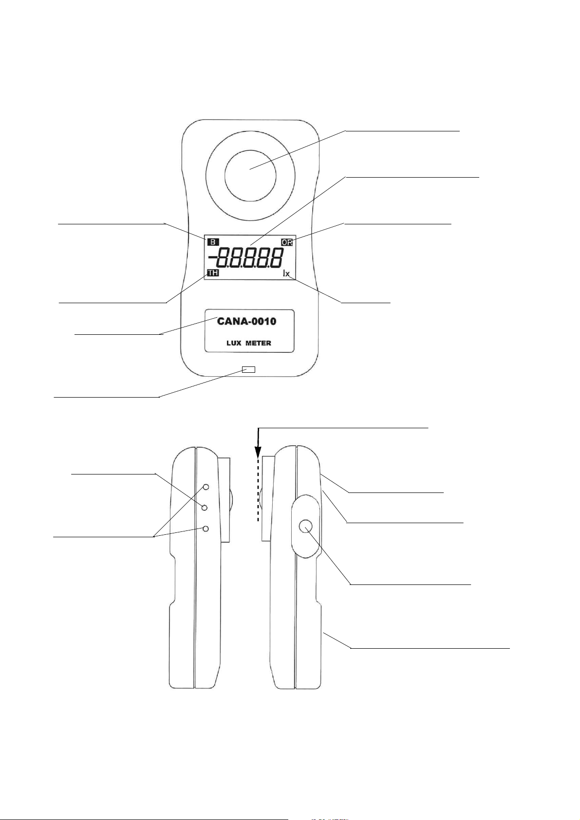
1. Component Names and Functions
Light detecting surface
Measured Value display
Battery Low indicator Over Range indicator
Timer hold indicator Lux Unit
Model name
Use for Strap
(Strap is not atached)
[FRONT]
Measuring reference plane(Dome top)
RS-232C
Digital Output
Product Serial No.(BACK)
For caliblation Simple Manual(BACK)
maker use only
(Users can 'not Use)
Power and Hold switch
Battery case with slide lid(BACK)
[Left side] [Right side]

-6-
[Front]
Light detecting surface
Measured Lux that received light at this plane.
Measured Value display
Display measured Lux value
Over Range indicator
When a measured value is beyond 40000Lx,this mark is blinking.
and shows it is out of a measurement range.
Unit
display
displayunit is lx(Lux).
Blinking means continuous Measurement.
and Lights means that indicate value is hold value.
Battery Low indicator
Lights when the battery voltage is low.
Timer hold indicator
Blinking is in hold timer action and Lighting
indicate value is hold value.
Use for Strap
Strap is not attached.
please attach your strap or a commercial selling.
[Right side]
Measuring reference plane(Dome top)
This insturmens calibrete at Measuring reference plane(Dome top).
Power and Hold switch
This switch use for Power on, Data hold, Timer hold,
return to measure and Power off
* First push Power on and act continuous Measurement.
* When Power is on,
Short time push again activate value hold.
Long time push again(about 3second) activate Timer hold.
* When
Measured Value display
indicate hold value ,
Push return to continuously Measurement.
[Left side]
RS-232C Digital Output
Digital Output for RS232C
connect to the Data cable sold separately.
For caliblation maker use only
Ther are for maker caliblation. User cannnot use them.

-7-
[Back]
Product Serial No.
Product serial number printed here.
Simple Manual
Simple use manual printed.
Battery case with slide lid
Two AAA size battery is stored.
For battery exchange lid is lightly pushed and pulled down.
2. Measurement
2.1 [Before Operation]
Checking and Replacing Batteries if need.
Replace the battery when
B
appears in the display area to indicate
battery exhaustion, or when nothing is displayed even if you push the
right side button.
In replacement, make sure the polarity(+, -)connection is accurate.
Use two AAA type 1.5V alkaline dry cell battely.
2.2 [Measurement]
Turning the Power On,
and starting continuously measurement
Push right side button for an instant.
Display will appear and continuously Lux measurement will be starting.
you can read Lux value in continuously.
*If measured value exceed 39999 lx, then OR indicator will blinking.
Turning the value hold
Push right side button again for an instant.
Display will fix measurement value.
Return to measurement
Push right side button again for an instant.
Display will return to continuously measurement.

-8-
Turning the timer value hold
The timer hold function makes measurements (holds the value)
after the specified time elapses.
If where you are or what you are wearing is going to affect the
measurement, you must move away from the meter. This function
enables you to set the time needed for you to move away from the
meter so that you can make accurate measurements.
In continuously Lux measurement, Push right side button again for a
while(about 3seconds). TH is light and Display will turn [111111]brinking.
That's means going Timer Hold.
After 10seconds, Measured value will be fixed and hold.
Turning the Power Off,
Push right side button again for a while(over 6seconds),
then power will be off.
(when it's in hold mode,power will be off more shortly.)
Automatic Power Off
The meter has an automatic power-off function to prevent unnecessary
battery usage when you forget to turn off the power.
If there is no key activity for about 5 minutes, the meter automatically
turns off.
Pressing side key while the meter is beeping extends the time until the
power turns off for another 5 minutes.
The automatic power-off function is disabled while the RS232C a plug
is inserted in the RS232C output connector function is being executed.

-9-
3. Communication Functions
3.1 Cable Connection and Interface Specifications
You can send measured values for a PC through RS232C disital
communication output.
If you want to use USB communication port on a PC,Please buy bouth
our RS232C connection cable
(We sold separately)
and RS232C to USB
conversion cable(sold commercial)together.
For serial communication via a virtual COM port on PC, Please obey
the instructions of the instruction manual of the conversion cable.
Communication settings
Baud rate: 9600 bps
Parity: None
Stop bits: 1 bits
Data length: 8 bits
Handshaking: None
Received delimiter: Cr Lf
Transmitted delimiter: Cr Lf
3.2 List of Commands
1] Data send request: 'Q',Cr,Lf
answer from PC:aaaaa.a, Cr, Lf [in every second]
[a : ASCII numeric]
2] Data send stop request: 'E',Cr,Lf
3] Request of stop [Auto Power Off]function :'A','X',Cr,Lf
4] Request of act [Auto Power Off]function :'A','O',Cr,Lf
These commands ignored at force power off by side switch
-10 -
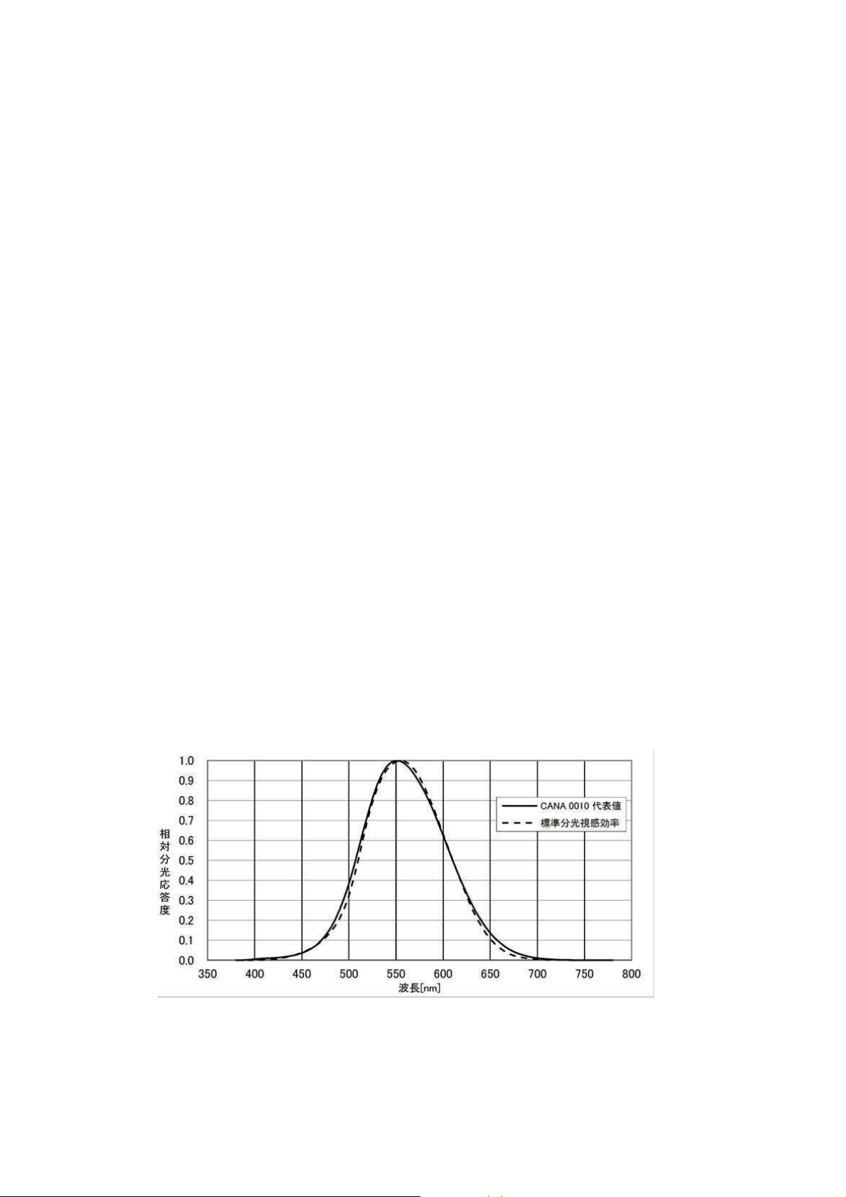
4.
Characteristics of Relative Visible-Spectrum Response
The visible spectrum of light for human beings is from approximately
360nm to 830nm. Even within this narrow range, the sensitivity to light
varies greatly depending on the wavelength. This phenomenon is called
the standard spectral luminous efficiency and is indicatedby V(λ). The
characteristics of relative visible-spectrum response of lux meters play an
important role in illuminance measurement. It is important to approximate
the relative visible-spectrum response to V(λ). These characteristics are
stipulated in engineering standards(JIS C1609-2006)for certified lux meters.
The relative spectral response of an illuminance meter S(λ) is measured
at 5-nm intervals for 95 wavelengths to calculate thedeviation (f1’) from
V(λ). This method of evaluation is based on the performance evaluation
of the Commission Internationale de l’E clairage(International Commission
on Illumination; CIE).There are various light sources such as white light,
fluorescent lamps, and mercury lamps, and LED lamps on the market.
Normally, the relative spectral response of a lux meter is slightly off from
V(λ). So when a light source with a different spectral distribution than the
source that was used to calibrate the lux meter is measured, the readings
will be slightly off. The color correction factor is used to correct this error.
To make accurate measurements, we recommend that you correct the
readings by multiplying the color correction factor of the lightsource under
measurement. The following figure shows the characteristics of the relative
spectral response.

-11 -
5.
Chracteristic of Oblique Incident Light
When reading a book at night, the brightness differs between
reading under a light and reading a little farther from the light.
In such a case, you probably noticed that the book was easier to
read when you faced the book toward the light.
If the angle between the incident light and the line perpendicular
to the illuminated surface is defined to be θ, the illuminance of
the surface is proportional to cos θ.
This characteristic is standardized.
If the lux meter does not meet the standard, illuminance of
oblique incident light cannot be measured accurately.
The following figure shows the characteristic of oblique
incident light.

-12 -
6.
Specifications
JIS_Class :Conforms to Class A of JIS C 1609-1:2006
Photoelectric element:Silicon photodiode
Display :6-digit liquid crystal display (LCD) with unit displays
Maxmum: 39999 lx
(When under1000lx with hold: 999.9)
Overrange display:[OR ]
Low battery voltage display:[B]
Timer hold display [TH ]
Measurement cicle: 2times/s
Automatic power-off:
When the RS232C output plug is inserted approx. 5minutes
after the last key activity.
Can be disabled by inserting of RS232C plug or sending command.
Disital output :mini stereo jack can be used for Rs232C digital output.
(Rs232C connection cable sold separately)
For USB this need bouth our RS232C connection cable and
RS232C to USB conversion cable(sold commercial) together.
Operating temperature and humidity:
-10℃~40℃、80% RH or less (no condensation)
Storage temperature and humidity:
-25℃~70℃、5 to 95% RH (no condensation)
Power supply :Two AAA dry cells
(Ni-MH rechargeable battery can be used)
or power supply units (Sold separately)
Battery life: :Approx. 50 h (when using alkaline dry cells)
Input rating :Approx. 2.5v to 5v DC ± 5% (0.5 W)
Dimensions :Approx. 61(W)×115(H)×29(D)mm
Weight :Approx. 100g(including batteries)
Sold separately option:
*Rs232C connection cable
* power supply units for 100V AC or for USB power supply

-13 -
Tokyo Photoelectric Co.,Ltd.
suehiroBLDG 3F, 24-5, Ayase 5-chome adachiku,Tokyo, 120-0005 Japan
e-mail: tkk@tokyokoden.com
Table of contents
Popular Measuring Instrument manuals by other brands

KRAL
KRAL Volumeter OMG Series operating instructions

Sonel
Sonel MIC-5010 user manual

Ludlum Measurements
Ludlum Measurements 44-157 manual

Endress+Hauser
Endress+Hauser RIA14 Brief operating instructions

Hexagon
Hexagon DIGICO 200 instruction manual

HYDAC International
HYDAC International FMM-P-L Installation and maintenance instructions


