TOLO Steamtec TOLO-E User manual

________________________________________________________________________________
TOLO SAUNA info@tolosauna.com www.tolosauna.com
1
TOLO - E
Steam Generator Manual
DO NOT use locking pliers to over tight the
DRAIN PIPE connection
Please read the manual carefully before installation
and keep the manual for further reference

________________________________________________________________________________
TOLO SAUNA info@tolosauna.com www.tolosauna.com
2
1. Introduction
Thank you for choosing TOLO - E series steam generator with well-designed structure, steady
performance and convenient installation. The steam bath is designed to remove tiredness, relax
muscles and stimulate blood circulation.
For proper installation, operation, maintenance, and the customer’s safety as well, please read all
instructions carefully and keep this manual for further reference.
2. Safety Warning
This appliance is not intended for use by person with reduced physical, sensory or mental
capabilities, or lack of experience and knowledge, unless they have been given supervision or
instruction concerning use of the appliance by a person responsible for their safety.
Supervise children at all times.
Check steam room before restart the controller.
Smoking and alcohol are not allowed inside the steam room.
Leave the steam room immediately when feels uncomfortable.
A ventilation fan is required for the steam room.
This steam generator is for heating up the steam room, please don’t change its functions or
usage by yourself, unless under the help or the guide of someone who can be responsible for
the safety.
When you go out, or may not use steam generator in long time, please DISCONNECT the steam
generator general power supply and general water supply.
3. Install Cautions
If the generator is installed at a place where difficult for customer to access, the water supply
valve must be easy to access for emergencies.
GFCI must be installed on the power supply, and the power supply, power wire, fuse and
breaker must comply with the nameplate on the unit and table 2 in this manual.

________________________________________________________________________________
3
The solenoid valve can endure maximum 0.8MPa (8kg/cm2) water pressure. To protect the
solenoid valve from extremely high water pressure, please turn down the inlet slightly or
install water pressure relieving valve .
Do not install saddle-backed or needle valves on the inlet. Please dredge and clean the pipe
before installation.
No block valve should be installed in the steam pipelines. Strictly no blocked or blended pipe,
otherwise will have negative effect on the flow of steam and condensate. The steam pipelines
should be installed with a slight angle so that the condensate can flow back to the generator
or the steam head.
Steam generator should be installed indoor to avoid frozen. The generator should be installed
and leveled with the arrow pointing upward at an easy-access place, otherwise do not switch
on.
The steam pipeline must be copper pipes or stainless steel pipes, all other material such as
plastic, acrylic should not be used since they cannot endure 150℃or higher temperature.
All inlet and apertures should be sealed to prevent any leakage of steam and to protect the
generator and customers.
Don’t directly drain to the steam room, as water from the water tank is very hot and may
cause serious scald and damage the steam room.
All inlet water pipes and steam pipelines should be built according to the National Standard
and this should be done before sealing the wall.
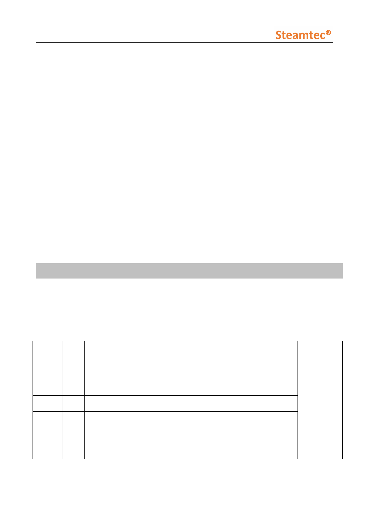
4. Parameters
4.1. Models, parameters and dimension
(Only apply to European style voltage and phase)
Table 2
Model
Power
(kW)
Phase
Heating elements
(N*kW)
Voltage/Current
(V/A)
Power
wire
(N*mm2
)
Breake
r
(A)
Room
volume
(m3)
Dimension
(L*W*H)
(mm)
E-30
3.0
1
2*1.5
220-240/13.6
3*2.5
16
2~3
230*103.5*13
20
E-40
4.0
1
2*2.0
220-240/18.2
3*2.5
25
3~5
E-45
4.5
1
1.5+2.0
220-240/20.5
3*2.5
25
3.5~5.5
E-50
5.0
1
2*2.5
220-240/22.7
3*2.5
32
4~6
E-60
6.0
1
2*3.0
220-240/27.3
3*4.0
40
5~7

________________________________________________________________________________
4
#1: water inlet 1/2’’: #3 :Water drain 1/2’’ #2, #4: Steam outlet;
#5: Electric wire (only 220V single phase), 2 meters, must install Leakage Protection.
#6, #7: communication cable. #8: After-service hole

________________________________________________________________________________
TOLO SAUNA info@tolosauna.com www.tolosauna.com
5
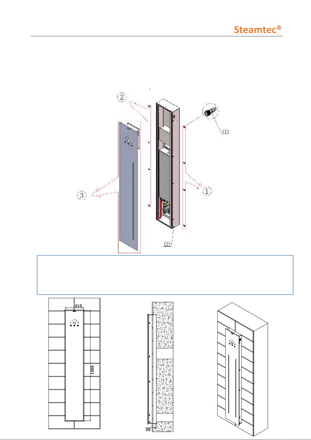
4.1.1. Installation schema
#①#②: the location of screws, unscrew those screws can take off the front glass panel;
#(1): Special screws for fixing the front glass panel;
#③: the front glass panel (fragile, be careful )
#(2): Steam outlet

____________________________________________________________________
____________
6
5. Operating instructions
Steam generator operation instructions:
ON/OFF the steam generator:
Press the ON/OFF button: turn on the machine, begins to fill in water & heat up etc....
The color light:
The first time press: turn on the lights, and then begins the automatic cycle color
changing.
The second time press: select a color and fix it in that color.
The third time press: turn off the lights.
The color light is only for decorating use, not enough for illumination.
Working time setting:
Default time: 45 mins. Auto off when time arrived.
Working temperature setting:
Default temperature: 45℃
Set point: 35℃, 40℃, 45℃, 50℃, 55℃
Music:
By bluetooth
When connecting the bluetooth, press the button for one time.
After well connected, press the button means change into the following song.
Can't control volume on the steam generator.
Can't turn off the music on the steam generator.
Power range: 4.5KW & 6.0 KW
Voltage and phase: EU type: 220V single phase only; USA type: 220V 2 phases only.
Ways for installation:
The steam generator body is inserted into the wall, but not fully inserted.
Water inlet: on the back side of the steam generator, 1/2'';
Water outlet: on the back side of the steam generator, with auto drain valve build in,
3/4'';
Power supply: on the back side of the steam generator; not use terminal blocks, but
with prepared power wire;

____________________________________________________________________
____________
7
Temperature setting:
The temperature setting range is 35℃~55℃(95℉~131℉).
The default setting temperature is 45℃(109℉).
ON/Off
RGB LED Strips
The temperature setting range is
35℃~55℃.The default setting
temperature is 45℃. The smallest dot
is 35℃, the biggest dot is 55℃.
The temperature difference between 2
dots is 5℃.
RGB lights
Press it once, color changes automatically
Press twice, color changes to the color you
want.
Press three times, turn it off.
Music
When you connect the machine at the first
time, you need to turn on your bluetooth
function and search it, the name is
steamtec. You can press it to play next
song

________________________________________________________________________________
8
6. Installation
6.1. Installation cautions
DO NOT use locking pliers to over tight the DRAIN PIPE connection.
Before installation, MUST read all the install cautions in this manual, on page 4.
Selecting the proper steam generator
In order to achieve comfort and relaxation, as well as energy efficiency, the selection of the
correct steam generator model and size are as critical as design of the steam room itself. The
power supply and circuit protector should be carefully checked to match the parameters of the
generator. Please referring to the table 2 & its notice and select the suitable model for your
specification.
6.2. Installation of steam generator body
6.2.1. Cautions
Switch off all power supply before installation, and check whether you have the correct model
for your steam room according to table 2 & its notice .
A manual resetting 120℃temperature control switch is installed in the steam generator for
over-heat protection. If temperature of inner tank exceeds 120℃accidentally, the switch will
automatically disconnect power supply to heating elements. In this case, it is necessary to
disconnect the power supply to steam generator, and then carefully check heating elements,
water level sensor, relay on sub-board and water supply pipeline after steam generator
completely cooling-down. The temperature switch could only be manually reset after the fault
has been located and solved.
Do not install the generator outdoors, in wet/moist place, freezing, or corrosive place. Do not
install the generator near to inflammables such oil paint, diluents and fuel. Be alert to the steam
pipeline and safety valve since the high temperature of steam is dangerous to customers.
Generator must be level installed.
The generator should be installed in a dry and well-ventilated place. It can be installed either on
the wall or on the ground, but must be well fixed. Install the generator as close to steam room as
possible, such as in the closet, under the washing basin or in the basement. (Refer to figure 3).
6.2.2. Cautions
The controller wire and temperature sensor wire should NOT be parallel to or intersect with
the power wire. The temperature sensor should NOT be installed on the side of the wall
which is behind the door, when the door is opened and the controller should NOT be
installed in any moist place.
6.2.3. Installation of controller
The controller should be installed with height of 1.2 m outside the steam room but nearby

________________________________________________________________________________
9
or other place where easy to operate. Use 3M glue fixation or glass glue fixation to settle it
on the wall.
Installation Of Control Wire: there are two connection cables on the controller, put the 4 pin
cable connected with the controller aviation plug(Refer to figure 4).
Caution: The temperature wire should NOT be parallel to or intersect with the power wire.
Caution: The temperature sensor should NOT be installed on the side of the wall which is behind
the door when the door is opened.
i. Water Inlet
First connect the water magnetizer (if applicable) to the water inlet solenoid valve. Then please
use a 1/2’’ flexible stainless steel hose to connect the other side of the water magnetizer and the
water supply pipeline. Do not connect to metal water supply pipeline directly because which
may damage the water inlet valve.
Attention: Only use cold water supply.
ii. Drain Outlet
Please use 1/2’’ copper pipe or stainless steel pipe to connect the drain outlet and the drain
pipeline of the house. The drain pipeline should be installed with small angle so as to help
residual water in the steam generator flow to the drain pipe.
Attention: Don’t use locking pliers to over tight the drain pipe connection. Just make sure it
without leakage under Teflon tape sealing. The water come out from the steam generator will
over 100℃. Don’t use the plastic pipe/acrylic pipe/FRP pipe or other similar material pipe.
iii. Steam outlet
Use copper or stainless steel pipe to connect the steam head and the steam outlet pipe of the
generator. The pipe should be less than 3 meters long and minimize the number of elbows,
otherwise heat isolating methods should be implemented.
For steam generator, steam outlet is 1/2’’, please use AT LEAST 1/2’’ steam pipe, must be
stainless steel pipe or copper pipe.
Attention: Please MUST choose right diameter pipe size, as if the pipe size is smaller than our
instruction, it may cause the steam generator internal pressure to increase suddenly which may
damage the steam generator and have safety risks.
6.3. Installation of electrical
Cautions
All circuits should be installed by licensed electricians and conform to local and national codes.
Power supply must be cut off before installation, maintenance and repair. Press the on/off

________________________________________________________________________________
10
button on the controller cannot cut power from the supply.
No additional power supply or wire is allowed to connect to the generator. Do not connect the
ground wire to the neutral wire.
Only the original parts and elements from our factory are allowed to be used in installation,
operation, maintenance and repair.
After the installation of the pipeline and electrical circuits, carefully checking must be
performed before switch on the generator.
The generator has been carefully installed, checked and tested in factory, thus customer only
need to install the power wire,control wire and temperature sensor etc.
The power supply should be 215-240V or 380-415V, 50/60Hz, please refer to the nameplate of
the generator.
The selection of fuse and breaker must strictly follow the data in table 2.
Choose the suitable power wire according to table 2 and local codes.
Take off the back cover of the generator, insert the 3-core power wire (single phase, 215-240V,
50/60Hz ) into the hole at the back of the generator case and connect to the correct terminal.
6.3.1. Wiring diagram
Steam generator Schematic Diagram
-
+
Over-heat protection
Water
inlet
Heat
Draingage
Water
inlet
+
+ +
1
2
Heat
12v- 12v- 12v+
12v+
DC-12V① DC-12V②
Water
inlet DraingageGND
GND GND 12v+
GND
LOWHigh DrainTemp
GND R
LGNDR B
G+12V
illumination horn
Water level
LNE
-
L
N
+
DC-12V-2A

________________________________________________________________________________
11
7. Maintenance
As leakage of the steam will damage the equipment. To prevent any hazard, steam generators,
steam head, parts and pipe line connections should be checked regularly.
Clean the solenoid valve, magnetizer and all the other sets in the pipe line regularly according to
the local water quality and usage of the steam generator.
When operate, check the equipment to see whether it’s over heated, check the stability and
corrosion of all the wire plugs.
i. Replace the heating elements:
Switch off the steam generator and remove the element access cover when the generator
completely cools down. Label the wires connect to the heating elements which need to be
replaced and plug out the wires. Screw the heating elements out. Clear the scale in the
water tank and screw in the heating elements after putting the rubber rings on them
(airproof gasket should be pressed firmly without reversion). Plug on the wires, make sure
the heating elements are properly connected before put on the element access cover.
ii. Replace the main board:
Switch off the steam generator and remove back cover when the generator completely cools
down. Label the three wires which connect the upper part of the main board to the water
level sensor and the source, drain valve and water inlet solenoid valve in the bottom part of
the main board. Unplug these wires and remove the main board (be careful with
yellow-green ground wire under the screws of the circuit board). Install the main board back
carefully.
iii. Replace the sub-board:
Switch off the steam generator and remove the back cover when the generator completely
cools down. Unplug all the wires on the sub-board. Label all the wires on the relay and
remove the sub-board. Install the sub-board back carefully.
iv. Replace the solenoid valve, drain valve:
Switch off the steam generator and disconnect from the power and water supply. Remove
the water inlet, steam outlet and draining pipelines after the generator completely cools
down. Then please lean the steam generator to remove the base panel. After that, please
take off the soft pipes, wires and screws so that the faulty valve could be removed. Finally
please install the replacing valve carefully.
Cut off the power supply before any maintenance.
Test the equipment after maintenance.

________________________________________________________________________________
12
8. Warranty And Services
Table 3 E Warranty Time (1 year)
Remark:
(1) Warranty period will count from the ex-factory date of the steam generator.
(2) Limited free warranty only including provide free spare parts and our remote services, not
including any other direct or indirect costs / losses.
(3) Limited warranty is offered to all customers. Any quality problem will be covered according
to above file. Please provide the maintenance record (Regular descaling records) when you
ask for warranty.
(4) The controller warranty for 2 year is under install it outside the steam room. Inside the
steam room, controller warranty is 1 year.
(5) Our company has the right to decide whether to repair or to change. Approval must be
obtained from our company before shipping back the product. The customer has to pay for
the transportation fee and any parts fee beforehand.
(6) Any clause mentioned in the manual is not covered by the warranty.
(7) This warranty does not cover any defect, malfunction or failure cased by, or resulting from
unauthorized installation, maintenance and repair, improper power supply, and any action
which violates the manual.
(8) Damage caused by accident, misusing of chemistry products, or any other reason which are
beyond our company’s responsibilities will not be covered. Any product whose label,
nameplate has been removed, altered, damaged is not covered either.
(9) Using in a salty environment or any other extreme, corrosive condition is not covered by the
warranty.
(10) After the free warranty period, services are still available if all cost is covered by the
customer.
(11) Our company is not responsible for any direct or indirect damage caused by the generator.
(12) Please contact our company for further information and more details.
(13) Tips for maintenance:
How to descale Tolo E Steam Generator?
Manual periodic cleaning
You can put solution in, and let it stay in water tank for 4-8 hours, then flush.
How frequently should descaling be done?
*For home use: at least once per month
*For commercial use:at least once per week
What solution can be used?
TOLO acid;
Vinegar or lemon juice, mix with water and make concentration around 10%;
Or can use edible cleanser.
More information you need, please feel free to contact us at info@tolosauna.com

________________________________________________________________________________
13
MAINTENANCE RECORD (Regular descaling records)
This manual suits for next models
5
Table of contents