Tomcat RS 26'' Disk User manual

Operating Instructions (EN)
MODELS:
20'' Disk
26'' Disk
28'' DIisk
24'' Cylindrical
24'' EDGE
28'' EDGE
COMMERCIAL CLEANING EQUIPMENT
www.tomcatequip.com
1711 South Street
Racine, WI 53404 (USA)
(800) 450-9824 | (+001) 262-681-6470 VERSION 15.167
©2015 RPS Corporation RS-OP-EN
Read these Instructions before
using the machine.
Read these Safety Messages
before using the machine.
Scan With Phone for more Information
- 2 - RS-OP-EN
INTRODUCTION
This manual is furnished with each new machine. This manual will allow the Operator to get the best performance out of
your RPS manufactured Scrubber-Drier, Sweeper, Burnisher, or Orbital Scrubber. Read this manual thoroughly before
operating or servicing the machine.
This machine will provide excellent performance, but the best results will be obtained at the most minimum costs if:
• The machine is regularly maintained - per the machine Preventative Maintenance instructions provided.
• The machine is operated with reasonable care and caution.
• The machine is maintained with manufacturer supplied parts.
ABOUT THIS MANUAL
TABLE OF CONTENTS: Tells you where to look in the manual.
SAFETY MESSAGES: Section contains important information regarding hazard or unsafe practices of the machine. Lev-
els of hazards are identified that could result in product or personal injury, or severe injury resulting in death.
OPERATION CONTROLS / MACHINE COMPONENTS: Shows you the different machine controls and features.
MACHINE SETUP: Tells you how to setup machine from un-crating to installing squeegee and brushes.
MACHINE OPERATION: Section is to familiarize the operator with the operation and function of the machine.
BATTERY CHARGING: Shows you how to charge the batteries (on-board and off board charging).
MAINTENANCE: This section contains preventative maintenance to keep the machine and it’s components in good work-
ing condition. They are listed in this general order:
• Batteries
• Scrub Brushes
• Adjusting Squeegee
• Service Schedule
• Machine Trouble Shooting
TROUBLE SHOOTING: A list of common problems that may occur.
MACHINE SPECS: Tells you Machine Specifications for the various parts of the machine.
MACHINE INSTALL FORM: Should be filled out upon machine installation and faxed to 1-866-632-6961 or online at
www.rpscorporation.com.
WARRANTY POLICY: Tells you coverage, exclusions and limitations to warranty.
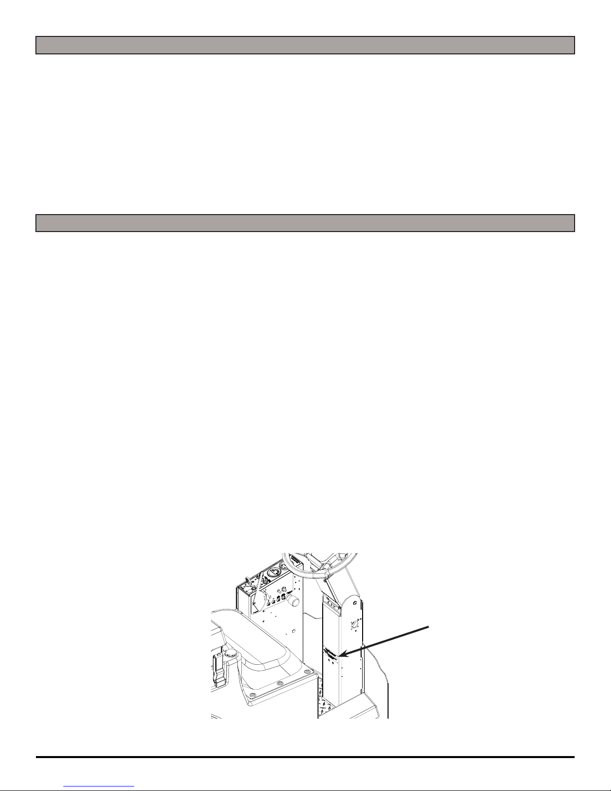
NOTE: The serial number of your machine is located on the lower half of the control panel of the machine.
AS OUR POLICY IS ONE OF CONSTANT IMPROVEMENT - ALL INFORMATION AND
SPECIFICATIONS ARE SUBJECT TO CHANGE WITHOUT NOTICE.
SERIAL NUMBER

RS-OP-EN - 3 -
TABLE OF CONTENTS
Introduction 2
About This Manual 2
Table of Contents 3
Safety Messages 4
Safety Label Locations 6
Operation Controls 7
Operation Controls 8
Machine Components 9
Machine Setup 10
Un-Crating Machine: 10
Connecting Batteries: 10
Adjusting Squeegee: 11
Removing Squeegee: 11
Replacing or Rotating Squeegee Blades: 11
Installing Disk Pad Driver or Brush: 12
Installing Driver Pads: 12
Leveling Disk Decks: 13
Adjust Disk Shroud Wipers: 13
Adjust Disk Shrouds: 13
Installing Cylindrical Brush: 14
Leveling Cylindrical Decks: 15
Adjust Cylindrical Wipers Blades: 15
Installing EDGE Pads: 16
Leveling EDGE Decks: 16
Adjust EDGE Shroud Wipers: 17
Adjust EDGE Shrouds: 17
Machine Operation 18
Pre-Cleaning Checklist: 18
Operating Hints: 18
One Pass Scrubbing: 19
Vacuum Only: 19
Adjust Solution Flow: 19
Draining Recovery Tank: 20
Flush Recovery Tank: 20
Draining Solution Tank: 20
Solution Filter: 21
Cleaning Solution Filter: 21
Squeegee Up: 21
Squeegee Down: 21
Clean Vacuum Screen: 22
Releasing Parking Brake Override Lever: 22
Battery Charging 23
External Battery Charging: 23
On-Board Charger 24
On-Board Battery Charging (Optional): 24
Description of LED 24
Battery Maintenance Guide 25
Safety: 25
Inspection and Cleaning: 25
Storage: 25
Watering: 25
Maintenance 26
Daily Maintenance: 26
Weekly Maintenance: 26
Monthly maintenance: 26
Yearly Maintenance: 26
Storing Machine: 26
Checking Battery Specific Gravity: 26
RS PM Records 27
RS Wiring Guide 29
Trouble-shooting 30
Machine Specs 32
Common Wear Parts 33
Round Disk Brushes: 33
Round Disk Pads: 33
EDGE Pads and Screens: 33
Soap Choices 35
Standard Warranty Policy 37
Machine Install / Warranty Registration 38

- 4 - RS-OP-EN
SAFETY MESSAGES
You will see four kinds of safety reminders in this manual:
DANGER
DANGER indicates a hazardous situation which, if not
avoided, will result in death or serious injury.
WARNING
WARNING indicates a potentially hazardous situation
which, if not avoided, could result in death or serious
injury.
CAUTION
CAUTION indicates a potentially hazardous situation
which, if not avoided, could result in minor or moderate
injury or damage to this machine or nearby objects. CAU-
TION also can be used to alert against unsafe practices.
NOTICE
NOTICE indicates information considered important, but
not hazard-related. This safety message may be related
to property damage or warranty warnings.
Your safety, and that of others, is very important. Operating this machine safely is an important responsibility.
DO NOT OPERATE THIS MACHINE:
• Unless you are trained and authorized to do so
• Unless you have read and understood this Operator’s Manual
• On surfaces with greater than a 2% grade unless this machine is equipped with a functional parking brake
• On surfaces with greater than an 8% grade at any time
WHEN OPERATING THIS MACHINE:
• Remove loose objects from the floor that could be projected from the rotating Brushes
• Keep your hands and feet away from the rotating Brushes
• Do not operate this machine where flammable liquids are present
• Use caution when maneuvering
BEFORE LEAVING THE MACHINE:
• Park the machine on a level surface
• Turn the machine OFF ( )
BEFORE SERVICING THE MACHINE:
• Disconnect the Batteries
DANGER
Explosive hydrogen gas forms when Batteries are
charging. An open flame or spark can cause this gas
to explode. Serious personal injury or property damage
could occur. Only charge the Batteries in this machine in
a well ventilated area.
DANGER
Flammable materials can cause an explosion or fire. Do
not use flammable materials in Tank or pick up.

RS-OP-EN - 5 -
WARNING
The Batteries in this machine produce hazardous
voltage which can cause electrical shock, burns and/
or electrocution. Always disconnect Batteries before
servicing this machine.
WARNING
When climbing or descending ramps, always drive
machine forward. To avoid overturning the machine, Do
not back down ramps. Do not drive across inclines. Do
not turn while ascending or descending ramps. Over-
turning the machine can cause serious injury or death.
WARNING
Do not use water that exceeds 135°F / 57°C. If wa-
ter is above said temperature, this will void the Tank
Warranty.
WARNING
Do not park this machine on ramps or slopes. Always
park this machine on a level, hard surface. Do not oper-
ate this machine outdoors or on uneven surfaces.
WARNING
The Batteries in this machine contain sulfuric acid,
which causes burns to skin. If battery acid contacts
clothing or skin, rinse the effected area with cold water
immediately. If battery acid gets on your face or in your
eyes, flush the area immediately with cold water and
seek medical attention.
WARNING
To avoid electrical shock, do not operate this machine
over electrical floor outlets.
WARNING
Dress safely. Do not wear rings or metal wrist watches
when servicing this machine, as they can cause an
electrical short circuit which can cause serious burns.
WARNING
Do not remove, paint over or destroy warning decals. If
warning decals become damaged, call 1-262-681-3583
for free replacements.
WARNING
Dress safely. Do not wear a neck tie, scarf, or any
loose or dangling clothing while operating this machine.
Loose or dangling clothing or neck-wear can tangle in
rotating parts, causing serious injury or death.
WARNING
Always turn off this machine before leaving it unat-
tended. Do not allow untrained persons to operate this
machine.
WARNING
NO RIDERS. Do not carry passengers on this ma-
chine. Do not use this machine as a stepladder or work
platform.
WARNING
Understand the dynamic braking system before you
operate the machine on ramps. Machine may coast.
WARNING
Before you service a Battery, always wear face protec-
tion, protective gloves and protective clothing. Battery
acid or battery explosion can cause serious injuries.
CAUTION
To avoid damage to this machine, use only cleaning
solutions and replacement parts recommended by the
manufacturer.
CAUTION
Do not operate this machine if any parts have been
damaged or removed.
CAUTION
Always use the automatic battery charger provided by
the manufacturer of this machine to charge the Batter-
ies of this machine. It is designed to charge the Batter-
ies at the appropriate rate. If you must use a different
charger, disconnect the Batteries before charging to
avoid damage to the electronic speed controller.
CAUTION
To avoid damage to the electronic control components
of this machine, Do not store this machine outdoors. Do
not pressure wash this machine.

- 6 - RS-OP-EN
SAFETY LABEL LOCATIONS
Read and obey all Safety Labels on your RS Floor Scrubber. If you have questions about these labels, ask your supervi-
sor.
These images indicate where on the RS Safety Labels are located. If ever the labels become illegible, worn off, or torn,
promptly report it to your supervisor and replace it.
USE ONLY DISTILLED WATER IN THE BATTERIES. USE
ONLY THE OEM CHARGER PROVIDED WITH THE MA-
CHINE. ALWAYS DISCONNECT THE BATTERY BEFORE
SERVICING THE MACHINE.
REFER TO MANUAL OR CALL +011-262-681-3583
DANGER
EXPLOSION RISK!
EXPLOSIVE HYDROGEN GAS FORMS WHEN
BATTERIES ARE CHARGING. AN OPEN FLAME
OR SPARK CAN CAUSE THIS GAS TO EXPLODE.
ONLY CHARGE THE BATTERIES IN THIS MA-
CHINE IN A WELL VENTILATED AREA.
BATTERY CHARGING LABEL
PART #: 250-7290
TO AVOID DAMAGE TO THIS MACHINE:
s53%!002/6%$$%4%2'%.43/.,9
s7!4%24%-0%2!452%-534./4%8#%%$˚F/ 54˚#
s$/./453%()'(0%2#%.4!'%",%!#(-)8452%
REFER TO MANUAL OR CALL +011-262-681-3583
DANGER
EXPLOSION RISK!
&,!--!",%-!4%2)!,3#!.#!53%!.
%80,/3)/./2&)2%$/./453%&,!-
-!",%-!4%2)!,3).4!.+/20)#+50
TANK LABEL
PART #: 5-728
USE ONLYDISTILLED WATER INTHE BATTERIES. USE
ONLYTHE OEM CHARGER PROVIDED WITH THE MA-
CHINE. ALWAYS DISCONNECT THE BATTERY BEFORE
SERVICINGTHE MACHINE.
REFERTO MANUAL OR CALL +011-262-681-3583
DANGER
EXPLOSION RISK!
EXPLOSIVE HYDROGEN GAS FORMS WHEN
BATTERIESARE CHARGING. AN OPEN FLAME
OR SPARKCAN CAUSE THIS GAS TO EXPLODE.
ONLYCHARGE THE BATTERIES IN THIS MA-
CHINE IN A WELL VENTILATED AREA.
TO AVOID DAMAGETO THIS MACHINE:
s
53%!002/6%$$%4%2'%.43/.,9
s7!4%24%-0%2!452%-534./4%8#%%$˚F/54˚#
s$/./453%()'(0%2#%.4!'%",%!#(-)8452%
REFERTO MANUAL OR CALL +011-262-681-3583
DANGER
EXPLOSION RISK!
&,!--!",%-!4%2)!,3#!.#!53%!.
%80,/3)/./2&)2%$/./453%&,!-
-!",%-!4%2)!,3).4!.+/20)#+50

RS-OP-EN - 7 -
OPERATION CONTROLS
1. BATTERY GAUGE / HOUR METER: Indicates the amount of battery charge remaining along with total hours
used - Below 20% and machine goes into “creep” mode to save charge to allow machine to be driven back to
charging station
2. BRUSH MOTOR AMP GAUGE: Indicates amp draw of the Scrubdeck motors combined
3. VACUUM SWITCH [WHITE]: Turns the Vacuum Motor ON ( ) / OFF ( )
4. SOLUTION FLOW SWITCH [BLUE]: Turns solution flow ON ( )/ OFF ( )
5. SCRUBDECK SWITCH [BLACK]: Raises and lowers the Scrubdeck - Scrubdeck turns on automatically when
lowered and foot pedal is pressed
6. KEY SWITCH: Turns power of the machine ON ( ) / OFF ( )
7. REVERSE SWITCH [RED]: Switch to forward position to drive forward - back position for reverse (Alarm will
sound in reverse)
8. SOLUTION FLOW CONTROL LEVER: Adjusts the amount of solution flow delivered to the Scrubdeck ( + / - )
9. CIRCUIT BREAKER: 15 amp Positive Bus Bar ( + )
10. CIRCUIT BREAKER: 15 amp Negative Bus Bar ( - )
11. CIRCUIT BREAKER: 25 amp Vacuum Motor
12. CIRCUIT BREAKER: 30 amp Scrubdeck Motor
13. CHARGER PORT: Plug in grey charger connector here to charge machine batteries (OEM 36 Volt / 25 Amp Only)
14. QR CODE: Scan machine serial QR Code and see all of the machines BornOn Information
15. RECHARGE METER: Indicates amount of times machine has been connected to a charger
16. POWER ON METER: Hour meter to indicate complete time key has been ON ( )
17. DRIVE MOTOR METER (OPTIONAL): Indicates complete time Drive Motor has been in use
18. SCRUBDECK MOTOR METER (OPTIONAL): Indicates complete time Scrub Motor(s) has been in use
19. VACUUM MOTOR METER (OPTIONAL): Indicates complete time Vacuum Motor has been in use
67
1
2
34
5
8
10 11 12
13
17
14
18
15
19
16
9
- 8- RS-OP-EN
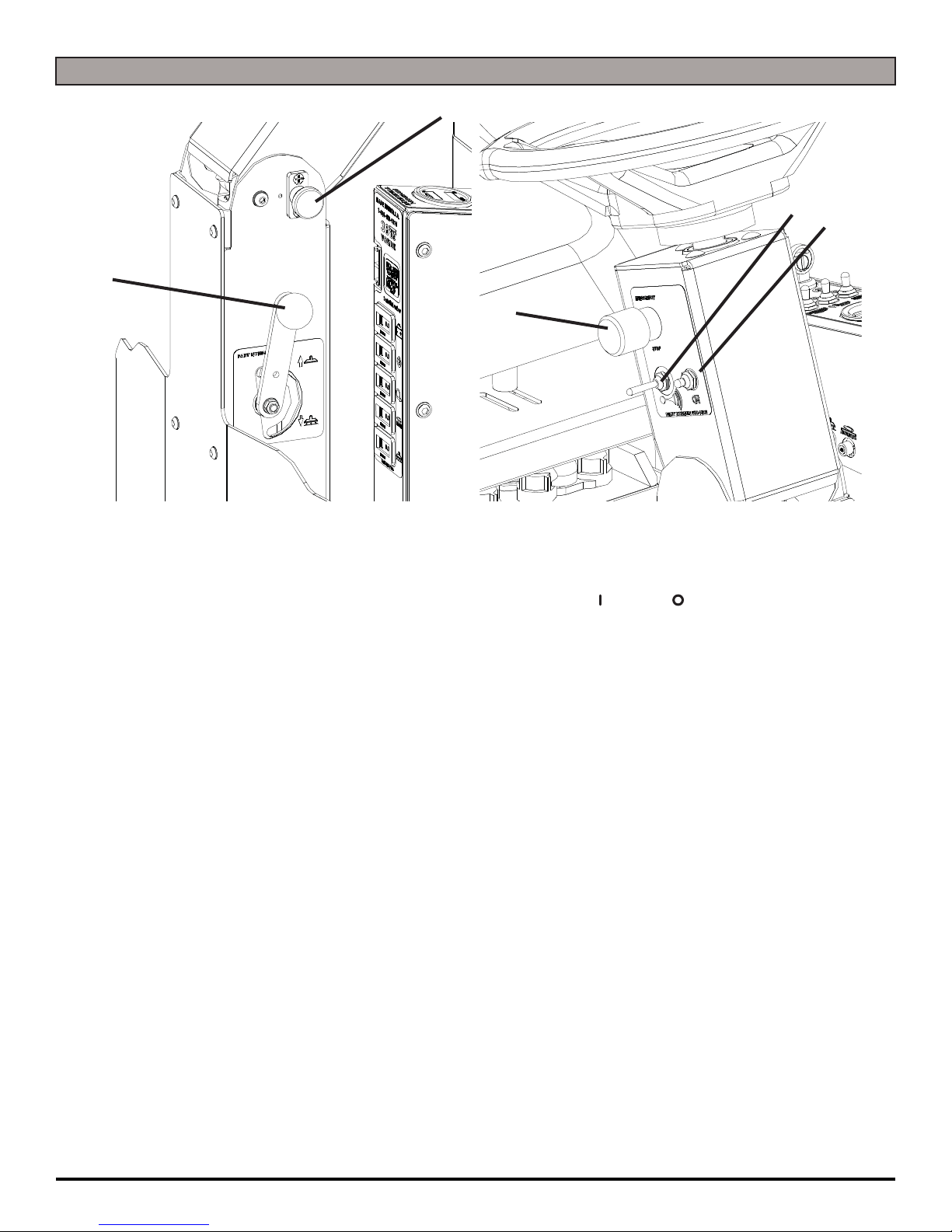
OPERATION CONTROLS
1. ADJUSTABLE STEERING: Four settings for operator comfort and ease of entry
2. HORN: Sounds the horn for warning oncoming traffic
3. HEADLIGHT SWITCH: Turns power of the Headlight ON ( ) / OFF ( )
4. SQUEEGEE LIFT LEVER: Raises and lowers the Squeegee
5. EMERGENCY STOP (OPTIONAL): Allows for complete machine shut down with
1-button push
1
4
5
3
2

RS-OP-EN - 9 -
MACHINE COMPONENTS
1. DRAIN SAVER / RECOVERY TANK LID: Easy visibility Recovery Tank Lid allows viewing of Drain Saver and Recovery Tank
2. RECOVERY TANK: 23 Gallon Capacity - Tip back for easy cleaning
3. TANK LATCHES: Permits draining of the Recovery Tank as well as access to secondary fill point and components in back of
the machine
4. SOLUTION FILL POINT: Fill easily with hose
5. SOLUTION TANK: 22 Gallon Capacity
6. TIE DOWN POINTS: Location for tie down straps during transport (4)
7. SQUEEGEE BLADE: Squeegees water to be recovered by the vacuum hose
8. REAR WHEELS: Cut for complete water control
9. ROLLER BRACKETS: Designed to prevent damage to the deck (Required - Do Not Remove)
10. LOWER FRAME ROLLER BRACKET: Designed to prevent damage to the front of the machine (Required - Do Not Remove)
11. FRONT DRIVE TIRE: Drives and steers the machine
12. LED HEADLIGHTS (OPTIONAL): Helps you see in low light areas and to warn oncoming traffic
13. PARKING BRAKE: Turns the parking brake ON ( ) / OFF ( ) - Never leave in the OFF ( ) position to drive machine
14. POLYURETHANE ROLLERS: Helps prevent damage to machine and objects you may drive near (Walls)
15. METERS: Machine Total Hour Meter & Recharge Counter are standard - Drive, Scrubdeck, and Vacuum are OPTIONAL Meters
16. CHARGER PORT: Plug in your console charger here (36 Volt / 25 amp ONLY)
17. STEERING WHEEL: Steers the main Drive Wheel
18. SEAT: Ergonimic seat with operator comfort in mind
19. VACUUM FLOAT SHUT-OFF: Automatic Vacuum Shut-off if Recovery Tank is Full
20. VACUUM HOSE: Main Vacuum Hose from the Squeegee to the Drain Saver
21. SPRAY JET HOSE (OPTIONAL): Optional Spray Jet hose allows operator to utilize the Solution Tanks cleaning solution in
areas where the machine may not reach to scrub
22. RECOVERY DRAIN HOSE: Allows for controlled draining of the Recovery Tank
23. SOLUTION SIGHT GAUGE & DRAIN HOSE: Shows precise level of cleaning solution in Tank while also used as a Solution
Tank drain hose
24. REAR BUMPER: Offers squeegee system protection from damage
25. SQUEEGEE ROLLERS: Helps protect the Squeegee
26. SQUEEGEE PITCH ADJUSTMENT: Recovers dirty water from the floor to be recovered by Vacuum Hose
27. SIDE WIPERS: Controls water on turns by directing it to the Squeegee
28. ADJUSTABLE SCRUBDECK ARMS: Ensure your Scrubdeck is level with easy adjustable arms (2 levels included)
29. FOOTPEDAL: Use the footpedal for drive power to the front-wheel drive
1
2
3
4
5
6
6
7
8
911
10 12
14
13
15
16
19
20
22
21
23
24
25
17
18
28
29
27
26

- 10 - RS-OP-EN
MACHINE SETUP
UN-CRATING MACHINE:
Carefully check the crate for any signs of damage and that
the batteries are in the unit.
To un-crate the machine, remove banding strips from
around the crate. Take off the top and sides and dispose
properly. Remove brackets from machine wheels.
Remove bolts from pallet, then remove board. Carefully
roll the machine off of the base. Notify the carrier
immediately if concealed damage is discovered.
CONNECTING BATTERIES:
Your machine is equipped with (3×) 12-Volt/ 175 AH WET,
(3×) 12-Volt/ 225 AH WET, or (3×) 12-Volt/ 215 AH AGM
Deep Cycle Batteries which form a 36 Volt system.
(SEE PICTURE BELOW OR BATTERY DISCONNECT
LABEL FOR CORRECT CABLE CONNECTIONS)
1. Turn all switches to the OFF ( ) position and remove
Key.
2. Tip Seat back. Attach all Battery Cables to Terminals
as shown below.
3. Turn ON ( ) main power switch and check the
Battery Charger Meter to ensure correct installation.
Charge Batteries if needed (SEE BATTERY
CHARGING).
NOTICE
Batteries are a possible environmental hazard. Consult
your Battery supplier for safe disposal methods.
NOTICE
Orientation of Batteries is critical for cables to reach.
Ensure proper torque values when installing batteries.
OEM Trojan - 100 in/lbs OEM Full River - 90in/lbs
ATTACHING SQUEEGEE:
1. Turn machine OFF ( ) and remove key.
2. Lower the Squeegee Mounting Plate by lowering the
Squeegee Lift Lever (A) (SEE BELOW).
3. Loosen the two knobs (B) on the Squeegee and slide
them into the slots in the Squeegee Mounting Plate
(SEE BELOW).
4. Tighten the two knobs and connect the Vacuum Hose
(C) from the machine to the Squeegee (SEE BELOW).
5. You may have to adjust the Squeegee Pitch (SEE
ADJUSTING SQUEEGEE ON THE NEXT PAGE)
12V
12V
12V
36 VOLTS
BB
C
AUP
DOWN

RS-OP-EN - 11 -
ADJUSTING SQUEEGEE:
1. Turn machine OFF ( ) and remove key.
2. Turning adjustment knob (A) clockwise (tightening) will
lower tips and raise the center of the Squeegee (SEE
BELOW).
3. This Squeegee is adjusted too far back and will not
pick up on the corners (SEE BELOW).
NOTE: Tips off of the floor.
4. This Squeegee is adjusted too far forward and will not
pick up in the center (SEE BELOW).
NOTE: Center spaced off the floor.
5. This Squeegee is adjusted just right with good
deflection across the entire rear blade (SEE BELOW).
REMOVING SQUEEGEE:
1. Turn machine OFF ( ) and remove key.
2. Raise the Squeegee to the DOWN position by lowering
the Squeegee Lift Lever.
3. Disconnect Vacuum Hose (A) from Squeegee and
loosen both knobs (B) (SEE BELOW).
4. Pull Squeegee assembly backward from the lifting
carrier.
5. Inspect or repair as needed and reinstall.
REPLACING OR ROTATING SQUEEGEE BLADES:
NOTICE
FOR SAFETY: Before leaving or servicing the machine,
stop on a level surface, turn off machine and remove key.
1. Remove the Squeegee Assembly from the machine.
Remove Blade retainer strap and remove Squeegee
Blade.
2. Flip the Squeegee to new edge position or replace.
3. Install Blade on the locating pins of Squeegee
Assembly.
4. Install Squeegee Retainer Strap.
5. Fasten and lock knobs, starting in the center and
moving outwards.
NOTICE
For more information on Squeegee Wipers, Materials,
Sizes, and Replacement - See the COMMON WEAR
PARTS section of the manual in the back of the book.
A
B
B
A

- 12 - RS-OP-EN
INSTALLING DISK PAD DRIVER OR BRUSH:
1. Turn ON ( ) machine power.
2. Raise the Scrubdeck by depressing the Brush switch
to the up and OFF ( ) position (Or Raise with Lever
- OPTIONAL) and turn the machine power back OFF (
). Remove Key.
3. Loosen Star Knobs (A) and remove Shrouds to access
the Scrubdeck (SEE BELOW).
4. Attach Brushes or Pads to Motor Drives. Squeeze the
scissor locking device (B) and lift brush up on to the
motor drive hub (C). Make sure the scissors close and
lock on the brushes (SEE BELOW).
INSTALLING DRIVER PADS:
1. Select the correct Pads that best meet your cleaning
application needs. Consult your local dealer for
assistance.
2. Pad Installation: Attach Pads to Pad Drivers before
connecting drivers to motor hub. Press down on
center clip (D) till it snaps into place (SEE BELOW).
NOTICE
SCRUB BRUSHES / PADS:
There are many different types of brushes available to
cover applications from cleaning heavily soiled floors to
polishing. A Pad Driver is also available to take advan-
tage of the many cleaning pads on the market. Please
refer to the “Common Wear Parts” page to assist in
selecting the proper Brush / Pad for the work at hand.
D
AA
B
C
C
B
C

RS-OP-EN - 13 -
LEVELING DISK DECKS:
NOTICE
All Scrubdeck’s should be level at time of machine
delivery. If machine Scrubdeck is not level - Contact your
Servicing Dealer.
1. Drive machine to a flat level surface and turn machine
OFF ( ).
2. Ensure that Scrubdeck is in full upright position.
Remove Shrouds (A) by loosening Star Knobs (B) and
pulling away from Scrubdeck (SEE BELOW).
3. Turn ON ( ) machine and depress the Brush switch.
Just before the Scrubdeck’s drive hubs touch the
ground, turn machine OFF ( ). Remove key.
4. Loosen the Locking Nut (C) on the Adjustable Deck
Arms. Turn the Hexagonal Arm (D) on each side of the
Scrubdeck to level it (SEE BELOW).
5. Extending the Adjustable Arms raise the front and
lowers the rear of the Scrubdeck. After Scrubdeck has
been leveled (ensure correct pitch backward - if you
have) - retighten Locking Nuts (C).
ADJUST DISK SHROUD WIPERS:
1. For Shroud rubber adjustments, loosen the Nylok Nuts
(E) on the back of the Shrouds (SEE BELOW).
2. To adjust rubber to the desired height, just slide the
curtain up or down in the slits and tighten screws.
3. Reattach the Shroud to the Scrubdeck by sliding back
on and tightening the Star Knobs.
ADJUST DISK SHROUDS:
1. For Shroud adjustments, loosen the Start Knobs (F)
and remove Shroud (SEE BELOW).
2. Spin the Red Shroud Adjustment Knobs (G) up or
down on the Shroud Support Bolt (SEE BELOW).
3. Once adjusted to the proper height, tighten shrouds
back in place.
CD
B
A
B
E
F
D
- 14 - RS-OP-EN
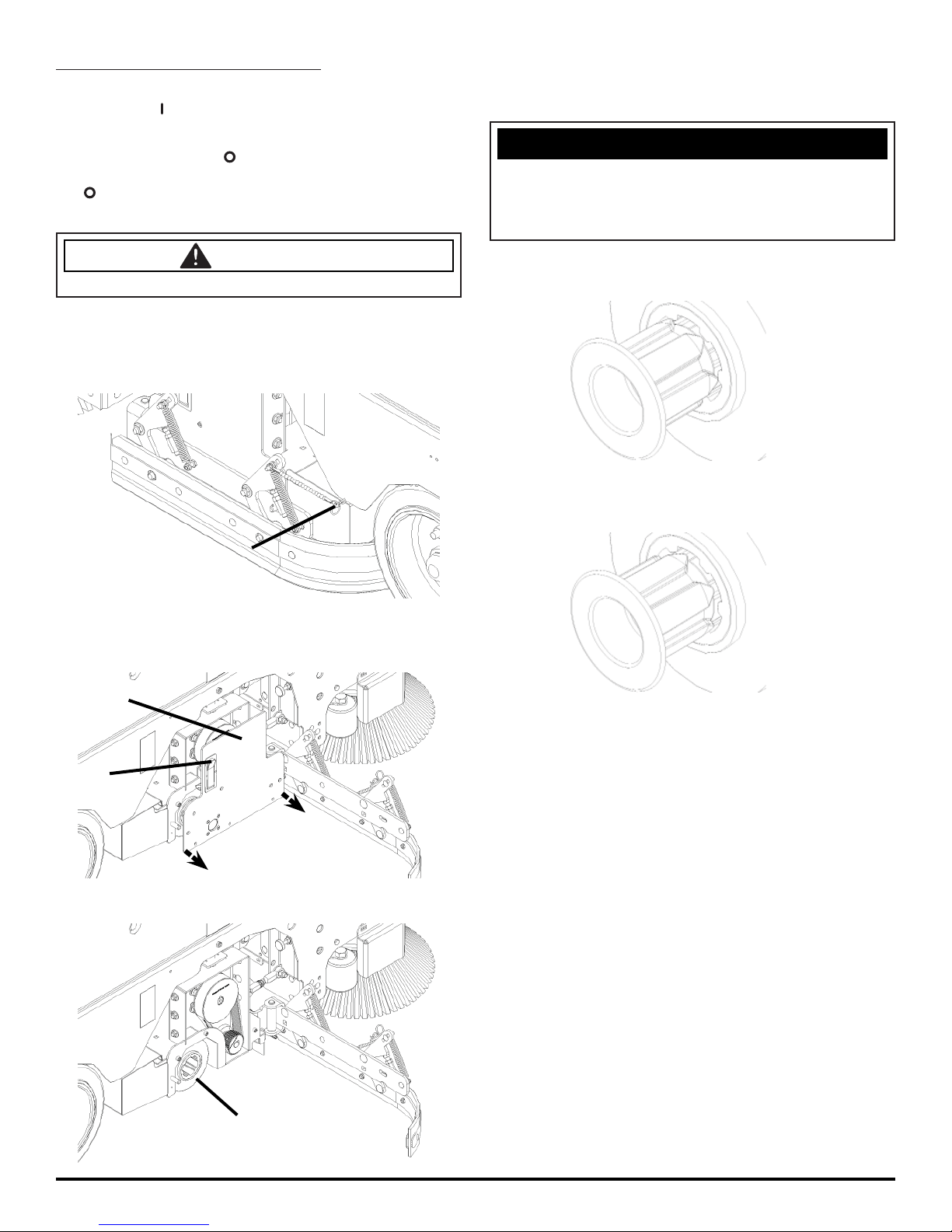
INSTALLING CYLINDRICAL BRUSH:
1. Turn ON ( ) machine power.
2. Raise the Scrubdeck by depressing the Brush switch
to the up and OFF ( ) position (Or Raise with Lever
- OPTIONAL) and turn the machine power back OFF (
). Remove Key.
CAUTION
Disconnect the batteries.
3. Remove Side Wiper pin (A) and open the Wipers out-
ward to allow access to the Cylindrical Door (B) (SEE
BELOW).
4. Press Side Door Latch (C) and pull door off of Scrub-
deck to allow access to the brushes (SEE BELOW).
5. Slide Brush (D) into Brush area and engage onto the
Brush Driver on the opposite side (SEE BELOW).
6. With Brushes engaged, re-attach the Side Door as
well as the Side Wipers.
NOTICE
If the Brushes are not fully engaged with the Drivers,
the Brushes will be damaged. Do NOT force the access
door back on. This usually indicates improper Brush
installation.
7. Brush drivers shown misaligned (SEE BELOW).
8. Brush driver shown properly aligned (SEE BELOW).
A
D
NEW STYLE DRIVER
NEW STYLE DRIVER
B
C

RS-OP-EN - 15 -
LEVELING CYLINDRICAL DECKS:
NOTICE
All Scrubdeck’s should be level at time of machine
delivery. If machine Scrubdeck is not level - Contact your
Servicing Dealer.
1. Drive machine to a flat level surface and turn machine
OFF ( ).
2. Ensure that Scrubdeck is in full upright position and
remove brushes.
3. Turn ON ( ) machine and depress the Brush switch.
Just before the Scrubdeck touches the ground, turn
machine OFF ( ).
4. Loosen the Locking Nut (A) on the Adjustable Deck
Arms. Turn the Hexagonal Arm (B) on each side of the
Scrubdeck to level it. Use the levels built into the deck
(SEE BELOW).
5. Extending the Adjustable Arms raise the front and
lowers the rear of the Scrubdeck. After Scrubdeck has
been leveled - retighten Locking Nuts (A).
ADJUST CYLINDRICAL WIPERS BLADES:
1. For Cylindrical side Wipers, open wipers by releasing
the pin. Loosen Wiper band screws (B) (SEE
BELOW).
2. To adjust Wiper to the desired height, just slide the
Wiper up or down in the slots and tighten the screws.
A
B
FRONT:
BACK:
B

- 16 - RS-OP-EN
INSTALLING EDGE PADS:
1. Turn ON ( ) machine power.
2. Raise the Scrubdeck by depressing the Brush switch
to the UP and OFF ( ) position and turn machine
power back OFF ( ). Remove Key.
3. Select the correct Pads that best meet your cleaning
application. Consult your local dealer for assistance.
4. Remove the EDGE Scrubdeck Shrouds (E) by turning
the Rubber Star knobs (F) and sliding the shroud off
(SEE BELOW).
5. Remove any Pad previously attached to the EDGE
Grip Face by pulling down from the corners (SEE
BELOW).
6. Once Grip Face is clear of any Pads, place pad want-
ed for application centered on the Grip Face (This will
leave a ½’’ overhang on all sides).
7. Press upwards on the Pad to secure it in place (SEE
ABOVE).
8. With Pad attached securely to Grip Face of EDGE
Deck, the machine is ready to use.
NOTICE
NEVER place aggressive Pads (Maroon Prep, Dominator
HD Strip, etc.) directly onto the Grip Face. Always use
Red or Blue Spacer pad to prevent Grip Face damage.
LEVELING EDGE DECKS:
NOTICE
All Scrubdeck’s should be level at time of machine
delivery. If machine Scrubdeck is not level - Contact your
Servicing Dealer.
1. Drive machine to a flat level surface and turn machine
OFF ( ).
2. Ensure that Scrubdeck is in full upright position.
3. Turn ON ( ) machine and depress the brush switch.
Just before the Scrubdeck’s EDGE Pad touches the
ground, turn machine OFF ( ). Remove key.
4. Loosen the Locking Nut (A) on the Adjustable Deck
Arms. Turn the Hexagonal Arm (B) on each side of the
Scrubdeck to level it. Use the Scrubdeck Levels (C)
built into the deck (SEE BELOW).
5. Extending the Adjustable Arms raise the front and
lowers the rear of the Scrubdeck. After Scrubdeck has
been leveled - tighten Locking Nuts (A).
AA
C
B
FF
E

RS-OP-EN - 17 -
ADJUST EDGE SHROUD WIPERS:
1. For Shroud rubber adjustments, loosen the Nylok Nuts
(A) on the back of the Shrouds (SEE BELOW).
2. To adjust rubber to the desired height, just slide the
curtain up or down in the slits and tighten screws.
3. Reattach the Shroud to the Scrubdeck by sliding back
on and tightening the Star Knobs.
ADJUST EDGE SHROUDS:
1. For Shroud adjustments, loosen the Start Knobs (B)
and remove Shroud (C) (SEE BELOW).
2. Spin the Red Shroud Adjustment Knobs (D) up or
down on the Shroud Support Bolt (SEE BELOW).
3. Once adjusted to the proper height, tighten Shrouds
(C) back in place.
BB
C
A
D

- 18- RS-OP-EN
MACHINE OPERATION
PRE-CLEANING CHECKLIST:
Read and understand the complete Operator’s Manual
before operating the machine along with filling out and
sending in a Machine Installation Form.
1. Check Battery Gauge on the Control Panel. Make
sure Batteries are fully charged before using.
2. Check the condition of the Pads or Brushes.
3. Check the condition of the Squeegee Blades.
4. Raise the Scrubdeck and Squeegee before
transporting then transport the machine to the filling
station.
5. Turn the machine OFF ( ). Remove key.
6. Fill the Tank with up to 23 gallons of clean water either
at the fill port (A) (SEE BELOW).
7. Add APPROVED cleaning chemical to the Tank.
Use the proper dilution ratio indicated on the bottle.
Contact us at 1(800)-634-4060 or +001-262-681-3583
if unsure.
NOTICE
The clear tube (Solution Sight Tube) (B) at the front and
rear of the machine indicates the amount of water in the
Tank (SEE BELOW).
DANGER
EXPLOSION RISK! Flammable materials can cause an
explosion or fire. Do NOT use flammable materials in
Tank or pick up.
CAUTION
TO AVOID DAMAGE TO THIS MACHINE:
• Use APPROVED detergents only
• Water temperature must not exceed 130˚F/54˚C
• Do NOT use high-percentage Bleach mixture
OPERATING HINTS:
1. Observe the amount of solution the machine is
dispensing on the floor and adjust to the desired flow.
To increase the solution flow rate, press the Solution
Control Lever forward. To shut the solution OFF ( )
completely, just release the Foot Pedal, or use dash
mounted solution switch ON ( ) / OFF ( ).
2. Keep an eye on the clear Vacuum cover to make sure
that there is not any foamy buildup in the Recovery
Tank. If excess foam begins to develop, stop and drain
tank and pour a recommended foam control solution
into the Recovery Tank. Foam is usually an indication
of excessive soap.
3. Always operate on flat, solid surfaces at lower speeds
when scrubbing around walls and objects. You should
reduce the speed to maintain control when turning.
Don’t operate on ramps or incline.
4. If Squeegee starts to streak, raise and wipe the Blades
with a clean cloth. If the problem continues, check the
Squeegee Hose for clogs and the Squeegee Blades
for wear or damage and rotate if needed. You may
need to pre-sweep before scrubbing. (Only Use OEM
Parts)
5. Change or turn over Brushes / Pads when dirty.
6. Stay clear of objects protruding from the floor such as
sockets, grates, etc, for they will damage the Brushes /
Pads and Squeegee Blades.
7. Always keep an eye on your gauges. They let you
know the status of a particular system at a glance.
If your battery gauge is reading low you must stop
immediately and recharge. Running the Batteries
dead will result in permanent damage to the Batteries.
8. When you run out of solution, raise the Scrubdeck and
continue to Vacuum the remaining water until it is all
consumed. The Solution Sight Tube is used to indicate
the level of detergent remaining in the Tank.
9. When you are ready to stop, raise the Scrubdeck, turn
OFF ( ) the solution switch, raise the Squeegee and
drive the machine back to the charging area. Be sure
to drain both Tanks before storing the machine and
store with key removed and seat in the up position.
A
BB

RS-OP-EN - 19 -
ONE PASS SCRUBBING:
1. Turn ON ( ) machine Key Switch (A).
2. Ensure machine is fully charged before operation
by checking the Battery Gauge (B).
3. Lower the Squeegee by manually lowering
the the Squeegee Lever (C).
4. Turn ON ( ) the Squeegee Vacuum by pressing
the Vacuum Motor Switch [Black] (D).
5. Lower Scrubdeck head to the floor by
pressing the Scrubdeck Toggle Switch
[Yellow] forward on the Control Panel (E).
6. Press the Solution Flow Switch [Blue] (F) to turn ON (
) solution flow. Use the Flow Lever to regulate (J).
7. Begin scrubbing by depressing the Foot Pedal
(G) slowly and then to the speed required.
8. Once the machine begins to move, watch
the Brush Amp Gauge (H) to ensure no
circuits are tripped. Operate in Green.
9. To operate the machine in reverse, simply switch
the Reverse switch [Red] (I) back towards the
rear of the machine. The reverse speed is set
to approximately 50% of the forward speed.
10. To stop the machine, release the Foot Pedal
and the machine will stop automatically (G).
SCRUB ONLY:
1. Turn ON ( ) machine Key Switch (A).
2. Ensure machine is fully charged before operation
by checking the Battery Gauge (B).
3. Lower Scrubdeck head to the floor by
pressing the Scrubdeck Toggle Switch
[Yellow forward on the Control Panel (E).
4. Press the Solution Flow Switch [Blue] (F) to turn on
solution flow. Use the Flow Lever to regulate (J).
5. Begin scrubbing by depressing the Foot Pedal
(G) slowly and then to the speed required.
6. Once the machine begins to move, watch
the Brush Amp Gauge (H) to ensure no
circuits are tripped. Operate in Green.
7. To stop the machine, release the Foot Pedal
and the machine will stop automatically (G).
VACUUM ONLY:
1. Turn ON ( ) machine Key Switch (A).
2. Ensure machine is fully charged before operation
by checking the Battery Gauge (B).
3. Lower the Squeegee by manually lowering
the the Squeegee Lever (C).
4. Turn on the Squeegee Vacuum by pressing
the Vacuum Motor Switch [Yellow] (D).
5. Begin squeegeeing by depressing the Foot Pedal
(G) slowly and then to the speed required.
6. To stop the machine, release the Foot Pedal
and the machine will stop automatically (G).
ADJUST SOLUTION FLOW:
1. Push forward on the Solution Flow Lever (J) to
increase the solution flow and pull backwards on the
toggle to decrease solution flow (SEE BELOW).
H
D
I
F
E
A
B
G
C
J

- 20 - RS-OP-EN
DRAINING RECOVERY TANK:
Always empty Recovery Tank after every shift and when
refilling the Solution Tank. You can refill the Solution Tank
while the Recovery Tank is draining.
1. To drain the Recovery Tank remove Drain Hose (A) by
loosening the Recovery Hose Expansion Plug (B) at
the rear of the Tank (SEE BELOW).
NOTICE
Leave Drain Saver Lid open while draining Tanks. Rinse
thoroughly. Keep Drain Saver Lid open while Charging.
NOTICE
Get Supervisor APPROVAL first and drain at
APPROVED locations only. NEVER off loading docks,
elecated platforms, or stormdrains.
FLUSH RECOVERY TANK:
1. Rinse the Recovery Tank after every use (C). Remove
Tank Lid and pull out the Drain Saver Basket [Yellow]
(D) for access. This will prevent heavy build-up
on the bottom of the tank, foul odors as well as
clogging of your floor drains (SEE BELOW).
2. Remove Drain Hose (A) and open to allow for
drainage of the Recovery Tank (SEE ABOVE).
3. Flush Recovery Tank with water hose.
4. After rinsing, reattach the Drain
Hose (A) (SEE ABOVE).
NOTICE
Keep water off of Control Panel.
CLEAN “DRAIN SAVER”:
With Recovery Lid open and Tank fully drained:
1. Remove Drain Saver Basket (D) from machine
Recovery Tank (E) (SEE BELOW).
2. Rinse Basket with fresh water from the outside while
holding upside down. This will allow for better cleaning.
3. Replace the Drain Saver Basket (D)
into the Recovery Tank (C).
DRAINING SOLUTION TANK:
To drain unwanted cleaning solution from the Solution
Tank, perform the following steps:
(SEE BELOW)
1. Pull the clear Sight Tube/Drain
Hose (A) off barbed fitting.
2. Rinse out Tank and solution flow
system with clean water.
C
D
C
D
A
AB
This manual suits for next models
3
Table of contents
Other Tomcat Blower manuals


