Tomo Audiolabs LISA User manual


Welcome!
Dear Valued Customer,
Thank you for choosing TOMO Audiolabs’ LISA!
This state of the art professional studio equalizer boasts exceptional sonic
possibilities and uncompromisingly high standards.
Assembled from the highest quality discrete components, LISA’s parts are
handpicked specifically for each of their applications. Only ELMA switches, Mundorf
capacitors and our very own hand-wound transformers are used to build each LISA.
Additionally, we do not embed potentiometers into our audio circuitry. We here at
TOMOAudiolabs do this so that each new LISA owner is guaranteed the highest
sonic quality available today!
Numerous listening sessions with our development team and various audio
professionals certified the hope our extensive research and measurements instilled in
us… LISA sounds extraordinary!!
Proving that LISA is not only a masterpiece by technical measures.
Although LISA was designed with the needs of a working audio professional in mind,
its sonic range can help you realize your own audiophile visions as well. If we had
intended for this product to be loved solely by working studio pros we might have
named it the TAL-100 but with all music lovers in mind…we named it LISA.
As a new owner of this marvelous product, we invite you to discover all of the
creative possibilities LISA offers. Be sure to experiment with this wonderful tool and
you will unlock sonic possibilities you never knew existed!!
This user manual will give you the necessary information to start incorporating LISA
in to your daily use. Once you are comfortable with LISA’, we are confident you will
begin applying it in ways that exceed the basic use of other, regular, equalizers.
We wish you endless luck and creativity! - TOMO Audiolabs
3

Table of contents
Table of contents
Welcome!.......................................................................................................................3
Table of contents........................................................................................................... 4
Safety advice and installation notes..............................................................................5
Safety advice.............................................................................................................6
Installation.................................................................................................................7
Rack installation........................................................................................................7
Overview........................................................................................................................8
Overview................................................................................................................... 9
Notes on this manual................................................................................................ 9
Functions.....................................................................................................................10
Input section............................................................................................................ 11
Band 1 – LO BOOST.............................................................................................. 13
Band 2 to 5 – LO, LO MID, HI MID, HI....................................................................15
Band 6 – HI BOOST................................................................................................17
Output section.........................................................................................................18
Applications................................................................................................................. 20
Gain staging............................................................................................................21
Applications.............................................................................................................24
Full reset..................................................................................................................24
Classic equalizer.....................................................................................................25
Simple compression................................................................................................26
Simple expansion....................................................................................................28
Multiband compressor-simulation...........................................................................30
Ducking................................................................................................................... 31
Stereo-link...............................................................................................................33
M/S-technique.........................................................................................................34
M/S-processing....................................................................................................... 35
Appendix......................................................................................................................36
Specifications..........................................................................................................37
Warranty..................................................................................................................38
LISA - Recallsheet.......................................................................................................39
Block diagram..............................................................................................................40
Index............................................................................................................................41

Safety advice and installation notes
5
Safety advice and installation notes
Safety advice
Please read this safety information carefully before proceeding!
Warning! Risk of an electric shock!
•Do not open LISA! The device contains no user-serviceable
parts. Refer all service to qualified personnel.
•Before powering on, verify the local voltage matches the
voltage specified on the power supply unit.
•Do not power unit with damaged power cable.
•Never disconnect or interrupt the ground connection.
•Replace the fuse with the same value and type only.
•Protect the device from all types of liquids, drinks, rain and
moisture.
•Do not use in environments with high humidity.
Use in a humid environment will risk damage and/or the
short-circuiting of LISA!
Caution! Risk of damage and short-circuit!
•Place the device on an even and stable surface or mount it with
all 6 screws to a 19” standard rack.
•Use in well ventilated area. When rack mounted, leave a gap of
at least ½U above and below.
•Do not place the device near any heat sources like radiators or
power amplifiers.
•Do not cover air vents.
•Do not place in direct sun light.
•To avoid condensation damage, leave the unit unconnected for
a longer period after having moved from a cold to warm
environment.
•Do not connect power amplifier outputs to the inputs of the
device.
•Do not apply phantom power to the outputs of the unit.
•Read the notes on balanced and unbalanced connections on
page 7.
•Please read this manual carefully before proceeding!
This device complies with the EU rights and laws on electronic
devices. CE conformity has been certified.
6

Safety advice and installation notes
Installation
LISA features the following connections:
Input channel 1, female XLR, balanced
Input channel 2, female XLR, balanced
Output channel 1, male XLR, unbalanced
Output channel 2, male XLR, unbalanced
All inputs and outputs are transformer coupled and can therefore be used with
unbalanced cabling. Please refer to the following scheme:
pCaution: Using unbalanced connections causes 6 dB level loss.
The use of unbalanced cables will diminish the full dynamic range of the unit.
Therefore, we strongly recommend the use of balanced cabling to achieve noise
cancelation.
LISA can be driven with very high audio levels. Not all equipment can handle high db
levels and will distort or deteriorate signal quality. Significantly low levels can also
degrade audio quality by adding noise. Information regarding optimal operation levels
can be found in the gain staging chapter on page 21.
Make sure to set up the units in your processing chain accordingly.
Rack installation
LISA can be mounted into any standard rack frame. But you´ll need to install the
provided rack ears first. Use all six screws and tighten them firmly!
7
12 2 1
3 3
11
22
33
Input Output
Balanced Unbalanced Balanced Unbalanced
1 = GND
2 = hot (+)
3 = cold (-)

Overview
8

Overview
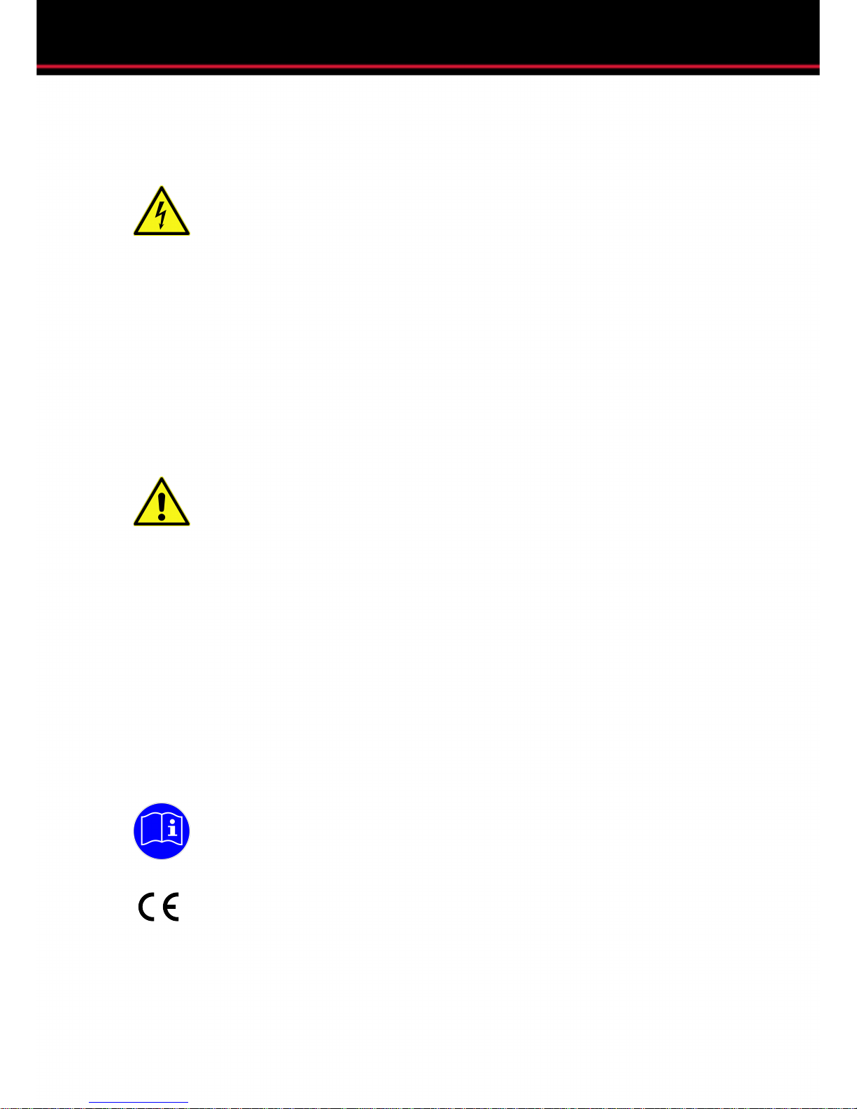
Overview
LISA is a dynamic equalizer with a unique design philosophy, making it different from
any other equalizer you may be familiar with already.
The signal runs through top-notch input amplifier stages equipped with hand-wound
high quality transformers. The signal is then split into six parallel channels that feed
the six independent equalizer bands. After each signal is processed independently,
all six channels are then summed up and amplified. The output stage is also
transformer coupled and gives the user the ability to mix the processed signal with
the unprocessed or dry signal.
Our parallel topology allows parallel processing (two bands at nearly the same
frequency) without the issues of interacting frequency curves. This keeps the
processed signal very transparent, consistent and controllable. The results stay
predictable, helping you to work very quickly and with an experienced touch.
Traditionally designed dynamic equalizers utilize a dynamic processor that is
arranged before or after the filter circuit. Part of what makes the design of LISA’s
dynamic processor so unique is that it is built into the filter circuit. This allows the
user to listen to only the processed signal without any of the dry signal.
Notes on this manual
This manual will help you become comfortable with LISA and all of its features so you
may begin working with it quickly and confidently.
Throughout this manual, the following symbols are used to catch you attention:
iThis symbol refers to a note. Notes help you to understand technical
background informations and interesting applications.
pThis symbols warns of mal-operation. It should help you avoid problems that
degrade audio quality or may even damage the unit or other units of your
processing chain (e.g. loudspeakers).
9

Functions
10
Functions
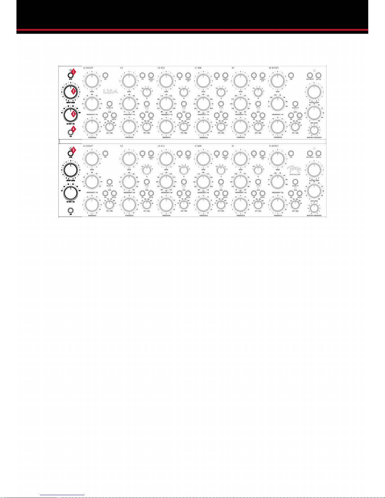
Input section
1MS
i
Activates a MID/SIDE-stereo-mode. In this mode channel 1 processes the MID
signal and channel 2 the SIDE signal.
Note: The MID/SIDE-mode works as a codec. It is not possible to feed LISA a
previously M/S encoded signal and use it as a decoder or the other way around.
However, you can work with previously encoded material and decode it in a third
unit afterwards. Therefore, use normal stereo operation… not M/S-mode!
Additional information on M/S-mode can be found on page 34.
2INPUT GAIN
Controls the amount of input amplification or attenuation on the channel.
The maximum amplification is +6 dB, maximum attenuation is -6 dB.
3LO CUT / Hz
i
Controls the cutoff frequency of the low-cut filter.
Note: When increasing the cutoff frequency, the filter slope becomes less steep.
At 20 Hz it reads about -18 dB, which corresponds to a third order filter. At 180
Hz it reads about -6 dB, which is a first order filter.
11

Functions
4LO CUT ON
Activates the low-cut filter in the channel.
5LINK
i
p
The LINK-switch connects the detector circuits of both channels. This also works
in M/S-mode.
Note: A comprehensive description of this function can be found on page 33.
Attention: When the LINK-function is engaged, the different settings of the
threshold-, ratio- and timing-controls of both channels remain independent.
The LINK-function does not connect setting controls!
12
Functions
Band 1 – LO BOOST
1FILTER BAND ON
Activates the filter band.
2GAIN (Band 1)
i
Controls the amount of level boost in the LO BOOST-band.
Note: Settings between 0 and 6 are stepped in 0.5 dB steps.Above 6 dB the
steps are getting broader. You can find a stepping list in the table shown below,
applicable with 100% dry signal only:
0,5 - 6 0.5 dB per step 12 steps
6,5 - 9 0.6 dB per step 6 steps
9,5 - 10 1 dB per step 2 steps
10,5 1.2 dB per step 1 step
11 - 11,5 1.5 dB per step 2 steps
3FREQUENCY / Hz
i
Controls the filter frequency.
Note: This is the frequency for which the output of the circuit deviates 3 dB from
the passband value. The actual attenuation can start before this point.
13

Functions
4DYNAMICS ON
i
Activates the dynamic processing for the band.
Note: Without the dynamic processing the band works just like any 'normal'
equalizer.A very good specimen of this kind...of course!
5SLOPE HI
Without this function the low-shelving curve is not very steep and has no
resonance overshoot. With this function activated however, the filter curve is
much steeper and shows a negative resonance overshoot. The result is a small
amount of attenuation before the slope starts to amplify.
6RATIO
i
Toggles the processing ratio for the dynamics between a lower and a higher
value. Both settings change depending on all other settings.
Note: The ratio parameter works slightly different to the ratio setting on a
standard compressor you might be familiar with. Try different settings to get to
know the differences.
7ATT / REL
i
Controls the timing settings for the dynamic processing. Attack defines the time
the dynamics section needs to achieve 10 dB of gain reduction. Release defines
the period of time needed to return to unity gain after the signals drop below the
threshold. Six different combinations of fast, medium and slow attack and release
are possible.
Note: The first letter stands for the attack value and the second letter for the
release value.
Example: SM = Slow (Attack) Medium (Release)
F Fast
M Medium
S Slow
8THRESHOLD
p
Defines the level at which dynamic processing is applied to an input signal.
Attention: The absolute value of the individual threshold settings in each band
depends on the master threshold switch in the output section.Additional
information can be found on page 18.
14
Functions
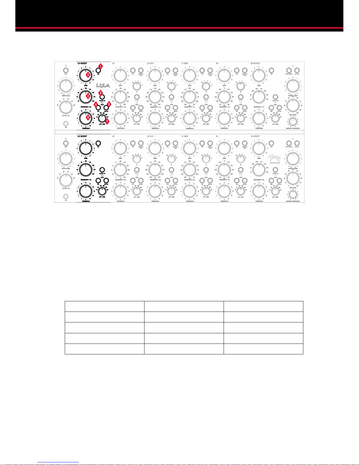
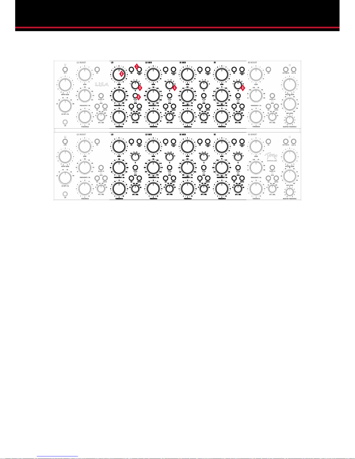
Band 2 to 5 – LO, LO MID, HI MID, HI
1BOOST / CUT
Toggles the gain switch between amplification and attenuation.
Pressed (lit): Amplification
un-pressed (unlit): Attenuation
2GAIN (Band 2 to 5)
i
Controls the amount of amplification or attenuation in each band.
Note: Settings between 0 and 6 are stepped in 0,5 dB steps.Above 6 dB the
steps are getting broader. You can find a stepping list on page 13.
3Q (Band 2)
Q stands for 'quality' and defines the 'broadness' of the filter bell. There are five Q
settings.
The following table shows the different Q-values and their corresponding
bandwidth in musical intervals:
15

Functions
i
Q Bandwidth (rounded) in musical intervals
0,4 3 Octaves
1 1,3 Octaves (4 Thirds)
2 ~ 2 Thirds
4 > 1 Third
6 > Major second
Note: The Q-switch of band 2 has an additional value and can be switched to a
low-shelving mode. When engaged, its slope is classic low-shelf.
4Q (Band 3 and 4)
The Q-switch of band 3 and 4 corresponds in general to its counterpart in band 2
without the shelving setting.
5Q (Band 5)
The Q-switch of band 5 corresponds in general to its counterpart in band 2, but
instead of a low-shelf it features a hi-shelf setting.
6COMP / EXP
i
p
Toggles the filter band´s dynamic processor between compression and
expansion.
Note: Because of LISA’s parallel filter topology, the dynamic processing affects
only the signal parts that are added or attenuated by the filter. It does not affect
the sum signal or the dry signal in any case.
Attention: The function works mirrored in BOOST- and CUT-mode.
Compression is always reducing the maximum amount of equalization.
Expansion is always increasing the adjusted amount of equalization.
16
Functions
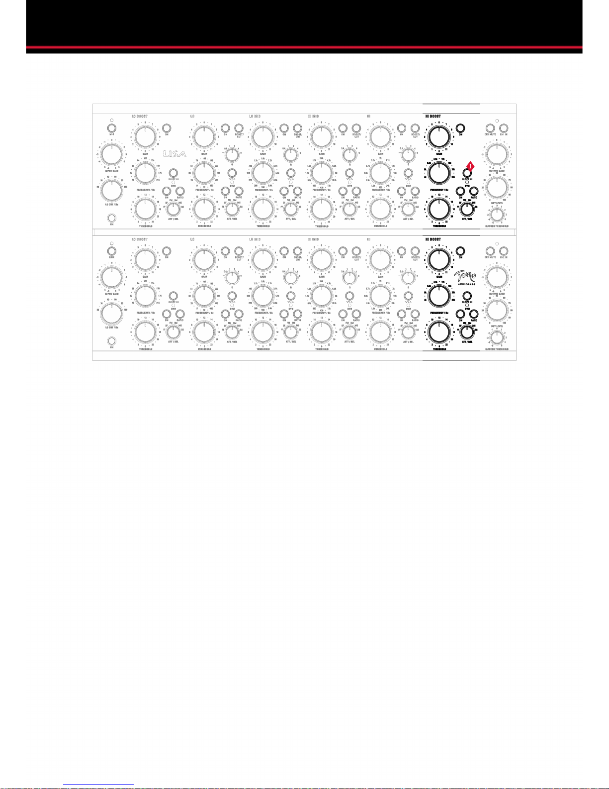
Band 6 – HI BOOST
1SLOPE HI
Without this function the hi-shelving curve is not very steep and has no
resonance overshoot. With this function activated however, the filter curve is
much steeper and shows a negative resonance overshoot. The result is a small
amount of attenuation before the slope starts to amplify.
17

Functions
Output section
1DRY MUTE
Mutes the parallel, direct, dry (unprocessed) signal.
Pressed (lit): dry mute
un-pressed (unlit): dry active
2CH 1 IN
i
Activates channel 1.
Pressed (lit): channel on
un-pressed (unlit): channel bypass
Note: This function works as a hardwire-bypass. Inactivated, the inputs and
outputs are shortcut by relay cards. This also bypasses both the input and output
amplifiers as well as the x-formers. When the power is turned off, LISA falls into
bypass mode.
3OUTPUT GAIN
i
Controls the amount of channel output amplification or attenuation.
The maximum amplification is +6 dB, maximum attenuation is -6 dB.
Note: The output amplifier affects the entire output signal including both the
processed and the unprocessed signals.
18

Functions
4DRY LEVEL
i
Controls the amount of dry signal mixed into the output signal.
Note: This knob only works when DRY MUTE is deactivated.
5MASTER THRESHOLD
i
Controls the offset of the threshold values of each band in one channel.
The offset reads about 6 dB per step.
Negative amounts raise all thresholds, which result in less processing.
Positive amounts lower the thresholds, which result in more processing.
Note: The proportions between the thresholds of the individual bands remain
untouched.
The MASTER THRESHOLD function can be especially useful when the input
gain setting must be changed but all threshold settings are already adjusted.
6CH 2 IN
i
Activates channel 2.
Pressed (lit): channel on
un-pressed (unlit): channel bypass
Note: This function works as a hardwire-bypass. Inactivated, the inputs and
outputs are shortcut by relay cards. This also bypasses both the input and output
amplifiers as well as the x-formers. When the power is turned off, LISA falls into
bypass mode.
19

Applications
20
Table of contents


