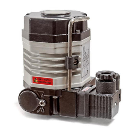
Tomoe T-DYNAMO 7E User manual

R
INSTRUCTION MANUAL
Compact, Lightweight, High-output Pneumatic Actuator
Before placing an order
* "Before placing an order" has been described since 25 May, 2005.
FOR YOUR SAFE USAGE
1.PRODUCT FEATURES
1-1 Product features
1-2 Operating principle
1-3 Type description
1-4 Standard specifications
2.PRECAUTIONS FOR USE
2-1 Safety measures
2-2 Transportation and storage
2-3 Installation and working environment
2-4 Use and adjustment
2-5 Maintenance
3.STRUCTURE
3-1
Expanded view (Double-acting type cylinder)
3-2
Expanded view (Single-acting type cylinder)
3-3 Output torque curves
3-4 Air consumption
4.CYLINDER SYSTEM CONFIGURATION
4-1 System configuration
4-2 Speed controller
4-3 Adjustment of valve position
4-4 Manual operation procedure
4-5 Solenoid valve
4-6 Limit switch
5.CYLINDER MAINTENANCE
5-1 Disassembly procedure
5-2
Single-acting type cylinder side cover disassembly procedure
5-3 Assembly procedure
5-4
Single-acting type cylinder side cover assembly procedure
5-5 Troubleshooting
1
2
2
2
3
3
4
4
4
5
7
8
10
10
11
12
12
13
13
14
15
17
19
21
22
22
24
25
29
30
Page
CONTENTS
Warranty Period
The warranty period of the delivered product should be eighteen (18) months after shipment
from our factory or one (1) year after the date of starting trial runs, whichever comes first.
Scope of Warranty and Indemnity
If any damage or problem should occur during the foregoing warranty period due to our fault,
Tomoe Valve will replace or repair any defective part of the product free of charge at the
place where the product was purchased or where it was delivered (limited to Japan).
However, warranty is not applicable if the causes of defect should result from the following:
(1) The failure was caused by inappropriate conditions, environment, handling or use
methods, etc. which are not specified in the catalog, specifications or other relevant
documents that had been made and entered into between the customer and Tomoe
Valve.
(2) The failure was caused by the product other than the delivered Tomoe's product.
(3)
The failure was caused by modifications or repairs by a party other than Tomoe Valve.
(4) The failure was caused by use under the condition that had not been given as required
specifications of valves, etc., or by a problem that was not foreseen from the specified
conditions.
(5) The failure was caused by significant wear and tear of the seat ring, the gland packing,
etc.
(6) The failure was caused by poor application of consumables, such as lubricant.
(7) The failure was caused by inappropriate maintenance or inspection under highly
frequent valve operation.
(8) The failure was caused by power source or air supply.
(9) The failure was caused by foreign substances, such as dust, that entered and clogged in
the product.
(
10
) The failure was caused by inappropriate storage of the product, such as open air
storage.
(
11
)
The failure was caused by fire, flood, earthquakes, fall of rocks, and other acts of God.
(
12
) The failure was caused by other reasons which are not our responsibility.
In addition, the forgoing warranty is only applicable to the product itself and excludes com-
pensation of any other indirect or consequential damage.
Charged Repair Service and Supply of Discontinued Parts
Products are subject to discontinuation or modification without notice. For products
that are no longer manufactured or sold, repair or overhaul of the products may not be
available after 5 years since discontinuation. In addition, supply of the parts or spare
parts of the products may not be available.
■CONTACT
New (7E/7F/7G)
2018.10.31-PhCat.No.EM1045-③
●Head Office
3-11-11 Shinmachi, Nishi-ku, Osaka 550-0013, Japan
Global Sales Operations
www.tomoevalve.com
No. 317, Kamol Sukosol Building, Unit B, 12th Floor, Silom Road, Silom Sub-district, Bangrak District, Bangkok 10500, Thailand
TOMOE VALVE (THAILAND) CO., LTD.
15700 International Plaza Drive Suite150, Houston TX, 77032 USA
Telephone: +1-281-358-7571 Telefax: +1-281-358-7861
TOMOE USA Inc.
Room 1102, Building A, St.NOAH Plaza, No.1759 Jinshajiang Road, Putuo district, Shanghai. 200333, China
TOMOE VALVE INDUSTRY (NANTONG) CO., LTD.
http://www.tomoe.sh.cn
BlockF2 Latrade Industrial Park, JI. Sei Binti Tanjung Uncang, Batam 29422 Indonesia
PT. TOMOE VALVE BATAM
http://www.tomoe-batam.com
No 2, Toh Guan Road East, #02-02, Singapore 608837
TOMOE VALVE ASIA PACIFIC PTE. LTD.
www.tomoe.com.sg
Clearwater Road, Queensway Meadows Industrial Estate,
Newport, South Wales NP19 4ST, United Kingdom
www.tomoeeurope.co.uk
TOMOE VALVE LIMITED

1
2
The instructions hereunder are for long-lasting service of T-DYNAMO (hereinafter "this
product") without loss or hazard.
Please read this manual thoroughly before use in order to ensure correct use of the product.
Separate information for the safety precautions for handling valves should also be observed.
a
a
b
b
Port A
Port B
Cover⑥Case①
Parallel pin㉜
Piston packing㉔ Cover⑦
Piston⑤
Piston⑤
Shaft②
Yoke③
Parallel pin㉜
Spring㊷
Piston⑤
Shaft②Cover⑥
Piston⑤
Spring㊷
Port C
PortBb
b
a
a
Cover⑦Yoke③
FOR YOUR SAFE USAGE
The following instructions should always be followed.
WARNING
This mark indicates "possibility of death or serious injury".
This mark indicates items that "you must not do".
This mark indicates items "you must do".
CAUTION
■We will indicate the following marks for your attention. (The following are examples of marks.)
Introduction
●Be sure to read this instruction manual before transportation, storage, piping installation, operation, and mainte-
nance and inspection.
●This instruction manual does not describe all the assumed conditions on transportation, storage, piping installa-
tion, operation, maintenance and inspection of this product. If there are any questions, please contact our sales
department.
●Reference values and limit values for operation, maintenance, and inspection specified in this instruction manual
have been determined in consideration of maintenance management of this product. This product should be used
within the range of the reference values and the limit values.
●This product should be used by connecting only to a valve with an opening/closing angle of 90 degrees or less.
●Be sure to store this instruction manual in a readily accessible place for future reference after installation and
operation start. If a staff in charge is changed, information on the storage place of the instruction manual and
operation should be communicated to the next staff.
●If dents or scratches are made on impact, stop using the product for safety and replace the product.
*Details of this instruction manual are subject to change without notice.
1-1 Product features
■Double-acting type cylinder
(1) The cylinder space which is enclosed by the case ①and the
covers ⑥and ⑦is divided into airtight chambers ⓐand ⓑ
by the pistons ⑤and the piston packing ㉔.
(2) The shaft
②
penetrates the chamber
ⓑ
of the case. The yoke
③
is
fitted in the hole across the shaft in such a way that it allows it to slide
in the hole. The top of the yoke is connected with the parallel pins
㉜
so it rotates in accordance with the movement of the pistons.
(3) The compressed air enters chamber ⓐthrough port A and
pushes the pistons. The air in chamber ⓑis exhausted through
port B as the pistons move due to a pressure difference
between the two chambers. Integrated with these pistons, the
parallel pins ㉜also move and torque in the shaft is generated.
■Single-acting type cylinder
(1) The cylinder space which is enclosed by the case ①and the
covers ⑥and ⑦is divided into airtight chambers ⓐand ⓑ
by the pistons ⑤and the piston packing ㉔.
(2) The shaft ②penetrates the chamber ⓑof the case. The yoke
③is fitted in the hole across the shaft in such a way that it
allows it to slide in the hole. The top of the yoke is connected
with the parallel pins ㉜so it rotates in accordance with the
movement of the pistons.
(3) The compressed air enters chamber ⓑthrough port B and
pushes the pistons. The air in chamber ⓐis exhausted
through port C as the pistons ⑤move and the spring ㊷is
squeezed due to a pressure difference between the two
chambers. Integrated with these pistons ⑤, the parallel pins
㉜also move and torque in the shaft is generated.
(4) When air supply to Port B is stopped, the pistons are pushed
back due to the force of the spring ㊷and torque in the shaft
is generated.
1-2 Operating principle
This product is a pneumatic rotary actuator driven by pneumatic pressure of 0.4 to 0.7 MPa for the purpose of
actuating a 90˚ butterfly valve. The case is of aluminum alloy which is fabricated by means of extrusion. This manu-
facturing method enables the cylinder to be light weight, compact in design and highly accurate. The attachment
installation member complies with the NAMUR standard. NAMUR standard attachment parts can be installed directly.
1. PRODUCT FEATURES
Piston movement
Air flow
Double-acting type cylinder Single-acting type cylinder
■We will indicate level of danger or damage caused by neglecting these cautions as the
following:
This mark indicates "possibility of injury to personnel or physical
damage only".

WARNING
CAUTION
CAUTION
��
2-1 Safety measures
2.1.1 Handling of this product
This product should be handled by knowledgeable and experienced technicians only.
Compressed air, etc. is hazardous if wrongly handled. Assembly, operation, maintenance of a machine
or a unit utilizing compressed air should be handled by technicians who have read the instruction
manual (hereinafter "this manual") thoroughly and understand the contents completely.
2.1.2 Safety check
Handling or dismantling of the machine or the unit must not be carried out until safety
precautions are ensured.
The machine should only be dismantled after checking the following items to ensure safety.
①Safety precautions for this product, such as preventions against falling of parts, material or other
accidental happenings, have been taken.
②The surface temperature of this product is a temperature where the surface can be touched.
③Supply air, etc. that are power sources and compressed air in the air piping system have been
removed.
④No fluid flows in the pipelines.
⑤The power of the system has been shut off.
Before restarting of the unit, check the following items.
①This product is fixed to a valve securely.
②There is no failure or damage on the appearance of this product, or loss of parts.
③Tools have not been left on this product.
④Nothing hinders operation of this product (operation of the cylinder, opening/closing of the valve).
⑤There is no leakage of electrical and pneumatic signals.
⑥There is no leakage of compressed air, etc.
2.1.3 Fail-safe design
When the unit is used for the point where fail-safe design is required, adopt a method where the
system responds in a way that will cause no harm using a single-acting type cylinder (spring back
cylinder), a lock-up valve, etc. in case of loss of all or a part of power that controls the machine.
2.1.4 Water hammer
Design should be performed in consideration of water hammer. Water hammer may occur even
within the opening and closing times in the range of the product specifications, depending on the
pipeline conditions or valve operating conditions.
2-2 Transportation and storage
2.2.1 Mass
Products with large mass (approx. 20 kg) should be transported using equipment or a machine, not
by man power alone. See the catalog issued by our company, product drawings, etc. for the mass
of this product. Qualified personnel should perform work with a forklift or a crane, or slinging work in
accordance with laws and regulations, and safety provisions of business establishments.
2.2.2 Falling
When this product is unloaded or transversely held, it should be held appropriately to prevent it from
falling and being damaged.
2.2.3 Dust-proofing, water-proofing
The plug (tentative seal plug) connected to the piping connection should not be removed until
pneumatic piping work is performed. If dust-proofing and water-proofing measures are not taken,
dirt, dust, rainwater, etc. will infiltrate this product, causing defective operation. If the plug is lost,
take protective measures using a cover or protection tape instead. For single-acting type cylinders,
orient the elbow of the exhaust port downwards to prevent infiltration of dirt, dust, rainwater, etc.
2. PRECAUTIONS FOR USE
3
4
Type
Torque (N·m)
(When supply pressure
is 0.4MPa and
rotation angle is 0°)
Supply air pressure
condition/temperature
Air supply
pressure (MPa)
Body shell max (MPa)
Air connection (Rc)
Rotating angle
Ambient temperature
Travel time (sec)
With speed controller *
Dehumidified air / -10°C ~ +60°C
0.4 ~ 0.7MPa
1.05MPa
Rc (PT)1/4
90°
-10°C ~ +60°C
T35
35
T85
85
T200
200
T380
380
T750
750
T85S
30
T200S
65
T380S
116
T750S
240
1~15 2~15 3~15 7~20 12~25 2~15 6~15 8~20 15~25
Double-acting type cylinder (7E) Single-acting type cylinder(7F/7G)
1-3 Type description
1-4 Standard specifications
Double-acting type cylinder (7E) Single-acting type cylinder (7F/7G)
T85
① ② T85S
① ② ③
* The output torque of single-acting type differs from that of double-acting type. Please refer to 1-4 Standard
specifications.
*
The opening and closing times are the times in the case of a single unit of a cylinder with a standard speed
controller (SP-K017-Z03-006) and a solenoid valve (PCS2408-NB-100MC) when the air supply pressure is 0.4
MPa.
The opening and closing times depend on pneumatic piping system, etc.
①Identification of this product
②Identification of type
③Operation type: Spring return
①Identification of this product
②Output torque (*)

WARNING
CAUTION
2.3.5 Vibration and impact at installation location
The following measures should be taken if there is vibration or impact at the location where this
product is installed.
①When this product is used with the following conditions, after checking vibration or impact
conditions (particularly acceleration value, etc.), consult with our sales department.
1) Location where excessive vibration or impact is exerted
2) Location where vibration or impact is exerted continuously
②Installation sections and connecting sections, etc. of this product should be locked to fix and fasten
securely. Particularly, when the product is used under highly frequent opening/closing conditions,
fastening should be performed with a significant margin in consideration of fatigue resistance.
③Vibration isolation measures should be taken to reduce vibration or impact on the machine.
Pipelines should be fixed with supports, or vibration isolation material should be installed.
④Joints should be checked periodically against looseness and deformation. In case of abnormal
conditions, bolts should be retightened or parts should be replaced. Coming off of fastening
bolts may cause falling off or rotation in an unexpected direction of this product.
2.3.6 Design of a connection part between a valve and this product
The following items should be checked when a connection part between a valve and this product is
designed.
①Thrust load and lateral load should not be applied to the output shaft of this product.
②At independent retainer should be installed to the valve stem of the valve to prevent travel in
the shaft direction. If the output shaft of this product is used as a retainer for the valve stem of
the valve, the valve stem may protrude due to fluid pressure when this product is removed.
③The dimension to fit the output shaft of this product and the valve stem of the valve should be
secured sufficiently. Please refer to separate dimensional outline drawings for appropriate fit
dimension. If the fit dimension is insufficient, strength at fitting section may become insufficient,
resulting in damage.
2.3.7 Precautions at pneumatic piping
Pneumatic pipelines should be connected to this product while paying attention to the following
items. If dents or scratches are made on impact, to ensure safety stop using the product and
replace the product.
①
This product, attachments, and pneumatic pipelines should be kept free from external force or shock.
Rough handling may cause deformation of the output shaft, or air leakage due to damage of O-rings.
②Standing on this product should be avoided at connecting pipelines. This product should not
be inserted by hitting the product.
③Before connecting pipelines, pipeline members and fittings, particularly the air filter
secondary-side should be thoroughly cleaned by air blowing (flushing) or other suitable
cleaning method to remove cutting dust, oils and other debris.
④When the pipelines and fittings are screwed into the unit, care must be taken to avoid infiltra-
tion of any cutting dust or sealant into this product.
⑤When the fittings are screwed into the unit, excessive force may cause damage. After the
joints are screwed in lightly, the joints should be retightened in a 1/4 turn as a guide. The
reference value of the tightening torque is approx. 10 – 14 Nm.
⑥In order to prevent infiltration of foreign substances into the piping air ports and vents, plugs
(tentative seal plugs) have been installed before shipping. Remove all of them before using.
2.3.8 Precautions for attachments
The following items should be checked on the attachments of this product.
①The speed controller that is standard equipment of this product is fully opened when shipped.
Before using, please turn it in the closing direction (clockwise) and adjust the opening and closing
times. Please refer to 4-2 Speed controller for operation procedure of the speed controller.
②The rotation speed should be adjusted with the speed controller. No speed adjustment should
be attempted by means of a pressure reducing valve. High speed opening/closing may cause
water hammer of the valve. Therefore, care should be taken in speed adjustment.
③If the opening and closing times of this product influence system operation timing, leave a
sufficient margin for the opening and closing times. The opening and closing times may
change due to conditions, such as fluid pressure and temperature.
④In order to prevent damage during transportation, parts, such as resin silencers, may be packed
without being installed. Please install them before operation after completing valve installation.
2.2.4 Storage
This product should be stored as follows to prevent contamination, discoloration, and material
deterioration.
①This product should be stored in a place with no dust or water droplet while avoiding direct
sunlight, high temperatures and humidity.
②This product should be stored in a packed state or with equivalent protective measures.
③When this product which has been stored for more than 1 year is used, the operational status
of the product should be checked. If any abnormal condition is found, overhaul, and replace-
ment of deformed or degraded parts should be performed.
2-3 Installation and working environment
2.3.1 Obtaining space for installation location
For installation location, work space should be obtained around this product. If work space cannot
be obtained, parts may not be removed at maintenance.
2.3.2 Installation location and working environment
In the following installation locations or working environments, special actions, such as compliance with
laws and regulations, may be required in some cases as well as functional conformance to specifications. If
there are any questions, please contact our sales department at planning stage.
①Special working environments which are not described in the specifications.
②In the case where substantial damage to human beings, assets, environments, etc. is
predicted if the product fails.
e.g.: Facilities related to High Pressure Gas Safety Act, facilities related to Industrial Safety
and Health Act, Nuclear power related facilities, vehicles, medical facilities, etc.
2.3.3 Atmosphere of installation location
The following measures should be taken depending on the atmosphere of the location where this
product is installed.
①Locations which are exposed to gas containing salt, corrosive gas, chemical solution, organic
solvent, steam, etc. should be avoided. For some kinds of atmosphere, anti-corrosive mea-
sures can be taken. Please consult with our sales department.
②If there is a possibility that this product is exposed to direct radiant heat or chemicals, the
product and attachments should be protected with a cover, etc.
③When a single-acting type cylinder is used outdoors or in a location where the unit is exposed
to water, the elbow of the exhaust port should be oriented downwards to prevent infiltration of
dirt, dust, rainwater, etc.
④This product should not be submerged.
2.3.4 Temperature of installation location
The following measures should be taken depending on the temperature of the location where this
product is installed.
Using the product out of the specified temperature range causes thermal degradation or hardening of
O-rings, thermal expansion of parts, defective operation due to difference of thermal shrinkage, etc.
①The ambient temperature of the installation location should be based on the specifications.
②The supplied compressed air, etc. should be based on the specifications.
③If the product is exposed to direct sunlight, the working temperatures of this product and
attachments should not exceed the upper limit.
④This product should be kept away from heat sources, and installed in a location where the
temperature is within the specified temperature range. Particularly, ambient temperature may
exceed the specified temperature range near a motor, an air compressor, etc.
⑤The attachments should be used within the appropriate temperature range of the attachments.
5
6

WARNING
CAUTION
2.4.6 Modification
This product should not be modified. Deterioration of durability or breakage of this product may pose a
danger to the environment.
2.4.7 External manual operation
Care must be taken for the following items at external manual operation.
①For only double-acting type cylinders, a valve can be opened or closed manually by turning the
output shaft of the actuator with a spanner after the supply and exhaust pressures become the
same with the bypass valve (except Type T750).
Please note that, when the bypass valve is opened, the valve opening changes due to fluid
pressure.(Please refer to 4-4 Manual operation procedure for how to use the bypass valve.)
②The manual operation torque may change abruptly depending on the valve opening, and you
may lose balance, resulting in falling. Manual operation should be performed while securing
safety with scaffolding, space, etc.
③In the case of Type T750, large operating force is required and operation with small tools is
dangerous. Thus external manual operation should not be performed with a spanner or a
monkey wrench. Please use a manual gear for the operation.
④
For single-acting type cylinders, manual opening/closing operation should not be performed with a
spanner, a monkey wrench, or a manual lever for double-acting type cylinders (hereinafter "dedicated
lever"). If the output shaft is turned with a spanner, a monkey wrench, or the dedicated lever, the shaft is
rotated backwards by the spring force, which is dangerous. Please use the manual screw handle.
⑤
The spanner, monkey wrench, or special lever used at manual operation must be removed at comple-
tion of the operation. In case of automatic operation with them mounted, the spanner, monkey wrench,
or special lever may come off and fall out, which may cause personal injuries or machine damage.
⑥In the case of a unit with a manual gear, before switching operation to automatic operation
after manual operation, check that the manual gear is at the position of automatic operation
and the bypass valve is closed. (They are not returned automatically.)
2.4.8 Others
①If air supply is stopped for a long period of time after compressed air, etc. is supplied to this
product, the valve opening position may not be kept.
②When operation is restarted after a long downtime (5 days or more), operation time may be
longer than usual due to increase in grease viscosity or valve resistance, etc.
2.5.1 Residual pressure
Even after supply of compressed air, etc. to this product is stopped, compressed air may gush out
or unexpected operation may occur due to residual pressure in the cylinder. Installation work and
maintenance should be performed after removing residual pressure from the cylinder.
2.5.2 Maintenance and inspection of this product
Maintenance and inspection should be performed according to 5-1 Disassembly procedure in this
manual. At maintenance and inspection of this product, inspection should be made while paying
attention to the following items.
①For single-acting type cylinders, the cover may fall out due to the force of the internal spring
even if compressed air, etc. is not supplied, which may cause injury or damage.
②Bolts should not be loosened, while compressed air, etc. are supplied, or this product or the
valve can be operated. Compressed air may gush out or unexpected operation may occur.
2.5.3 Daily check
Daily check including the following items on this product should be performed.
①Water accumulated in the filter regulator etc. should be drained from the drain exhaust port.
②During operation of this product, visual check and noise check should be performed from a
safe location. Inspection should be made on defective appearance, such as looseness of the
bolts, abnormal noise during operation, rattling, air leakage to the outside, air leakage from
exhaust vents and piping joints, etc.
③If compressed air, etc. is supplied even if operation of this product is stopped, inspection
should be made on looseness of the bolts, air leakage to the outside, and air leakage from
exhaust vents and piping joints.
2-5 Maintenance
2.4.1 Operating air
The following items should be checked on operating air of this product.
1) Use clean operating air to operate this product.
2) It should be checked that compressed air, etc. supplied to this product should be within the range
between 0.4 MPa and 0.7 MPa.
3) Supplied air should be filtered with an air filter etc. to remove foreign substances. The filter should
be of 40 µm or finer mesh.
4) Supplied air should be dehumidified with an air dryer, etc. (dew-point temperature at atmospheric
barometric pressure is -15°C or lower) to remove moisture from the air.
5) Compressed air, etc. should be kept free from the following to prevent defective or abnormal
operation of the unit.
• Chemicals, synthetic oils with organic solvent base, corrosive gas, deteriorated compressor oil
6) Attachments (solenoid valve, regulator, filter, pneumatic line size, joint, etc.) should be selected with
consideration of pressure loss so that the air pressure is within the range of the specified pressure
at the air inlet port of this product. Otherwise the opening and closing times may slow down.
7) In case of lack of supply of compressed air, etc. to this product, intermittent operation of the pistons
occur, or the valve is stuck. Care should be taken to avoid lack of air supply amount and air supply
pressure. When the pneumatic pipeline is 5 m or more, take measures, such as use of a large-
diameter pipeline, etc.
8) Cylinder capacity of a pneumatic actuator varies largely subject to type of actuator. Please select
the suitable air compressor capacity. Please refer to 3-4 Air consumption.
2.4.2 Supply pressure adjustment
Piping should be designed so that suitable compressed air amount and pressure are supplied to this product.
Insufficient air supply amount or air supply pressure may affect opening/closing operation of the valve.
In cases of pneumatic devices in which the pneumatic pipeline inlet of this product or the end of the plant
pipeline is connected with a long pipeline, air supply amount and air supply pressure may be insufficient
for this product due to loss at pipelines. An auxiliary air tank should be installed, etc. as needed.
2.4.3 Operation check
When this product is purchased separately, operation check should be performed with the following
procedure.
①It should be checked that there is no flaw in the appearance, damage or loss of parts.
②This product should be checked separately for proper operation.
③After connecting to the valve, adjust the valve opening. (Please refer to 4-3 Adjustment of valve
position for details.)
④Valve opening/closing operation should be checked.
When this product integrated with a valve (hereinafter "finished product") is purchased, operation check
should be performed with the following procedure.
①It should be checked that there is no flaw in the appearance, damage or loss of parts.
②It should be checked that pipelines for compressed air and electric signals are connected.
③It should be checked that there is no air leakage from pipeline connecting sections and this product.
④Valve opening/closing operation should be checked.
2.4.4 Valve opening adjustment
Valve opening should be adjusted while paying attention to the following points.
①When finished products are purchased, the stopper bolts at the closing side should not be
loosened. If the stopper bolts at the closing side are loosened, the valve full closing position
changes, and valve seat leakage may occur.
②Before adjustment, compressed air, etc. should be discharged from this product. If there is any
residual pressure due to compressed air, the stopper bolts may fall out.
③After adjustment, it should be checked that there is no air leakage from the stopper bolts.
2.4.5 Opening and closing time
If the opening and closing time is shorter than the minimum time of the product specifications, durability
of this product may be deteriorated.
2-4 Use and adjustment
CAUTION
CAUTION
CAUTION
7
8

CAUTION
T35 only
T750 only
2.5.4 Periodical inspection
Periodical inspection including the following items on this product should be performed.
①After opening and closing 50,000 times or 1 year of use, whichever one is earlier, inspection
should be made on looseness of each bolt and air leakage. The bolts should be retightened
and consumables should be replaced as needed.
②From the second year, the above-mentioned inspection should be made every year.
2.5.5 Removal and installation
①Before this product is removed from the valve power and compressed air, etc. must be shut off
and residual pressure must be removed from the machine and pipelines completely. Otherwise
compressed air may gush out or unexpected operation may occur.
②When two or more valves and the products are removed, numbers or symbols shall be put on
the valves and the products to identify the corresponding valve and product. Mistaken installa-
tion may cause failure or defective operation of the unit.
③Match marks should be made on the top plates of this product and the valve to indicate the
installation orientation of this product. Mistaken installation orientation may cause defective
operation.
④Loosen the hexagon bolts which fix this product on the valve to remove this product. If joints
are included in the valve, please be careful not to lose them. Loss of joints may cause defec-
tive operation.
⑤When this product is removed, the valve full closing position may be changed. Valve seat
leakage should be checked. In case of leakage, the full closing position should be adjusted.
Please refer to 4-3 Adjustment of valve position for adjustment of the full closing position.
⑥At installation, it should be checked that opening of the valve and the opening of this product
are the same. If the openings are not the same, opening and closing operation is performed in
the reverse way.
2.5.6 Replacement of consumable parts
The product should be disassembled and assembled in a clean location which is free from dust and dirt.
Please refer to 5-1 Disassembly procedure for replacement procedure of consumables. Consum-
able parts of single-acting type cylinders should be replaced according to 5-2 Single-acting type
cylinder side cover disassembly procedure.
2.5.7 Lubricant
Grease has been applied to the sliding elements of this product. Lubrication by supply air is not
required. However, it is recommended to apply grease after opening and closing 50,000 times or 1
year of use, whichever one is earlier.
2.5.8 Safety check
During maintenance and inspection, all workers should be informed of the following conditions:
power and compressed air, etc. are shut off, residual pressure is discharged completely, or power
and compressed air, etc. are supplied again.
2.5.9 Disposal
This product should be disposed while paying attention to the following items.
①This product should not be disposed of by incineration. There is a risk of toxic gas generation
and bursting. Therefore please dispose of it as general industrial waste. The product does not
contain materials which cannot be disposed of as general industrial waste.
②When this product is disposed after sorting, materials should be classified according to the
materials specified on drawings.
③When a single-acting type cylinder is disassembled and disposed of, care should be taken to
springs flying out.
At disassembly of the single-acting type cylinder, please refer to 5-2 Single-acting type
cylinder side cover disassembly procedure.
④This product should be disposed in accordance with laws and regulations.
Note) Parts indicated by "★" in Remarks are included in "O-ring set". To order the parts, please specify "O-ring set". When replacing consum-
ables, please replace all the parts indicated by "★".
No. Description Q'ty Remarks No. Description Q'ty Remarks
1 Case 1 25 O-ring for rotating shaft (top) 1 ★
2 Shaft 1 26 O-ring for rotating shaft (bottom) 1 ★
3 Yoke 1 27 Cover packing 2 ★
4 Stopper 1 29 O-ring (base plate) 1 ★
5 Piston 2 30 Connecting pin (shaft-yoke) 1 ★
6 Cover 1 1 31 Sunk plug (shaft-yoke) 1 ★
7 Cover 2 1 32 Parallel pin (piston) 2
8 Base plate 1 34 C-retainer (lower shaft) 1 ★T85~T750
9 Bearing 2 35 C-retainer (piston) 2 T85~T750
11 Indicator plate 1 36 Bearing housing 1 T750 only
13 Bearing 1 (shaft-piston) 2 ★T35: 1 pc 46 Spring washer (cover 1
,
2) 8
14 Bearing 2 1 ★T35 only 47
Hexagon socket head cap screw (cover 1, 2)
8
15 Bearing 3 (lower shaft) 1 ★49
Hexagon socket head cap screw (base plate)
4 T35: 2pcs
16 Bearing 4 (upper shaft) 1 ★T35 only 50 Spring washer (base plate) 4 T35: 2pcs
17 Wear ring 2 ★51 Hexagon nut (opening side stopper) 1
18 Piston support 4 ★52 Hexagon nut (closing side stopper) 1
19 Thrust plate 1 ★53 Hexagon stop screw (opening side) 1
21 Position indicator 1 54 Hexagon stop screw (closing side) 1
23 Slit cover 1 55 Spring washer (closing side stopper) 1
24 Piston packing 2 ★60 Seal washer 1 ★
Note) Parts whose part number is enclosed by a box (□) in the expanded view are included in "O-ring set".
To order the parts, please specify "O-ring set".
When replacing consumables, please replace all the above-mentioned parts.
3-1 Expanded view (Double-acting type)
3. STRUCTURE
5
9
35
32
46, 47
1
36
23
21
11
5
32
4
2
9
46, 47
3
3
53
51
7
35
52
55
54
49,50
8
9
10
6

A A
B
B
T750S only
T750S only
3-2 Expanded view (Single-acting type)
Note) Parts whose part number is enclosed by a box (□) in the expanded view are
included in "O-ring set". To order the parts, please specify "O-ring set".
When replacing consumables, please replace all the above-mentioned parts.
3-3 Output torque curves
3-4 Air consumption
①The table shows the torque at an operating air pressure of 0.4 MPa.
②Output torque for an operating air pressure of P MPa is given by : = P x (torque value obtained from the
table)/0.4. (Only double-acting type cylinder)
③In the case of single-acting type cylinders, the spring force does not change even if the operating air pressure is
changed. Thus the torque indicated by the dotted lines is constant regardless of the operating air pressure.
④In the case of single-acting type cylinders, the output torque value at openclose is different from that at close
open. The continuous lines and dotted lines indicate the torques respectively.
7G (Open with pressure) 7F (Close with pressure)
Continuous line Torque at closeopen with air pressure Torque at closeopen with spring
Dotted line Torque at openclose with spring Torque at openclose with air pressure
⑤A valve for the single-acting type cylinder should be selected referring to the torque indicated with a dotted line.
Note) Parts indicated by "★" in Remarks are included in "O-ring set". To order the parts, please specify "O-ring set". When replacing consum-
ables, please replace all the parts indicated by "★".
VD: Double-acting type cylinder air consumption (Nℓ)
VS: Single-acting type cylinder air consumption (Nℓ)
A,B: Cylinder capacity (ℓ)
P: Operating pressure (MPa)
N:
Operating frequencies in a given time (1 round trip = 1)
CD: Double-acting type cylinder air consumption (Nℓ/sec)
CS: Single-acting type cylinder air consumption (Nℓ/sec)
t: Unit time (sec)
(1) Required air consumption
(2) Air consumption within a unit time
Double-acting type
Double-acting type
VD=(A+B)
CD=
P+0.1013
0.1013 N
Single-acting type
Single-acting type
VS=(B) P+0.1013
0.1013 N
VD
t
CS= VS
t
(Note) The compressor should have a larger capacity
than air consumption calculated in above (1)
and (2).
Cylinder capacity(ℓ)
A B
Cylinder
Type
T35
T85
T200
T380
T750
0.2
0.4
0.8
1.8
3.2
0.2
0.5
1.1
2.1
4.6
Cylinder capacity(ℓ)
---
T85S
T200S
T380S
T750S
---
0.5
1.1
2.1
4.6
■Double-acting type(7E) ■Single-acting type(7F/7G)
Cylinder
Type
No. Description Q'ty Remarks No. Description Q'ty Remarks
1 Case 1 30 Connecting pin (shaft-yoke) 1 ★
2 Shaft 1 31 Sunk plug (shaft-yoke) 1 ★
3 Yoke 1 32 Parallel pin (piston) 2
4 Stopper 1 34 C-retainer (lower shaft) 1 ★
5 Piston 2 35 C-retainer (piston) 2
6 Cover 1 1 36 Bearing housing 1 T750S only
7 Cover 2 1 37 Stopper bolt 1 T750S only
8 Base plate 1 42 Spring 2
9 Bearing 2 43 Spring guide 2
11 Indicator plate 1 44 Hexagon bolt (spring guide) 2
13 Bearing 1(shaft-piston) 2 ★45 Spring washer (spring guide) 2
15 Bearing 3 (lower shaft) 1 ★46 Spring washer (cover 1,2) 8
17 Wear ring 2 ★48
Hexagon socket head cap screw (cover 1, 2)
8
18 Piston support 4 ★49
Hexagon socket head cap screw (base plate)
4
19 Thrust plate 1 ★50 Spring washer (base plate) 4
21 Position indicator 1 51 Hexagon nut (cover 2) 1
23 Slit cover 1 52 Hexagon nut (base plate) 1
24 Piston packing 2 ★53 Hexagon stop screw (cover 2) 1
25 O-ring for rotating shaft (top) 1 ★54 Hexagon stop screw (base plate) 1
26 O-ring for rotating shaft (bottom) 1 ★55 Spring washer (base plate) 1
27 Cover packing 2 ★60 Seal washer (cover 2) 1 ★
29 O-ring (base plate) 1 ★62
Hexagon socket head taper plug (cover 1)
1
5
9
46, 48
36
23
21
11
5
4
46, 48
3
53
51
7
8
52
55
54
49,50
2
1
6
42
35
44 45 43
37
45
43
35
32
43
44
45
42
32
9
62
11
12
10
100
1000
0 10 20 30 40 50 60 70 80 90
Torque [Nm]
Opening [degree] Opening [degree]
Double-acting type cylinder output torque
T750
T380
T200
T85
T35
Torque [Nm]
Single-acting type cylinder output torque
0
10
100
1000
10 20 30 40 50 60 70 80 90
T-750S - continuous line
T-750S - dotted line
T-380S - dotted line
T-200S - dotted line
T-85S - dotted line
T-380S - continuous line
T-200S - continuous line
T-85S - continuous line

A A
B
B
T750S only
T750S only
3-2 Expanded view (Single-acting type)
Note) Parts whose part number is enclosed by a box (□) in the expanded view are
included in "O-ring set". To order the parts, please specify "O-ring set".
When replacing consumables, please replace all the above-mentioned parts.
3-3 Output torque curves
3-4 Air consumption
①The table shows the torque at an operating air pressure of 0.4 MPa.
②Output torque for an operating air pressure of P MPa is given by : = P x (torque value obtained from the
table)/0.4. (Only double-acting type cylinder)
③In the case of single-acting type cylinders, the spring force does not change even if the operating air pressure is
changed. Thus the torque indicated by the dotted lines is constant regardless of the operating air pressure.
④In the case of single-acting type cylinders, the output torque value at openclose is different from that at close
open. The continuous lines and dotted lines indicate the torques respectively.
7G (Open with pressure) 7F (Close with pressure)
Continuous line Torque at closeopen with air pressure Torque at closeopen with spring
Dotted line Torque at openclose with spring Torque at openclose with air pressure
⑤A valve for the single-acting type cylinder should be selected referring to the torque indicated with a dotted line.
Note) Parts indicated by "★" in Remarks are included in "O-ring set". To order the parts, please specify "O-ring set". When replacing consum-
ables, please replace all the parts indicated by "★".
VD: Double-acting type cylinder air consumption (Nℓ)
VS: Single-acting type cylinder air consumption (Nℓ)
A,B: Cylinder capacity (ℓ)
P: Operating pressure (MPa)
N:
Operating frequencies in a given time (1 round trip = 1)
CD: Double-acting type cylinder air consumption (Nℓ/sec)
CS: Single-acting type cylinder air consumption (Nℓ/sec)
t: Unit time (sec)
(1) Required air consumption
(2) Air consumption within a unit time
Double-acting type
Double-acting type
VD=(A+B)
CD=
P+0.1013
0.1013 N
Single-acting type
Single-acting type
VS=(B) P+0.1013
0.1013 N
VD
t
CS= VS
t
(Note) The compressor should have a larger capacity
than air consumption calculated in above (1)
and (2).
Cylinder capacity(ℓ)
A B
Cylinder
Type
T35
T85
T200
T380
T750
0.2
0.4
0.8
1.8
3.2
0.2
0.5
1.1
2.1
4.6
Cylinder capacity(ℓ)
---
T85S
T200S
T380S
T750S
---
0.5
1.1
2.1
4.6
■Double-acting type(7E) ■Single-acting type(7F/7G)
Cylinder
Type
No. Description Q'ty Remarks No. Description Q'ty Remarks
1 Case 1 30 Connecting pin (shaft-yoke) 1 ★
2 Shaft 1 31 Sunk plug (shaft-yoke) 1 ★
3 Yoke 1 32 Parallel pin (piston) 2
4 Stopper 1 34 C-retainer (lower shaft) 1 ★
5 Piston 2 35 C-retainer (piston) 2
6 Cover 1 1 36 Bearing housing 1 T750S only
7 Cover 2 1 37 Stopper bolt 1 T750S only
8 Base plate 1 42 Spring 2
9 Bearing 2 43 Spring guide 2
11 Indicator plate 1 44 Hexagon bolt (spring guide) 2
13 Bearing 1(shaft-piston) 2 ★45 Spring washer (spring guide) 2
15 Bearing 3 (lower shaft) 1 ★46 Spring washer (cover 1,2) 8
17 Wear ring 2 ★48
Hexagon socket head cap screw (cover 1, 2)
8
18 Piston support 4 ★49
Hexagon socket head cap screw (base plate)
4
19 Thrust plate 1 ★50 Spring washer (base plate) 4
21 Position indicator 1 51 Hexagon nut (cover 2) 1
23 Slit cover 1 52 Hexagon nut (base plate) 1
24 Piston packing 2 ★53 Hexagon stop screw (cover 2) 1
25 O-ring for rotating shaft (top) 1 ★54 Hexagon stop screw (base plate) 1
26 O-ring for rotating shaft (bottom) 1 ★55 Spring washer (base plate) 1
27 Cover packing 2 ★60 Seal washer (cover 2) 1 ★
29 O-ring (base plate) 1 ★62
Hexagon socket head taper plug (cover 1)
1
5
9
46, 48
36
23
21
11
5
4
46, 48
3
53
51
7
8
52
55
54
49,50
2
1
6
42
35
44 45 43
37
45
43
3532
43
44
45
42
32
9
62
11
12
10
100
1000
0 10 20 30 40 50 60 70 80 90
Torque [Nm]
Opening [degree] Opening [degree]
Double-acting type cylinder output torque
T750
T380
T200
T85
T35
Torque [Nm]
Single-acting type cylinder output torque
0
10
100
1000
10 20 30 40 50 60 70 80 90
T-750S - continuous line
T-750S - dotted line
T-380S - dotted line
T-200S - dotted line
T-85S - dotted line
T-380S - continuous line
T-200S - continuous line
T-85S - continuous line

13
14
(E/P Positioner)
How to handle speed controller
(1) For an adjustment of the actual speed of this
product, release the nut Ⓐand turn the knob Ⓑ.
Turn it clockwise to reduce the speed. Be careful,
as excessive turning will stop operation of this
product.
For double-acting type cylinders, adjust the
opening speed with the right knob and adjust the
closing speed with the left knob.
For single-acting type cylinders, only the speed
when operating air is discharged can be adjusted.
Adjust the speed only with the right knob. For
pressure-opening (7G), the closing speed can be
adjusted. For pressure-closing (7F), the opening
speed can be adjusted.
(2) After adjustment of the speed, fix the knob Ⓑ
and tighten the nut Ⓐ.
The speed controller is fully open when shipped. Please
adjust the speed before using it.
Knob Ⓑ
NutⒶ
4-2 Speed controller
4-1 System configuration
4. CYLINDER SYSTEM CONFIGURATION
[Fig. 2]
Manual screw handle
This unit works to allow manual operation for
single-acting type cylinders.
(Change of cylinder components is required.)
[Fig. 1]
Stroke adjuster
This adjuster enables the free setting of the valve
position.
The opening can be set to 90 degrees or less by
turning the adjusting screw clockwise.
(When the manual screw handle is not installed in
double–acting type cylinder and in pressure-opening
single acting type cylinder)
Limit switch box
This switch box is for remotely
displaying the open/close status of
the valve.
Positioner unit (E/P Positioner and P/P Positioner)
This unit features a function that allows total control of the
valve opening, automatically and remotely.
Bypass valve
For manual operation, open the bypass
valve and equalize the pressure in the
left and right cylinder chambers.
Speed controller
(standard)
This unit can adjust the opening
and closing speed of the valve.
Pilot type 5-port 2-position non-explosion-proof
solenoid valve unit (Single solenoid)
This unit opens and closes the valve following a remote
electrical signal that switches the airflow.
(When a solenoid valve is included, the configuration of
the speed controller may be changed.)

15
16
O
4-3 Adjustment of valve position
<Full-close position adjustment procedure
(Full-close side adjustment)>
(1) Set position to open on this product. Check that
the position indicator㉑ indicates O (Open).
(2) Remove the air pipelines and set inside pressure
to atmosphere.
(3) Release the hexagon nut .
(4) Use a hexagonal wrench to rotate the hexagon
stop screw to the required angle. The hexagon
stop screw is rotated clockwise, and the valve
full-close position becomes shallow. Please refer
to [Table 1] for rotation angles.
Hexagon stop screw
Hexagon stop screw
Seal washer
Position indicator ㉑
Opening adjustment bolt Closing adjustment bolt
Single-acting type cylinder (7F)
For pressure-closing single-acting type cylinders
(7F), the opening adjustment position is different
from this figure. Perform the full opening side
adjustment by adjusting the bolt at the [OPEN]
side of the base plate. The tightening torque
should be the torque of "Closing side stopper bolt"
in [Table 2] for both the open and close sides.
Do not release the hexagon nut and the hexa-
gon stop screw to prevent danger. [Fig. 4]
Table 2 Stopper bolt tightening torque
Hexagon nut
Hexagon stop screw
Type T35 T85 T200 T380 T750
Model no.
T85S T200S T380S T750S
Close side
7E • 7G • 7F 2 1.3 1 0.9 0.6
Open side
7E
• 7G 2.6 1.9 1.7 1.6 1.5
7F 2 1.3 1 0.9 0.6
<Full-open position adjustment procedure
(Full-open side adjustment)>
(1) Set position to close on this product. Check that
the position indicator ㉑indicates Close.
(2) Remove the air pipelines and set inside pressure
of the product to atmosphere.
(3) Release the hexagon nut . [Fig. 3]
(4) In case of deformation or breakage of the seal
washer , replace it with a new seal washer.
Otherwise, air leakage may occur.
(5) Use a hexagonal wrench to rotate the hexagon
stop screw to the required angle. The hexagon
stop screw is rotated clockwise, and the valve
full-open position becomes shallow. Please refer
to [Table 1] for rotation angles.
<How to restore after adjustment>
(1) Hold the hexagon stop screw or in position
with a hexagonal wrench, and tighten the hexagon
nut or with a spanner. Please refer to [Table
2] for the tightening torque.
(2) Apply air pressure to the cylinder and check that
the rotation angle of the output shaft is obtained,
and there is no air leakage.
(3) If readjustment is required, repeat the above
procedure from (1).
Note) Full-close/full-open position is adjusted when
shipped.
Open-side stopper bolt Close-side stopper bolt
Type Bolt Torque Bolt Torque
T35 M8 20 Nm M8 20 Nm
T85
• T85S M8 20 Nm M10 35 Nm
T200
• T200S M10 35 Nm M12 53 Nm
T380
• T380S M12 38 Nm M16 115 Nm
T750
• T750S M16 115 Nm M20 200 Nm
[Fig. 3]
[Fig. 4]
Double-acting type cylinder (7E)
Single-acting type cylinder (7G)
Closing angle adjustment
hexagon nut
Opening angle
adjustment
hexagon nut
CAUTION
Table 1
Shaft rotation angle given by one turn of the stopper bolt (degrees)

17
18
4-4 Manual operation procedure
When setting the position to open or close on this product
manually, follow the procedures below.
(1) Preparation before manual operation
When the bypass valve (option) is not installed
①Remove the solenoid valve or the air pipeline of this
product and equalize the air pressure in both the left and
right cylinder chambers for the piston.
When the bypass valve (option) is installed
①Loosen the cross-recessed head screw on the bypass
valve. [Fig. 5]
②Pull out the knob fully. [Fig. 6]
③Once the knob is pulled out fully, the bypass valve will
open and the pressure in both the left and right cylinder
chambers for the piston will equalize.
(2) Manual operation procedure
When the manual gear and the manual screw handle are
not installed
When the manual gear (option of double-acting type
cylinder) is installed
①Operate the clutch in accordance with the instructions on
the nameplate on the gear, and turn the handwheel to
open and close the valve. [Fig. 8]
②After operation, always return the clutch to the automatic
position setting.
When the manual screw handle (option of single-acting
type cylinder) is installed
①Loosen the hexagon nut and the hexagon bolt located at
the base of the handle shaft. [Fig. 9]
②Turn the handwheel in accordance with the direction
indicated on the nameplate located in the middle of the
manual screw handle to open and close the valve. [Fig. 9]
(3) Recovery after completion of manual operation
When the bypass valve is installed
①Push in the knob all the way, and tighten the cross-
recessed head screw to lock the knob.
②Reconnect the solenoid valve or the air pipeline.
When the manual gear and the manual screw handle are
not installed
①Remove spanner, monkey wrench, or special lever.
②Reconnect the solenoid valve or the air pipeline.
When the manual gear (option of double-acting type
cylinder) is installed
①After operation, always return the clutch to the automatic
position setting.
②Reconnect the solenoid valve or the air pipeline.
When the manual screw handle (option of single-acting
type cylinder) is installed
①After manual operation, always turn the handwheel all the
way in the reverse direction of manual operation until the
handle shaft is at its shortest possible position. [Fig. 9]
②After returning the handle shaft to its shortest possible
position, tighten the hexagon nut and the hexagon bolt to
fix the handwheel.
③Reconnect the solenoid valve or the air pipeline.
[Fig. 5]
[Fig. 6]
Cross-recessed head screw
Knob
[Fig. 8]
[Fig. 9]
Clutch
Nameplate
Hexagon bolt
Hexagon nut
Approx. 10 mm
Automatic operation
(Bypass valve closed)
Manual operation
(Bypass valve open)
•Do not use a spanner, a monkey wrench, or the
special lever in the following cases as it could result in
a dangerous situation.
(1) For single-acting type cylinders, do not set the
position to open or close manually using a spanner,
a monkey wrench, or the special lever. Otherwise,
the spanner, the monkey wrench, or the special
lever is pushed back by the spring force, which may
cause injury. Use a manual screw handle.
(2) For T750, since the operating force is large and
therefore dangerous, do not perform external
manual operation using a spanner or a monkey
wrench. Use a manual gear.
•Depending on the type of accessories, the special
lever may not be usable.
[Fig. 7]
①As the center axis of this product is width across flat, use a
spanner, a monkey wrench, or the special lever to set the
position to open or close on this product.
Rotate the knob and pull it out all
the way with approx. 10 mm of
stroke.
CAUTION

19
20
4-5 Solenoid valve
The unit is operated by an electric signal from a remote
place in order to open or close an air supply valve.
Rc1/4
0.4~0.7MPa
-5~50°C
AC100/110V, AC200/220V, DC24V
50/60 Hz
AC: -10~10%, DC:-15~10%
G1/2 Conduit terminal
Double solenoid type and explosion-proof solenoid type are also available.
(1) Install the sub plate onto this product using the
sub-plate holding bolts and the two tapped holes
for solenoid valve installation located on the front
surface of this product. [Fig. 10]
(2) The solenoid valve installation orientation
depends on whether the valve is opened or
closed when energized. To reverse the orienta-
tion, remove the solenoid valve holding bolts,
reverse the solenoid valve orientation, and
re-install the unit [Fig. 11].
PCS2406-K090-Z03-132-
PCD2406-K090-Z04-120-
(The figure shows mounting orientation for "Energized to open").
Manufactured by KANEKO SANGYO
MK15G-8--DMI
MK15DG-8--DM
Energized to open
Sub-plate
holding bolt
Solenoid valve holding bolt
Standard specifications
Installation procedure
[Fig. 10]
[Fig. 11]
[Fig. 13]
[Fig. 14]
Standard specifications
(1) Fasten the attachment part set (plate) to the sub
plate with screws (short).
(2) Sandwich the attachment part (plate) and the filter
regulator with the attachment part (clamp).
(3) Fasten the attachment part (clamp) with screws
(long). [Fig. 12]
Installation procedure
P31EA22MMBNNP
Rc1/4
0.4~0.7MPa
Max 50°C
O-ring
Solenoid valve holding bolt
Attachment part set
[Fig. 12]
Solenoid valve unit
(non explosion-proof type)
Solenoid valve
(explosion-proof type) (1) Install the solenoid valve unit to this product using
the solenoid valve holding bolts and the two
tapped holes for solenoid valve installation located
on cover 1 of this product. [Fig. 13]
(2) The solenoid valve installation orientation
depends on whether the valve is opened or closed
when energized. To reverse the orientation,
remove the solenoid valve holding bolts, reverse
the solenoid valve orientation, and re-install the
unit. [Fig. 14]
Installation procedure
O-ring
Energized
to close
Energized
to close
Drain exhaust port
Make sure to put the filter regulator drain exhaust port downwards.
O-ring
Plate
O-ring
Screws (short) (4pcs)
Screws (long) (2pcs)
Clamp
Pressure gauge
O-ring
For pressure-closing
single-acting type cylinders
(7F), "Energized to open"
is replaced with "Energized
to close" in the figure.
Sub plate
Table 3 Solenoid valve (non explosion-proof type) standard specifications
Port size
Operating pressure range
Ambient temperature
Rated voltage
Frequency
Allowable voltage fluctuation
Wiring method
Filter regulator
(direct installation)
Filter regulator (FR) can be directly fitted to the non
explosion-proof type solenoid valve unit.
FR is used to remove oil, moisture, and dust from
operating air (air filter) in order to protect pneumatic
equipment (solenoid valve, cylinder etc.), and to keep
appropriate constant operation pressure (regulator).
Table 4 Filter regulator standard specifications
Type
Port size
Operating pressure range
Ambient temperature
For pressure-closing single-acting
type cylinders (7F), "Energized to
open" is replaced with "Energized
to close" in the figure.
For double-acting/single-acting spring open
Tapped hole
Cover 1 ⑥
Filter
regulator
This manual suits for next models
2
Table of contents
Popular Controllers manuals by other brands
Extron electronics
Extron electronics Basic MediaLink Controllers MLC 52 IR user manual

HGLRC
HGLRC Zeus F760-VTX stack manual

Emerson
Emerson Bettis RGS Q-Series Installation, operation and maintenance manual
Mitsubishi Electric
Mitsubishi Electric MELSEC iQ-R Series user manual
Carrier
Carrier SmartVu control manual
Siemens
Siemens SINUMERIK 828D Turning Commissioning manual
