Novar NOVAR 300 Manual

2005
NOVAR 300
Capacitor Controller for
Power Factor Correction
Operation & Maintenance Manual
NOVAR_CM
Issue: March 2005

NOVAR 300 Operation & Maintenance Manual NOVAR_CM
Page 2 of 29
CONTENTS
1. INTRODUCTION..................................................................................................................................3
1.1 APPLICATION....................................................................................................................................3
1.2 DESCRIPTION AND OPERATION ...................................................................................................6
2. TECHNICAL SPECIFICATION ...........................................................................................................7
2.1 RATINGS, OPERATING RANGES & FEATURES...........................................................................7
2.2 ELECTROMAGNETIC COMPATIBILITY (EMC) ............................................................................11
2.3 EUROPEAN LOW VOLTAGE DIRECTIVE (LVD)..........................................................................11
3. COMMISSIONING .............................................................................................................................12
3.1 SYSTEM CONNECTIONS ..............................................................................................................12
3.2 USER ADJUSTMENTS ...................................................................................................................13
3.3 SETTING OF DUAL-IN-LINE SWITCH ...........................................................................................15
3.3.1 Sequence ..................................................................................................................................15
3.3.2 Safety Lockout Time .................................................................................................................16
3.3.3 Stage Limit.................................................................................................................................17
3.4 SETTING OF C/K VALUE................................................................................................................18
3.4.1 Examples of Calculation and C/K Settings...............................................................................18
3.5 SETTING OF TARGET COS PHI....................................................................................................19
3.6 CONNECTION ERRORS ................................................................................................................20
3.7 USE OF EXPANDED DISPLAY ......................................................................................................20
4. FAULT FINDING AND TEST PROCEDURES.................................................................................22
4.1 FAULT FINDING ..............................................................................................................................22
4.1.1 Connection error .......................................................................................................................22
4.1.2 Low system voltage...................................................................................................................22
4.1.3 System current errors................................................................................................................22
4.1.4 Incompatible settings ................................................................................................................22
4.1.5 Factory programmed settings ...................................................................................................22
4.1.6 Input magnitude errors and transients......................................................................................23
4.1.7 Internal NOVAR hardware fault ................................................................................................23
4.1.8 Perceived software fault............................................................................................................23
4.1.9 Capacitors permanently connected..........................................................................................23
4.1.10 Hunting ....................................................................................................................................23
4.2 TEST PROCEDURES .....................................................................................................................24
4.2.1 Test equipment..........................................................................................................................24
4.2.2 Test sequences.........................................................................................................................24
5. SERVICING........................................................................................................................................26
5.1 OUT OF SERVICE...........................................................................................................................26
5.2 IN SERVICE .....................................................................................................................................26
5.3 FITTING OF LOCKABLE FRONT COVER.....................................................................................27
6. CIRCUIT DESCRIPTION...................................................................................................................28

NOVAR 300 Operation & Maintenance Manual NOVAR_CM
Page 3 of 29
1. INTRODUCTION
There is a warning symbol on the equipment, an exclamation mark within a triangle. This
warns the user to refer to the operation and maintenance manual before commissioning,
installing or operating the equipment.
WARNINGS
1. Installation, commissioning and maintenance should only be carried out by suitably
qualified personnel.
2. Terminations exposed during installation, commissioning and maintenance may
present a hazard unless the equipment is electrically isolated.
3. The equipment should only be operated as intended e.g. with the covers in place,
and within the specified electrical and environmental limits.
1.1 APPLICATION
Many power utilities world wide apply financial penalties to industrial consumers of electrical
energy when inductive loads are connected. The established solution for compensating
inductive loads is to apply power factor correction (PFC) by switching capacitors on to the
system. To optimise the operation of PFC, and realise maximum benefits and cost savings,
a means of controlling the capacitor switching is necessary.
NOVAR 300 works by continuously measuring the system's kvar component and then
switching the optimum quantity of capacitor compensation in, or out, to achieve the desired
power factor.
NOVAR 300 uses true rms measuring techniques together with appropriate mathematical
calculations in preference to mean sensing and zero crossing detection which has proved
inaccurate on systems with distorted waveforms.
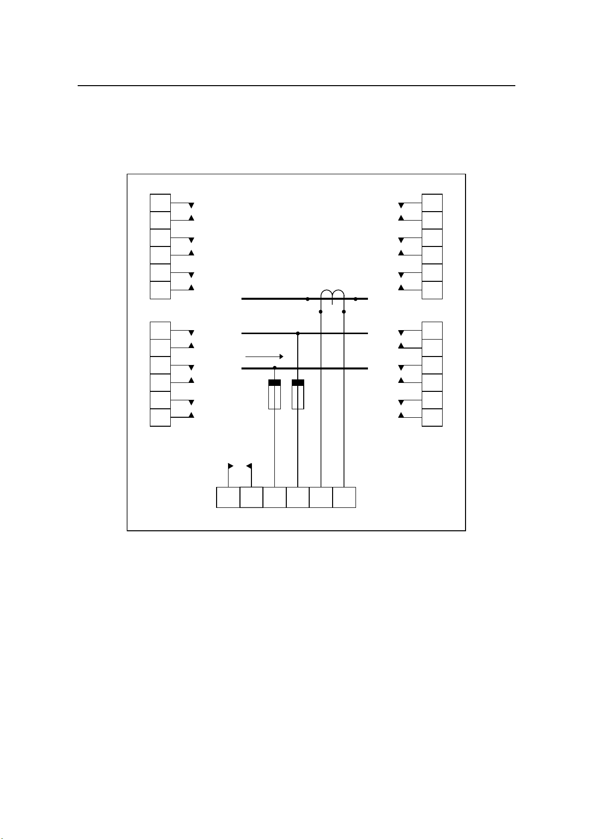
The NOVAR 300 should be connected to the system as shown in the appropriate diagrams
(Figures 1 and 2).
NOVAR 300 Operation & Maintenance Manual NOVAR_CM
Page 4 of 29
11
12
13
14
15
16
5
6
7
8
9
10
23
24
25
26
27
28
17
18
19
20
21
22
432129
7
8
9
10
11
12
A
B
C
30
1
2
3
4
5
6
P1
S1 S2
P2
To Load
Alarm
(if fitted)
For contact pairs fitted
see number of stages
FIGURE 1 - Wiring diagram for volt free contacts

NOVAR 300 Operation & Maintenance Manual NOVAR_CM
Page 5 of 29
432129
A
B
C
30
11
12
13
14
15
16
4
5
6
P1
S1 S2
P2
To Load
Alarm
(if fitted)
5
6
7
8
9
10
1
2
3
Common
28
27
26
25
24
23
12
11
10
22
21
20
19
18
17
9
8
7
For contact pairs fitted
see number of stages
FIGURE 2 - Wiring diagram for common contacts

NOVAR 300 Operation & Maintenance Manual NOVAR_CM
Page 6 of 29
1.2 DESCRIPTION AND OPERATION
Multi-stage controllers are available in standard units of 6 and 12 stages. These provide up
to 12 pairs of "volt-free" contacts.
The following switches are mounted on the controller front panel :
* An auto/manual control (upper button)
* A directional control marked +, 0, - (lower button)
* A ten-way programme selector switch
Depressing the auto/manual switch causes the Controller to enter MANUAL mode as
indicated by the LED adjacent to the switch. Capacitor stages can be switched 'in' by
pressing the directional control button once. Pressing this button once more places the
Controller in the MANUAL 'off' position and no further stages will be switched 'in' or 'out'.
Pressing this button once more will result in capacitor stages being removed until pressed
again. the three LED's associated with this button will, at all times, indicate the operational
mode.
When capacitors are being connected, a LED associated with the inductive (IND) control
lights. As they are being disconnected, a LED associated with the capacitive (CAP) control
lights.
The ten-way selector switch is used to select:
* The time interval between steps
* The sequence in which the stages are connected
* The limit which determines the number of steps taken in the sequence selected.
These are detailed in section 3.3.

NOVAR 300 Operation & Maintenance Manual NOVAR_CM
Page 7 of 29
2. TECHNICAL SPECIFICATION
2.1 RATINGS, OPERATING RANGES & FEATURES
Voltage Rating (Vn) 110 V, 120 V, 415 V, 480 V.
Others available in range 63.5 V to 500 V max.
Current Rating (In) 1 A or 5 A. Others available in the range 0.5 A to 5 A max.
Input Connections IA, VBC, or IB, VCA or IC, VAB
IR, VYB, or IY, VBR or IB, VRY,
IR, VST, or IS, VTR or IT, VRS.
Line Current Transformers Class 1, 5 VA
Operating Ranges
Voltage 85 ... 110 % Vn
Current 0...120 % In
Frequency 50/60 Hz
Humidity 0...93 % +2 % -3 % Relative (non-condensing)
Temperature Range Storage: -40... 80°C
Operating: -10... 55°C
Settings c/k 0.03...1.00
cos phi 0.80...1.00...0.95 leading
Overload Ratings 1.5 x Vn for 10 seconds
2 x In continuously
20 x In for 3 seconds
Isolation The controllers will withstand:
2 kV rms, 50/60 Hz for 1 minute between:
- all terminals to case
- current terminals to all others
- voltage terminals to all others
- output contact pairs (Volt Free versions)
Impulse Voltage Test The controller will withstand:
5 kV 1.2/50 us, 0.5J, to BS923 and IEC 255-22-1 between:
- all terminals and case
- current input terminals
- voltage input terminals
- output contacts (open)
- any pair of independent circuits
Output and Alarm contact
rating
Make 1250 VA, 500 V a.c. resistive
Carry 5 A a.c.
Break 5 A a.c.
Type: one normally open

NOVAR 300 Operation & Maintenance Manual NOVAR_CM
Page 8 of 29
2.1 RATINGS, OPERATING RANGES & FEATURES (cont.)
No-volt release All output contacts are disabled within 15 ms. After the
supply voltage is restored, normal operation is resumed,
and the outputs are energised in sequence after the
appropriate safety lockout time has elapsed.
Burdens Current circuit: 0.2 VA at In
Voltage circuit: 9 VA (6 stages energised)
15 VA (12 stages energised)
Net weight All models: 1.5 kg
Terminals Barrier type: M3.5
Plug-in wire size: 1...2.5 mm2(18...14 AWG)
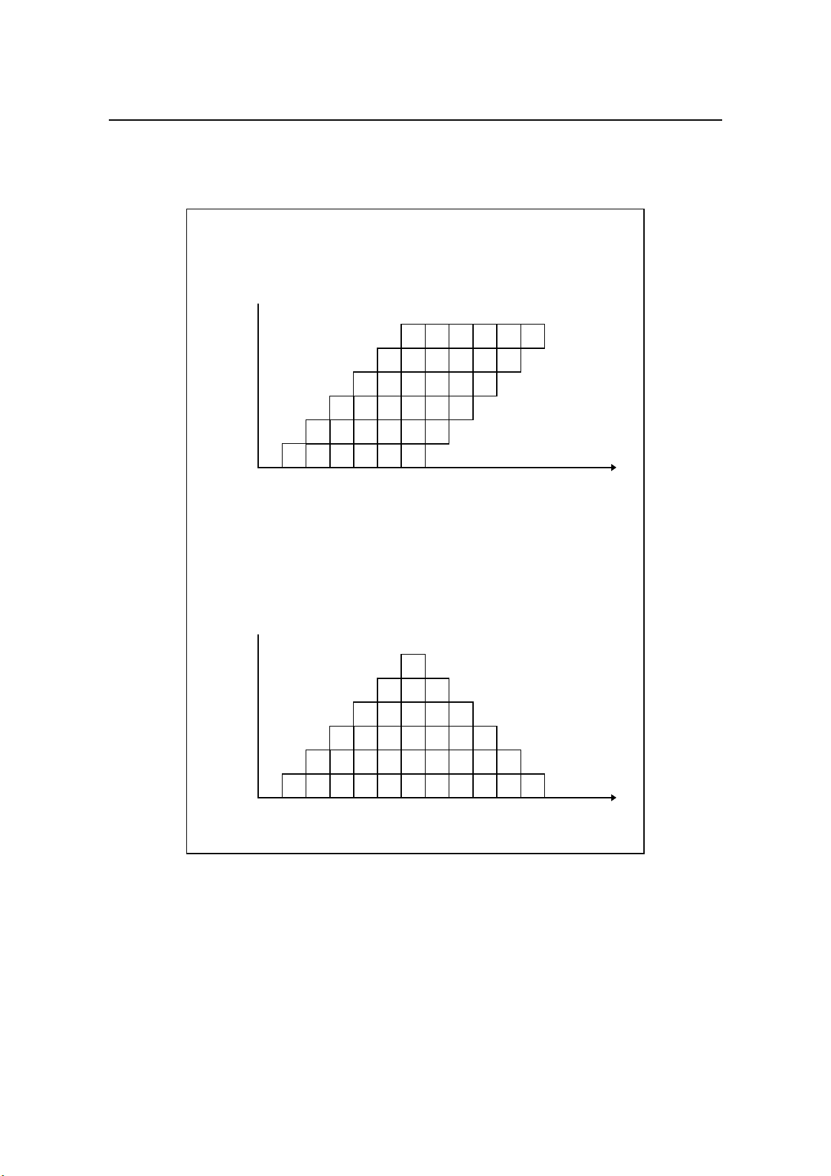
Switching style Rotational or linear (see Figure 3). Selected at time of
order. Rotational switching evens the contactor wear (for
the largest step size only) and generally reduces the
system response time. It is implemented for all sequences
on NOVAR 300, if requested.
Intelligent switching If twice the minimum capacitor size (or more) is required,
then the NOVAR will switch in a double step. This applies
for all sequences. For sequence 00 (1:1:1:1), the second
capacitor will be connected after an additional delay of two
seconds.
Limit selection Up to 12 plus alarm output. The maximum possible for any
configuration is determined by the number of relays fitted
and the selected sequence. If the selected value is too
high, the unit will automatically override it to the highest
allowable value.
Safety lockout The time required to safely discharge a capacitor can be
set to any of 8 different values. The NOVAR will not allow
any capacitor to be re-energised until this time has
elapsed.
Providing that the safety lockout time has passed, the
capacitor can be called after one fifth of the programmed
time. It is not possible to override this lockout time.

NOVAR 300 Operation & Maintenance Manual NOVAR_CM
Page 9 of 29
2.1 RATINGS, OPERATING RANGES & FEATURES (cont.)
Exit from manual The AUTO/MAN button allows the user to switch between
automatic and manual operating mode as required.
To safeguard against leaving a system indefinitely in
manual mode, an automatic exit has been included. This
will return the operating mode from manual to automatic
five minutes plus the selected safety lockout time after the
last manual mode operation. Relevant manual mode
operations are pressing the lower button and operation of
an output relay.
Models without the automatic exit from manual are
available.
Alarm output Signals failure to meet target cos ϕ
See also Self Test
Self Test At reset and every ten minutes in operation, the NOVAR
executes an internal hardware check for correct
functioning. During this process, the model number will be
displayed.
If the unit fails this self test, the IND and CAP LEDs are
toggled and the alarm relay (if fitted) is also “flashed “ in
time with this.
NOVAR 300 Operation & Maintenance Manual NOVAR_CM
Page 10 of 29
1 1 1 1 1 1
2 2 2 2 2 2
3 3 3 3 3 3
4 4 4 4 4 4
5 5 5 5 5 5
6 6 6 6 6 6
1
2
3
4
5
6
Capacitors
connected
Switching steps Time
ROTATIONAL SYSTEM RESPONSE
1 1 1 1 1 1
2 2 2 2 2 2
3 3 3 3 3 3
4 4 4 4 4
5 5 5
6
1
2
3
4
5
6
Capacitors
connected
Switching steps Time
LINEAR SYSTEM RESPONSE
1
2
1
3
2
1
2
1 1
FIGURE 3 - Rotational/linear capacitor switching

NOVAR 300 Operation & Maintenance Manual NOVAR_CM
Page 11 of 29
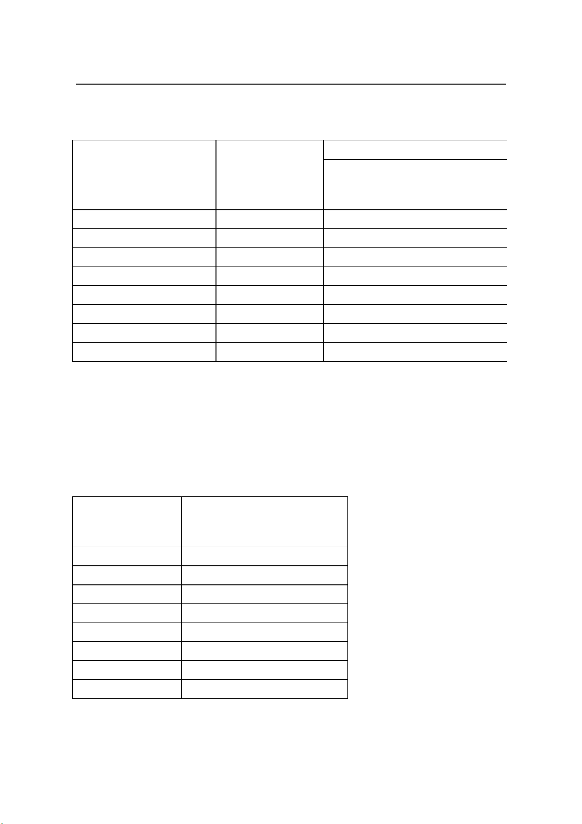
2.2 ELECTROMAGNETIC COMPATIBILITY (EMC)
Phenomenon Standard Limits Met and Claimed
Conducted EN50081-1 EN55022:1987CClass B (Table II)
Emissions 1992
Radiated EN50081-1 EN55022:1987R Class B (Table IV)
Emissions 1992
Electrostatic prEN50082-2 8 kV air discharge, prEN50082-2: 9.1.2
Discharge 1991 4 kV contact discharge,
(IEC 801-2) Informative Annex: 1.1.4
Fast prEN50082-2 2 kV Input AC power ports (direct)-prEN50082-2:9.5.1
Transients 1991 4 kV Output ports (cap. clamp)- prEN50082-2: 9.5.1
(IEC 801-4)
Radiated prEN50082-2 10 V/m (*modulated 80% A.M., 1 kHz)
Immunity 1991 26 MHz to 1000 MHz.
(IEC 801-3) prEN50082-2: 9.1.1 and * Informative Annex 1.1.2
Conducted prEN50082-2 10 V rms (modulated 80% A.M., 1kHz)
Immunity 1991 150 kHz to 29 MHz
(IEC 801-6)
Burst Test IEC255-22-1 1 MHz burst disturbance test Class III
1988 2.5 kV common mode, 1 kV differential mode
C- Conducted Emissions Limits: 0.15 MHz to 0.5 MHz ,66-56 dBµV Q-P,56-46 dBµV Ave.,
(to EN55022:1987 Class B) limits decrease linearly with log frequency.
0.5 MHz to 5 MHz, 56 dBµV Q-P, 46 dBµV Ave.
5 MHz to 30 MHz, 60 dBµV Q-P, 50 dBµV Ave.
R- Radiated Emissions Limits: 30 MHz to 230 MHz, 30 dBµV/m (at 10m).
(to EN55022:1987 Class B) 230 MHz to 1000 MHz, 37 dBµV/m (at 10m).
2.3 EUROPEAN LOW VOLTAGE DIRECTIVE (LVD)
Designed to IEC1010-1 requirements.
WARNING
The circuit boards are susceptible to electrostatic discharge (ESD) and appropriate ESD
protection should be taken to avoid damage, when handling or adjusting these. The
8 kV ESD susceptibility rating applies with the front label fitted.
NOVAR 300 Operation & Maintenance Manual NOVAR_CM
Page 12 of 29
3. COMMISSIONING
WARNINGS
1 Installation, commissioning and maintenance should only be carried out by suitably
qualified personnel.
2 Terminations exposed during installation, commissioning and maintenance may
present a hazard unless the equipment is electrically isolated.
3 The equipment should only be operated as intended e.g. with the covers in place,
and within the specified electrical and environmental limits.
4 No capacitor controller is suitable for the isolation of system voltage from capacitor
banks for the purpose of maintenance etc. Some NOVAR units are specially
programmed to not return to 'auto' mode from 'manual'. These units will still reset to
'auto' on loss of volts and so are still unsuitable for capacitor bank isolation.
Before connection of the NOVAR into a customer's system, ensure that the safety lockout
time programmed into the NOVAR is equal to or greater than that required for safe
discharge of system capacitors. Unless this has been specified on ordering, the NOVAR will
be set to 60 seconds. If the system requires a greater time this must be set before powering
up the NOVAR.
3.1 SYSTEM CONNECTIONS
Refer to Figures 1 and 2.
The NOVAR power factor controllers employ solid state circuitry for the measurement of
vars. The vars determination is directionally sensitive. Voltage and current supplies to the
controllers must be mutually at 90 degrees when the system is at unity power factor.
On a three phase supply, the required phase shift is obtained by connecting the controller
current input to a current transformer in one phase, and connecting the voltage input across
the remaining two phases. Any phase can be used for the current input if the correct phase
relationship exists between current and voltage.
The following combinations are possible :
CT in Phase Voltage Connections
(across phases)
A(R) (R) BC (ST) (YB)
B(S) (Y) CA (TR) (BR)
C(T) (B) AB (RS) (RY)
Connections between the controller and the capacitor contactors are also shown in Figures
1 and 2.

NOVAR 300 Operation & Maintenance Manual NOVAR_CM
Page 13 of 29
3.2 USER ADJUSTMENTS
The following user adjustments are available and should be set during commissioning.
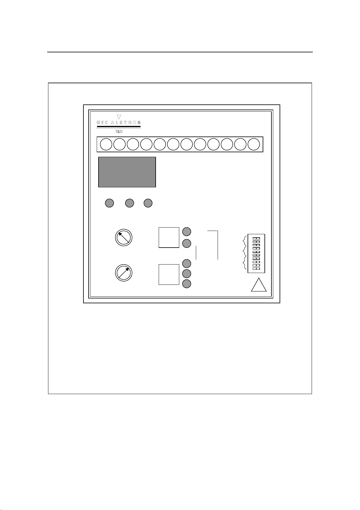
Refer to also to Figure 4.
Parameter Fascia Key Means of Selection
Sequence GDIL switch *
Time GDIL switch *
Limit GDIL switch *
C/k CPotentiometer
cos ϕDPotentiometer
Warning
Due to the presence of electrostatic sensitive devices on the printed circuit board, care must
be taken to effectively earth oneself before commencing commissioning. The
recommended method is to use a standard wrist strap that is connected to earth.
NOVAR 300 Operation & Maintenance Manual NOVAR_CM
Page 14 of 29
1
Model 305
Novar
300
% Vn
% In
COS ϕ
POWER CAP IND
A
UTO
MANUAL
+
0
-!
COS ϕ
C/K
2345678910 11 12
% Vn
% In
COS ϕ
01
Sequence
Time
Limit
E
F
D
C
G
HJK
B
A
Fascia Key
A - Secret-until-lit display of energised stages
B - High definition liquid crystal display
C - C/K setting
D - COS ϕsetting
E - Dual mode button: auto/manual
F - Dual mode button: capacitor switching (man) and display selection (auto)
G - DIL switch (sequence, time and limit setting)
H - Power on indication LED
J - Switching in progress, circuit is capacitive
K - Switching in progress, circuit is inductive
1
2
3
4
5
6
7
8
9
10
FIGURE 4 - NOVAR indication and user adjustments

NOVAR 300 Operation & Maintenance Manual NOVAR_CM
Page 15 of 29
3.3 SETTING OF DUAL-IN-LINE SWITCH
Settings of sequence, lockout time and stage limit should be set prior to powering up the
NOVAR. When a controller leaves the factory, the DIL switch will be pre-set to the following
default values, regardless of model type, unless specified on the order. Refer to Figure 5.
SEQUENCE = 1:1:1:1:1 . . .
TIME = 60 seconds
LIMIT = the number of stages of the controller, i.e., for 6 stages limit equals 6.
If these settings are suitable for the user’s application, this section may be ignored.
1
2
3
4
5
6
7
8
9
10
01
LIMIT
TIME
SEQUENCE
FIGURE 5 - DIL switch factory default settings
3.3.1 Sequence
The settings of this switch determine the controller's sequence, safety lockout time and limit
of switching.
Note: The settings can only be altered on-site on the NOVAR 305 models.
Unless otherwise requested, the NOVAR will have a sequence setting of 1:1:1:1 (sequence
0), a safety lockout time of 60 seconds and a limit equal to the number of stages supplied
with the unit.
Eight sequence settings are available. The sequence controls the number of steps taken for
a desired number of capacitor stages. For instance, sequence 00 is used for capacitors
which are all the same size. Alternatively, sequence 07 is used where each of the first four
steps is progressively twice the size of the previous step (a ratio of 1:2:4:8).
The correct switch setting should be selected using table 1 as a guide. In the expanded
display mode the setting can be checked by pressing the lower push-button once more (a
digit 5, representing the letter S will appear in digit position 4 of the display).
NOVAR 300 Operation & Maintenance Manual NOVAR_CM
Page 16 of 29
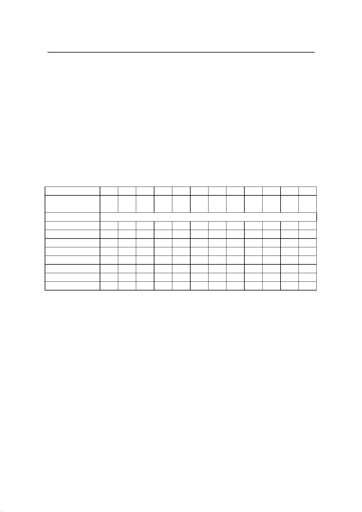
Table 1 - Sequence settings
Max no. of steps per controller
Switches Number of Stages
Sequence
Number
Sequence 1 2 3 1 3 6 9 12
00 1:1:1:1:1 etc 0 0 0 1 3 6 9 12
01 1:1:2:2:2 etc 1 0 0 1 4 10 16 22
02 1:2:2:2:2 etc 0 1 0 1 5 11 17 23
03 1:2:3:3:3 etc 1 1 0 1 6 15 24 33
04 1:2:3:4:4 etc 0 0 1 1 6 18 30 30
05 1:2:4:4:4 etc 1 0 1 1 7 19 31 31
06 1:2:3:6:6 etc 0 1 1 1 6 24 30 30
07 1:2:4:8:8 etc 1 1 1 1 7 31 31 31
3.3.2 Safety Lockout Time
Proper selection of switching time delay is a function of the electrical system and capacitor
voltage rating. Usually, as a guide, the time interval must be larger than the discharge time
of the capacitor being switched. This time required for discharge is known as the safety
lockout time. The dual-in-line switch should be set to the desired time by reference to Table
2. In expanded display mode, the setting selected can be checked by pressing the lower
push button once more (a ‘t’ symbol will appear in digit 4 of the display).
Table 2 - Lockout time settings
Safety Lockout
Time (Seconds)
Switches
456
10 000
20 100
30 010
60 110
180 001
300 101
480 011
600 111
NOVAR 300 Operation & Maintenance Manual NOVAR_CM
Page 17 of 29
3.3.3 Stage Limit
The number of stages switched can be limited to anywhere between 1 and 12. A limit
function prevents unused stages being switched where no capacitors are present. Table 3
shows, for each sequence selected, the switch positions necessary to achieve the desired
stage limit. This selected stage limit will equate to a finite number of steps depending on the
sequence chosen. In expanded display mode, the limit selected can be checked by
pressing the lower push button once more (an ‘L’ will appear in the fourth display digit).
Note: The limit is the number of capacitors connected to the NOVAR and must be set
correctly. If the limit is set higher than the number of capacitors connected then the system
response will be slowed down.
Table 3 - Limit settings
Stage Limit 12345678910 11 12
Switch number 7 8 9 10 7 8 9 10 7 8 9 10 7 8 9 10 7 8 9 10 7 8 9 10 7 8 9 10 7 8 9 10 7 8 9 10 7 8 9 10 7 8 9 10 7 8 9 10
Switch setting 1 0 0 0 0 1 0 0 1 1 0 0 0 0 1 0 1 0 1 0 0 1 1 0 1 1 1 0 0 0 0 1 1 0 0 1 0 1 0 1 1 1 0 1 0 0 1 1
Sequence number Maximum number of steps
00 12345678910 11 12
01 1246810 12 14 16 18 20 22
02 1357911 13 15 17 19 21 23
03 136912 15 18 21 24 27 30 33
04 13610 14 18 22 26 30 ---
05 13711 15 19 23 27 31 ---
06 13612 18 24 30 -----
07 13715 23 31 ------

NOVAR 300 Operation & Maintenance Manual NOVAR_CM
Page 18 of 29
3.4 SETTING OF C/K VALUE
The c/k potentiometer should be set according to the following equation;
C/k
Smallest Capacitor
Step Size in vars
3VI 5=××
×
where: V = nominal primary system voltage
I = primary rating of the current transformer
This is indicated on the display by the small c symbol in the upper part of digit 4 if the
expanded display mode is selected on models having displays.
3.4.1 Examples of Calculation and C/K Settings
Example 1
A 25 kvar capacitor operating on a 415 V, 3 phase supply, is controlled by a single stage
controller operating via a 200/5 CT but without a VT.
C = 25,000 vars, V = 415 V, I = 200 A
C/k 25,000 5
3 415 200 0.87=×
×× =
The NOVAR 300 is scaled to give a deadband of 150 % nominal capacitor size.
(i.e. NOVAR 300 will switch capacitors in circuit when the input lagging vars exceed three
quarters of a capacitor step size . NOVAR 300 will switch capacitors out of circuit when the
input leading vars exceed three quarters of a capacitor step size .)
The value of C/K can be directly entered into the unit.
Example 2
A multi-stage unit controls a 6 stage capacitor bank. Each stage is rated at 100 kvar. The
voltage is 415 V and the CT is 1000/5. There is no VT.
C = 100,000 vars, V = 415 V, I = 1,000 A
C/k 100,000 5
3 415 1,000 0.70=×
×× =
As above, this value can be directly entered into the unit.

NOVAR 300 Operation & Maintenance Manual NOVAR_CM
Page 19 of 29
Example 3
A multi-stage unit controls a six stage capacitor bank. Each stage is rated at 100 kvar. The
VT is 3.3 kV/110 V and the CT ratio is 500/5.
C = 100,000 vars, V = 3 300 V, I = 500 A
C/k 100,000 5
3 3,300 500 0.17=×
××
=
As above, this value can be directly entered into the unit.
NB: The NOVAR 300 calculation has been formulated in such a way that it will work for any
value of secondary amps and volts which can be used with the unit. However, if the nominal
secondary amps used is other than 5 amps, the value represented by the scalings on the
c/k potentiometer will no longer be the actual capacitor starting current in amps. This makes
no difference to the operation of the unit.The NOVAR 300 ratings must match the
secondary rating of any CT and VT used.
3.5 SETTING OF TARGET COS PHI
This is set using the potentiometer, labelled “cos ϕ“, located on the front panel.
To make use of the expanded display mode, the lower push-button should be pressed once
more .The display will now indicate the potentiometer setting and a large C in the fourth digit
of the display.
kW C/k
Minimum
(Deadband)
0.03
Lead
Lag
kvar
C/k
Maximum
(Deadband)
1.0
Range of C/k adjustment for cos ϕ= 1.0
kW
kvar
Range of cos ϕfor a given C/k
C/k
C/k
ϕ1
ϕ2
Lead
Lag
cos ϕ
adjustment
0.80 lag to
0.95 lead
FIGURE 6 - Ranges for C/k and cos ϕsettings

NOVAR 300 Operation & Maintenance Manual NOVAR_CM
Page 20 of 29
3.6 CONNECTION ERRORS
NOVAR 300 gives a certain amount of information to assist with connection. There are six
possible ways in which it is possible to connect a system. Of these six, only one is correct.
For three of the others, NOVAR 300 will give indication of a connection error as follows.
At system unity power factor, the NOVAR 300 error mode is looking for a phase angle of
90°between amps and volts. As a system can in theory be operating anywhere within a
band of 90°either side of this, the error mode looks for its inputs to be within this band.
Refer to Figure 4 for vector diagrams showing the correct and incorrect connections.
The correct connection (a)
Input is IAwith VBC.
For this case, the NOVAR will go straight into AUTO mode.
The most common connection error is that of a reversed CT (b). In this case the NOVAR
will display 270°for a system at unity power factor.
If VBA is selected instead of VBC (c) then the NOVAR will display 150°.
If VCA is selected instead of VBC (d) then the NOVAR will display 210°.
The above values will change if the system is not at unity power factor (e.g. if the system is
at 40°lagging then a CT reversal would appear as 230°).
Because VAB or VAC are within the above stated bands, then the NOVAR is not able to
distinguish between these and a system working at the relevant power factor.
If VAB is selected (e) then the NOVAR will display a cos ϕof 0.5 leading corresponding to an
angle of 60°leading.
If VAC is selected (f) then the NOVAR will display a cos ϕof 0.5 lagging corresponding to an
angle of 60°lagging.
3.7 USE OF EXPANDED DISPLAY
Once it is known that the NOVAR is connected into the system correctly, it is necessary to
set up the working parameters of the unit.
If a display model is being used, then it enables more accurate settings if expanded display
mode is now entered. This is achieved by pressing the lower push button for more than 5
seconds.
Table of contents
Other Novar Controllers manuals


Popular Controllers manuals by other brands

Emerson
Emerson Fisher 630 Series installation guide

Matelec
Matelec Hydrowhiz FPC-63X21 quick start guide

Siemens
Siemens RVP550 installation instructions

LAE electronic
LAE electronic CDC122T1R2 Instructions for installation and use

Honeywell
Honeywell AQS51-KAM Product data

Johnson Controls
Johnson Controls tyco PowerSeries Neo Reference manual

Siemens
Siemens SKP Series Technical instructions

Garnet
Garnet SEELEVEL PosiGround 672-H manual

ASCON TECNOLOGIC S.r.l.
ASCON TECNOLOGIC S.r.l. TLK48 B quick guide

CBS ArcSafe
CBS ArcSafe RSA-104 Installation and operation

Rockwell Automation
Rockwell Automation Allen-Bradley Logix 5000 Series Programming manual

Honeywell
Honeywell Touchpoint Plus Safety manual


