Tonghui TH1952 User manual

OPERATION MANUAL
TH1952
51/2 Digit Multimeter
Changzhou Tonghui Electronic Co., Ltd.
www.tonghui.com.cn

2
Manual Printing History
The manual printing data and part number indicate its current edition. The printing date changes when a
new edition is printed. The manual part number changes when extensive technical changes are
incorporated.
October 2015……………………………………………………………………………………………………………First Edition
Announcement
The description of the manual may not cover all contents of the instrument, and our company
is subject to change and to improve the performance, function, inner structure, appearance,
accessory and package of the instrument without notice. If there is puzzle caused by
inconsistency of manual and instrument, then you can contact with our company by the
address on the cover.

3
Contents
Chapter 1 General Information .................................................................................................................5
1.1 Feature Overview ........................................................................................................................5
1.2 Operating Environment ...............................................................................................................5
1.3 Dimensions and Weight ..............................................................................................................6
1.4 Safety symbols and Precautions .................................................................................................6
1.5 Incoming Inspection ....................................................................................................................6
1.6 Warranty......................................................................................................................................7
1.7 Limitation of Warranty..................................................................................................................7
Chapter 2 TH1952 Overview ....................................................................................................................8
2.1 Brief introduction .........................................................................................................................8
2.2 Front Panel Summary .................................................................................................................8
2.2.1 Annunciators on Screen ..................................................................................................10
2.2.2 Front Panel Menu Reference ..........................................................................................11
2.2.3 Front Panel Menu Overview............................................................................................12
2.3 Rear Panel Summary ................................................................................................................13
2.4 Power up ...................................................................................................................................14
2.4.1 Power Line Connection ...................................................................................................14
2.4.2 Input Terminals................................................................................................................14
2.4.3 High Energy Circuit Safety Precautions ..........................................................................15
2.4.4 Power-on Defaults...........................................................................................................15
Chapter 3 Basic Measurements .............................................................................................................17
3.1 Preparation................................................................................................................................17
3.2 Measuring Voltage.....................................................................................................................17
3.3 Measuring Current.....................................................................................................................18
3.4 Measuring Resistance...............................................................................................................20
3.5 Measuring Continuity.................................................................................................................21
3.6 Measuring Diode .......................................................................................................................21
3.7 Measuring temperature .............................................................................................................21
3.8 Measuring Frequency................................................................................................................22
3.9 Measuring capacitance .............................................................................................................22
3.10 Math Functions........................................................................................................................22
3.10.1 dB Calculation ...............................................................................................................22
3.10.2 dBm Calculation ............................................................................................................23
3.10.3 Percent..........................................................................................................................24
3.10.4 mX+b.............................................................................................................................25
3.10.5 Max/Min data statistics ..................................................................................................25
Chapter 4 Measurement Options ...........................................................................................................27
4.1 Measurement configuration.......................................................................................................27
4.1.1 Range .............................................................................................................................27
4.1.2 Relative operation ...........................................................................................................28
4.1.3 Digits and Rate................................................................................................................28
4.2 Trigger Operations.....................................................................................................................29

4
4.2.1 Trigger procedure............................................................................................................29
4.2.2 Measurement Sample .....................................................................................................30
4.2.3 Reading Hold ..................................................................................................................30
4.2.4 External trigger................................................................................................................31
4.3 Limit Operations ........................................................................................................................31
4.4 System Operations....................................................................................................................32
4.4.1 Beeper Control ................................................................................................................32
4.4.2 Key Sound.......................................................................................................................32
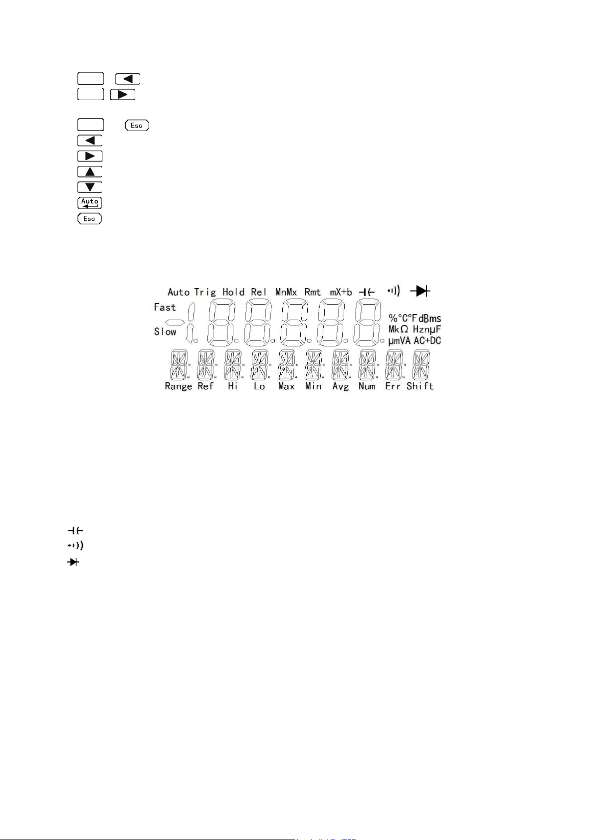
4.4.3 Display ............................................................................................................................32
4.4.4 Calibration .......................................................................................................................33
Chapter 5 Remote Operation .................................................................................................................34
5.1 RS-232 remote interface ...........................................................................................................34
5.1.1 RS-232 Interface Instruction............................................................................................34
5.1.2 RS-232 Interface Operation ............................................................................................35
5.2 USB Interface............................................................................................................................37
5.2.1 USB introduction .............................................................................................................37
5.2.2 USB Communication.......................................................................................................37
5.3 Handler Interface.......................................................................................................................37
Chapter 6 SCPI Command Reference ...................................................................................................40
6.1 Command structure...................................................................................................................40
6.2 Command Syntax......................................................................................................................40
6.2.1 Commands and command parameters ...........................................................................40
6.2.2 Short-form Rules .............................................................................................................42
6.2.3 Basic Rules of Command Structure ................................................................................42
6.2.4 Multiple Command Rules ................................................................................................43
6.2.5 Command Path Rules .....................................................................................................43
6.3 Command Reference ................................................................................................................43
6.3.1 DISPlay subsystem .........................................................................................................43
6.3.2 FUNCtion subsystem ......................................................................................................45
6.3.3 FUNCtion2 subsystem ....................................................................................................46
6.3.4 UNIT subsystem..............................................................................................................46
6.3.5 CALCulate subsystem.....................................................................................................47
6.3.6 VOLTage subsystem .......................................................................................................52
6.3.7 CURRent subsystem.......................................................................................................57
6.3.8 RESIister subsystem.......................................................................................................61
6.3.9 FREQuency and PERiod subsystem ..............................................................................64
6.3.10 CAPacitance subsystem ...............................................................................................66
6.3.11 HOLD subsystem ..........................................................................................................69
6.3.12 TRIGger subsystem ......................................................................................................70
6.3.13 FETCH Subsystem .......................................................................................................71
6.3.14 SPEED Subsystem .......................................................................................................71
6.3.15 RETURN Subsystem ....................................................................................................72
6.3.16 Common Commands ....................................................................................................73

5
Chapter 1 General Information
Thanks very much for choosing and using our product. If you have any questions after reviewing this
manual, please contact your local representative or call directly to our application engineers for further
consultation.
1.1 Feature Overview
TH1952 is a 5½ digital multimeter with high accuracy, stability and speed. The digital multimeter provides
a maximum measurement speed of 200 readings/sec. TH1952 has a 0.012% DC voltage basic accuracy,
0.05% basic resistance accuracy and other high performance.
TH1952 has broad measurement ranges:
5½ reading with dual-display
DC voltage from 1μV to 1000V
AC voltage from 1μV to 750V
AC/DC voltage from 1μV to 750V (RMS)
DC current from 10nA to 12A
AC current from 10nA to 12A
AC/DC current from 10nA to 12A (RMS)
Resistance measurement from 1mΩto 100MΩ
Frequency from 1Hz to 1MHz
Some additional capabilities of Model TH1952:
Full range of functions: In addition to those listed above, TH1952 functions include period, dB,
dBm, continuity, diode testing, max, min and percent.
Programming languages and remote control interfaces: TH1952 provides the SCPI
programming language and the remote control interface port RS-232C, USB interface and
Handler interface.
Closed-cover calibration: The multimeter can be calibrated either from the front panel or
through the remote control interface. Manual Calibration function is added for your
convenience.
1.2 Operating Environment
Power supply: 110V/220V ±10%
Line frequency: 50Hz / 60Hz ±5%
Power consumption: ≤10VA
Operating temperature: 0℃to 45℃
Humidity: ≤90%RH

6
1.3 Dimensions and Weight
Dimensions(W×H×D):277mm×115mm×354mm
Net weight: Around 2.5Kg
1.4 Safety symbols and Precautions
The symbol on the instrument indicates that user should refer to the operating instructions located
in the manual before performing.
The symbol on the instrument shows that high voltage may be present on the terminal(s). Be
careful to avoid personal contact with these voltages.
The symbol on the instruments means earth grounding.
The WARNING heading used in the manual explains high voltage danger that might result in personal
injury or death. Always read the associated information very carefully before performing the indicated
procedure.
The CAUTION heading in the manual reminds user that hazards could damage the instruments if not
according to operating instructions. Such damage may invalidate the warranty.
1.5 Incoming Inspection
The TH1952 was carefully inspected mechanically and electrically before shipment. After unpacking all
items from the shipping carton, please check for any obvious signs of physical damage that may have
occurred during transportation. Report any damage to the shipping agent immediately. Save the original
packing carton for possible future reshipment. The following items are included with every Model
TH1952 order:
Model TH1952 51/2Digital Multimeter
Test leads (Model TH26036)
Power cord
Two 0.5A fuses
Two 1A fuses
Operation Manual
Quality and warranty certificate
Test report
Other optional accessories if ordered
Verify that you have received all the items above when you get multimeter. If anything is missing, please
contact our representative or our sales office.

7
1.6 Warranty
Tonghui warrants this product to be free from defects in material and workmanship for a period of 2 years
from the date of shipment. During the warranty period, we will, at our option, either repair or replace any
product that proves to be defective.
1.7 Limitation of Warranty
This warranty does not apply to defects resulting from product modification without our express written
consent, or misuse of any product or part. This warranty also does not apply to fuses, software, or
problems arising from normal wear or failure to follow instructions.
THIS WARRANTY IS IN LIEU OF ALL OTHER WARRANTIES, EXPRESSED OR IMPLIED, INCLUDING ANY
IMPLIED WARRANTY OF MERCHANTABILITY OR FITNESS FOR A PARTICULAR USE. THE REMEDIES
PROVIDED HEREIN ARE BUYER’S SOLE AND EXCLUSIVE REMEDIES.
NEITHER TONGHUI ELECTRONICS NOR ANY OF ITS EMPLOYEES SHALL BE LIABLE FOR ANY DIRECT,
INDIRECT, SPECIAL, INCIDENTAL OR CONSEQUENTIAL DAMAGES ARISING OUT OF THE USE OF ITS
INSTRUMENTS AND SOFTWARE EVEN IF TONGHUI ELECTRONICS HAS BEEN ADVISED IN ADVANCE
OF THE POSSIBILITY OF SUCH DAMAGES. SUCH EXCLUDED DAMAGES SHALL INCLUDE, BUT ARE
NOT LIMITED TO: COSTS OF REMOVAL AND INSTALLATION, LOSSES SUSTAINED AS THE RESULT OF
INJURY TO ANY PERSON, OR DAMAGE TO PROPERTY.

8
Chapter 2 TH1952 Overview
2.1 Brief introduction
TH1952 51/2 Digital Multimeter is a multi-functional voltage/current/resistance meter with fast speed and
high accuracy. TH1952 provides high brightness VFD dual-display, which brings you great convenience
for display of multiple function combinations. The inherent test platform and system performance make
TH1952 an all-purpose measurement solution.
Convenient test platform features:
High brightness VFD dual-display
Built-in arithmetical operation function
Short and diode test function
Manual setup of reading hold function
Portable shape design
Flexible system performance:
RS-232 interface
Handler interface
USB interface
Standard programming language SCPI
Max. ADC sampling rate can be 200/sec
Limit test with HI/LO signal can help you select good products
2.2 Front Panel Summary
The front panel of the TH1952 is shown in Figure 2-1. This figure includes some important abbreviated
information that should be reviewed before operating the instrument.

9
Figure 2-1 TH1952 Front Panel
1. Function keys
Select measurement function: DC voltage (DCV)/ DC current (DCI), AC voltage (ACV) /AC current
(ACI), resistance (Ω)/continuity ( )/diode( ), temperature (Temp)/ frequency (Freq), capacitance/
dB, AC+DC/dBm.
2. Math function keys
Select the math function: Rel/mX+b, Max/Min/%.
3. Trig/Hold Key
Tr ig
Trigger a measurement from the front panel.
Shift
→
Tr ig
Hold a stable reading on the display when selected numbers of samples are
within the selected tolerance.
4. Shift/Local keys
Shift
Used to access shifted keys.
Shift
(LOCAL) Cancel RS232C remote control mode and back to the LOCAL mode.
5. 2nd Display key
Control the secondary parameter display.
→ Turn on the Limit function.
6. Use this key to select and save settings in SETUP page; to switch between auto
and manual ranging in MEAS page.
7. Range keys
Select a higher range.
Select a lower range.
8. Speed key
Select slow speed.
Select fast speed.
Function ke
y
s
Primary display
Secondary
display
Switch S
p
eed Ran
g
e
Math function ke
y
s
T
est terminal Current
Input fuse
Ente
r
Direction
key
Menu operation
2nd dis
p
la
y
ke
y
Tri
g
/Hold ke
y
Shift/local ke
y

10
Shift
+ Select 4 1/2 display.
Shift
+Select 5 1/2 display.
9. Menu operation keys
Shift
→Open/Close menu
Move through selections within menu level, command level or parameter level
Move through selections within menu level, command level or parameter level.
Move up a level.
Move down a level.
(Enter) Save the change made on “parameter” level.
Quit the menu.
2.2.1 Annunciators on Screen
Figure 2-2 Display Annunciators
AUTO Auto ranging state indication
TRIG Indicates external trigger (front panel, bus) selected.
HOLD Reading HOLD function is enabled.
REL Relative reading displayed.
MnMx Datastatisticsfunction is enabled.
Rmt Remote operation is in progress.
mX+b Coefficient adjustment mX+b function is enabled.
Capacitance measurement function is enabled.
Continuity measurement function is enabled.
Diode measurement function is enabled.
Range Secondary parameter display
Ref Zero ref under dB/dBm
Hi Limit indicates the upper limit testing results
Lo Limit indicates the lower limit testing results
Max Maximum value of data statistics
Min Minimum value of data statistics
Avg Average value of data statistics
Num Number of data statistics
ERR Hardware or remote control error detected
SHIFT Accessing shifted keys

11
2.2.2 Front Panel Menu Reference
A:MATH MENU
1:HILIMIT Set the high limit for limit testing
2: LO LIMIT Set the low limit for limit testing
3: PERC REF Set the reference value for PERCENT function
4:dBREF Set the dB reference voltage value
5: dBm REF Set the dBm reference impedance value.
6: MxB MSET Set the M parameter for Mxb
7:MxB BSET Set the b parameter for Mxb
8:CONTFLAG Set the link reference for continuity function
B:TRIGger MENU
1: TRIG MOD Set the trigger mode
2: HOLD WIN Set the reading hold sensitivity band
3: HOLD CNT COUNT of readings for reading hold
4:RDGS STOR Data storage function is enabled
5:RDGS COUN Set the data storage number
6:SCAN RDGS Scan the saved data
C:SYStem MENU
1: BAUD RATE
2: BEEP START
3: KEY SONG
4: REVISION
5: ZERO CAL
6: TEMP TNST
7: PLACE 4/5
8:HANDLER:IO
9:SCALALLOW
Set the baud rate
Enable or disable the beep function
Enable or disable the key sound
Version number
Zero clearing calibration
Switch between degree centigrade ℃and Fahrenheit degree ℉
Function selection between 4 1/2 and 5 1/2
Set the HANDLER interface and select the internal or external power
Enable or disable the manual calibration function

12
2.2.3 Front Panel Menu Overview
The menu is organized in a top-down tree structure with three levels (menus, commands and
parameters) as shown in Figure 2-3. You can use down ( ) or up ( ) to move menu tree from
one level to another. Each of the three levels has several horizontal choices which you can view by using
left ( ) or right ( ). Press to confirm.
Figure 2-3 Menu Tree
Menus
Commands
Parameters

13
2.3 Rear Panel Summary
The rear panel of TH1952 is shown in Figure 2-4. This section includes important information that should
be reviewed before operating the instrument.
Figure 2-4 TH1952 Rear Panel
1. HANDLER interface
Use a standard DB-9 hole-type connector. Use external signal to trigger test
2. RS-232C Connector
Use a standard DB-9 needle-type connector for RS-232 operation.
3. USB interface
Use a USB-B square connector. Use USB wire to make remote operation.
4. Grounding
Chassis Grounding terminal
5. Label
Serial number for this instrument
6. Power-Line Fuse-Holder Assembly
TH1952 can be configured for line voltage of 110/220V±10% AC at line frequency of 50/60Hz±5%.
Power-line fuse is used for instrument protection. (220V/500mA or 110V/1A)
Note: Please use the same-type fuse or contact your nearest Tonghui sales and service office.
To verify and replace the fuse, remove the power cable and pull out the fuse holder.

14
2.4 Power up
2.4.1 Power Line Connection
Follow the procedure below to connect the TH1952 to line power and turn on the instrument.
1. Check to make sure that the line voltage is in the range of 110V/220V±10% and line frequency is in
the range of 50Hz/ 60Hz±5%) before connecting the power cord.
CAUTION: Operating the instrument on an incorrect voltage may cause damage to the
instrument, possibly voiding the warranty.
2. Before plugging in the power cord, make sure that the front panel power switch is in the off position.
3. Connect the female end of the supplied power cord to the AC receptacle on the rear panel. Connect
the other end of the power cord to a grounded AC outlet.
WARNING: The power cord supplied with the Model TH1952 contains a separate ground wire for
use with grounded outlets. When proper connections are made, instrument chassis
is connected to power line ground through the ground wire in the power cord. Failure
to use a grounded outlet may result in personal injury or death due to electric shock.
4. Turn on the instrument by pressing the front panel power switch and get ready for measuring.
2.4.2 Input Terminals
1A-12A large current input high-terminal
Input-High terminal for voltage, resistance, capacitance,
diode, continuity and frequency measurements
Common terminals
1mA~100mA range DC/AC current input terminal for
DC/AC current measurements
0.5A ~ 250V range fuse

15
Function Input Terminals Maximum Allowable Input
DCV to COM 1010V DCV
ACV, FREQ to COM 760V ACV
100mA current 500mA to COM 120mA DC or 120mA AC
10A current 12A to COM 12A DC or 12A AC
Resistance, diode,
continuity
to COM 200V DC or 200V AC RMS
All functions Any terminals to earth 1000V DC 1000V AC Peak
Capacitance to COM 1.2mF
Temperature to COM -200—650℃
2.4.3 High Energy Circuit Safety Precautions
To optimize safety when measuring voltage in high energy distribution circuits, read and use the
directions in the following warning.
When making measurements in high energy circuits, use test leads and accessories that meet the
following requirements:
Test leads and accessories must be fully insulated.
Only use test leads that can be connected to the circuit (e.g., alligator clips, spade lugs, etc.) for
hands-off measurements.
Do not use test leads or accessories that decrease voltage spacing. This diminishes arc
protection and creates a hazardous condition.
Use the following sequence when measuring high energy circuits:
1. De-energize the circuit using the regular installed connect-disconnect device, such as a circuit
breaker, main switch, etc.
2. Attach the test leads to the circuit under test. Use appropriate safety rated test leads for this
application.
3. Set the multimeter to the proper measurement function and range.
4. Energize the circuit using the installed connect-disconnect device and make measurements
without disconnecting the multimeter.
5. De-energize the circuit using the installed connect-disconnect device.
6. Disconnect the test leads from the circuit under test.
WARNING: The maximum common-mode voltage (voltage between COM and the chassis
ground) is 500V peak. Exceeding this value may cause a breakdown in insulation,
creating a shock hazard.
2.4.4 Power-on Defaults
Model TH1952 uses the factory default settings for the power-on settings.
Since the basic measurement procedures in this manual assume the factory defaults, reset the

16
instrument to the factory settings when following step-by-step procedures. Table below lists the factory
default settings.
Setting Factory Default
Function DCV
Rang Auto Range
Rate FAST
Remote/Local Local
Bit
5
Trigger Mode Immediate
Relative Mode OFF
Compare Mode OFF
Hi Limit +1
Lo Limit -1
Percent Mode OFF
Reference 1
Max/Min Mode OFF
Reading Hold OFF
Secondary Display Mode Display Rang
Cal Mode OFF

17
Chapter 3 Basic Measurements
3.1 Preparation
One of the first things you would like to do with your multimeter is to become acquainted with its front
panel. We have provided some exercises in foregoing chapters about preparations for use and
operations of front panel.
The front panel has six rows of keys to select various functions and operations. Most keys have a shifted
function printed in blue above the key. To perform a shifted function, press
Shift
(the Shift annunciator
will turn on). Then, press the key that has the desired label above it. For example, to select the AC
current function, press
Shift
then press
ACV
(ACI).
If you accidentally press
Shift
, just press it again to turn off the Shift annunciator.
3.2 Measuring Voltage
Voltage ranges: 100 mV, 1V, 10V, 100 V, 1000 V, 1000 V (750 VAC)
Maximum resolution: 1μV (on 100mV range)
AC technique: true RMS, ac-coupled, 1000V Peak AC
1. Select the desired measurement function.
DCV select
DCV
ACV select
ACV
.
ACV+DCV select
NOTE: is effective when the current measurement function is voltage measurement.
2. Connection manner
Connect test leads to the sources as shown in Figure 3-1.
Figure 3-1 Voltage Measurement Connections
3. Range selection and switch
Press toggles auto ranging. Notice that the AUTO annunciator is displayed with auto ranging.

18
If you want manual ranging, use the RANGE and keys to select a measurement range
consistent with expected voltage.
CAUTION: Do not apply more than 1000V peak to the input or instrument damages may occur.
4. How to acquire a more accurate measuring result
If the “.OL” message is displayed in the primary display, press the up key to select a higher
range until a normal reading is displayed (or press key for auto ranging). Use the lowest
possible range for the best resolution.
5. Internal resistance of voltage measurement
DCV input impedance=10 MΩ1000V~10V range
10GΩ1V~100mV range
CAUTION: Maximum Input voltage=1010VDC
ACV Input Impedance = 1MΩand 100pF
CAUTION: Maximum Input voltage= 750V RMS or 1000V peak
6. Crest factor
AC voltage and current accuracies are affected by the crest factor of the waveform, the ratio of the
peak value to the RMS value.
Waveform Crest factor CF AC RMS AC+DC RMS
1 v v
Table 3-1 Crest factor of some AC signal waveform
3.3 Measuring Current
Model TH1952 current measurement range: 1mA, 10mA, 100mA, 1A, 10A
Maximum resolution: 10nA (on 1mA range)

19
1. Select the desired measurement function.
DCI select
ACI select
ACI+DCI select
NOTE: is effective when the current measurement function is current measurement.
2. Connection manner
If the current is less than 120mA, connect test leads to the sources as shown in Figure 3-2.
If the current is larger than 120mA, connect test leads to the sources as shown in Figure 3-3.
Figure 3-2 Small Current Measurement Connections
Figure 3-3 Large Current Measurement Connections
3. Range selection and switch
Press toggles auto ranging. Notice the AUTO annunciator is displayed with auto ranging. If you
want manual ranging, use the RANGE and keys to select a measurement range
consistent with expected current.
4. How to acquire more accurate measurement result
If the “.OL” message is displayed, press up key to select a higher range until a normal reading
is displayed (or press key for auto ranging). Use the lowest possible range for the best
resolution.
5. Sampling resistance of current resistance
For the sampling resistance of current measurement, select different resistance value according to the
range.

20
Table 3-2 Sampling resistance of current measurement range
6. Crest factor
Refer to the crest factor of voltage.
3.4 Measuring Resistance
Model TH1952 Resistance measurement range: 100Ω, 1kΩ, 10kΩ, 100kΩ, 1MΩ, 10MΩ, 100MΩ;
Maximum resolution: 1mΩ(on 100Ωrange)
1. Select the desired measurement function.
DCR select
2. Connection manner
Connect test leads to the sources as shown in Figure 3-1 voltage measurement connections.
3. Range selection
Press toggles auto ranging. Notice the AUTO annunciator is displayed with auto ranging. If
you want manual ranging, use the RANGE and keys to select a measurement range
consistent with expected resistance.
4. How to acquire more accurate measurement results
If the “OVL.D” message is displayed, press up key to select a higher range until a normal
reading is displayed (or press key for auto ranging). Use the lowest possible range for the best
resolution.
5. Test current of DCR
Range Test current
100.000Ω1.25mA
1.00000kΩ1.25mA
10.0000kΩ125µA
100.000kΩ12.5µA
1.00000MΩ1.125µA
10.0000MΩ204.5nA
100.000MΩ204.5nA||10MΩ
Table 3-3 Test current of resistance measurement range
Range Sampling resistance
1.00000 mA 100Ω
10.0000 mA 10Ω
100.000 mA 1Ω
1.00000 A 0.01Ω
10.0000 A 0.01Ω
Table of contents
Other Tonghui Multimeter manuals