Sealey MM102 User manual

PROFESSIONAL AUTO-RANGING DIGITAL
MULTIMETER
MODEL NO: MM102
Thank you for purchasing a Sealey product. Manufactured to a high standard, this product will, if used according to these
instructions, and properly maintained, give you years of trouble free performance.
IMPORTANT: PLEASE READ THESE INSTRUCTIONS CAREFULLY. NOTE THE SAFE OPERATIONAL REQUIREMENTS, WARNINGS & CAUTIONS. USE
THE PRODUCT CORRECTLY AND WITH CARE FOR THE PURPOSE FOR WHICH IT IS INTENDED. FAILURE TO DO SO MAY CAUSE DAMAGE AND/OR
PERSONAL INJURY AND WILL INVALIDATE THE WARRANTY. KEEP THESE INSTRUCTIONS SAFE FOR FUTURE USE.
1. SAFETY
1.1. PERSONAL PRECAUTIONS
9When using this meter, please observe all normal safety rules concerning:
Protection against the dangers of electric current.
Protection of the meter against misuse.
9Full compliance with safety standards can only be guaranteed if used with the test leads supplied. Failure to do so will invalidate the
warranty.
8DO NOT use leads if damaged or if the wire is bared in any way.
1.2. GENERAL SAFETY INSTRUCTIONS
9Familiarise yourself with the applications, limitations and hazards of the meter. If in any doubt consult a qualified electrician.
9When the meter is linked to a measurement circuit, DO NOT touch unused meter terminals.
9When the scale of the value to be measured is unknown set the selector to the highest range available.
9Before rotating the range selector to change functions, disconnect test leads from the circuit under test.
WARNING! Never perform resistance measurements on live circuits.
9Always be careful when working with multimeter. Keep your fingers behind the probe guards while measuring.
9When not in use, store the meter carefully in a safe, dry, childproof location. Storage temperature range -10°C to 50°C
8DO NOT apply voltage or current to the meter that exceeds the specified maximum.
9The user shall ensure that test probes are correctly selected in order to prevent danger. Probes shall be selected to ensure that
adequate barriers guard against inadvertent hand contact with live conductors under test and that probes have minimal exposed
probe tips. Where there is a risk of the probe tip short circuiting with other live conductors under test, it is recommended that the
exposed tip length shall not exceed 4mm.
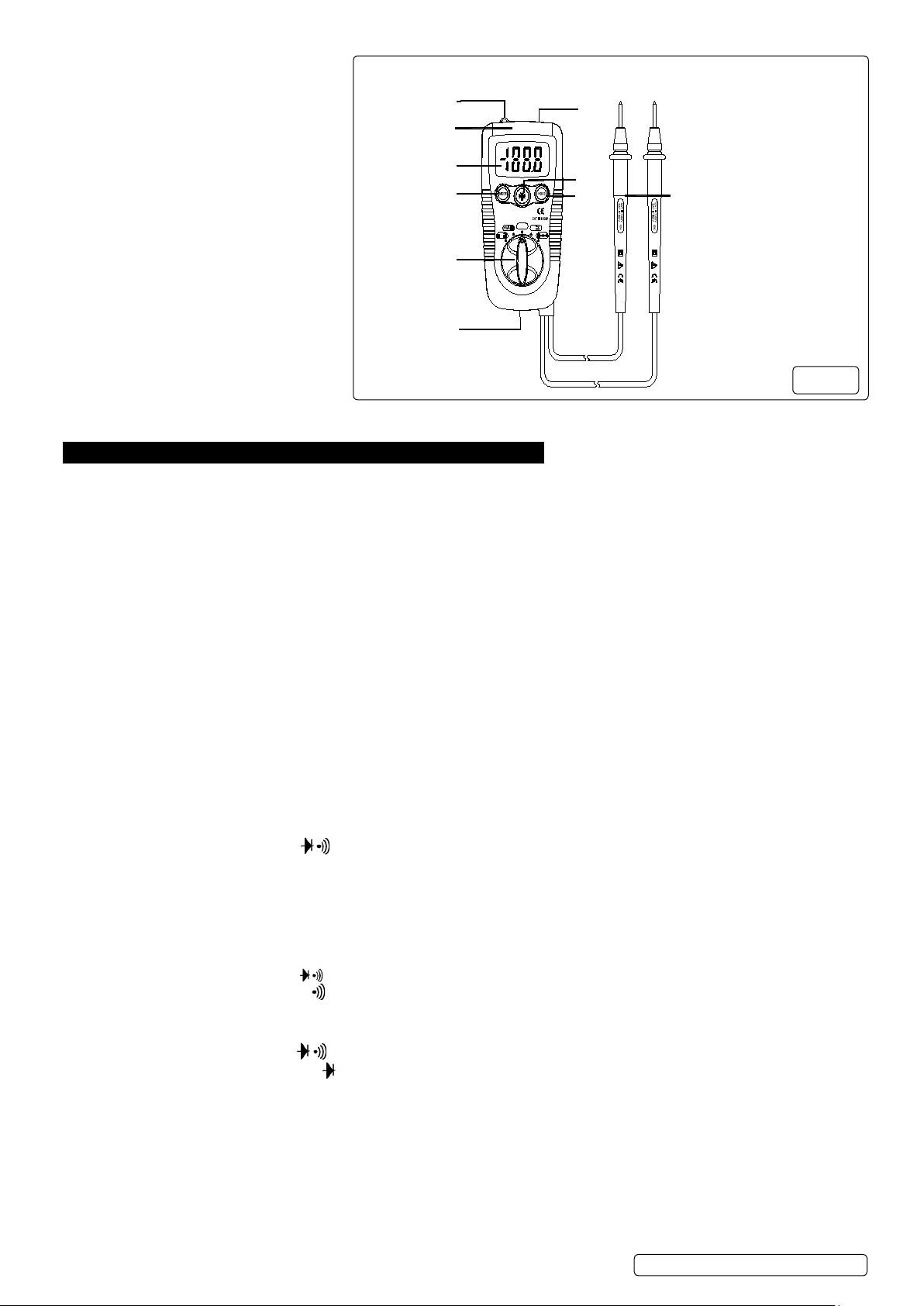
2. INTRODUCTION
Lightweight, auto-ranging digital multimeter with double moulded plastic housing and a 2000 counts LCD display. Features forward facing work
light, data hold and non-contact AC voltage detection. Conforms to EN 61010-1 CATIII 1000V / CAT IV 600V safety standard.
Measures: AC and DC Voltage, AC and DC Current, Resistance, Diode Test, Continuity Test.
3. SPECIFICATION
Model No ...............................................................................................................................................MM102
AC Voltage (Accuracy)...............................................................................2V, 20V (±1%), 200V, 600V (±2.3%)
DC Voltage (Accuracy)...............................................................200mV (±0.5%), 2V, 20V, 200V, 600V (±1.2%)
AC Current (Accuracy)........................................................................200µA, 2000µA, 20mA, 200mA (±2.5%)
DC Current (Accuracy)...........................................................................200µA, 2000µA, 20mA, 200mA (±2%)
Resistance (Accuracy)
Capacitance (Accuracy).................................................................................................................................No
Frequency (Accuracy)....................................................................................................................................No
Duty Cycle......................................................................................................................................................No
Continuity Audible................................................ ........................................................................................Yes
Diode Test..................................................................................................................................... ...............Yes
Transistor Test...............................................................................................................................................No
Hi- Impact Case.............................................................................................................................................No
Digits x Height.....................................................................................................................................4 x 14mm
Low Battery Indicator....................................................................................................................................Yes
Batteries (supplied)......................................................................................................................... 2 AAAx1.5V
Size (L x W x D)......................................................................................................................105 x 57 x 34mm
Weight........................................................................................................................................................160g
Conformity........................................................................................................................................EN61010-1
Non-Contact Voltage Detection VAC......................................................................................... .....100V - 600V
M
Original Language Version
© Jack Sealey Limited
Refer to
instructions
Electrical
shock
hazard

1. Non-contact AC voltage detector probe tip
2. Non-contact AC voltage indicator light
3. 3 1/2 Digit (2000 count)
4. MODE button
5. Function switch
6. Flashlight
7. Flashlight button
9. Battery Cover
10. Test leads
4. OPERATION
WARNING! Risk of electrocution. High voltage circuits, both AC and DC are dangerous and should be measured with great care.
Always turn the function switch to the off position when the meter is not in use.
4.1. AC/DC VOLTAGE MEASUREMENTS
8DO NOT measure DC/AC voltages if a motor on the circuit is being switched ON or OFF. Large voltage surges may occur that can
damage the meter.
4.1.1. Set the function switch to the green V position.
4.1.2. Press the MODE button to indicate “DC” or “AC” on the display.
4.1.3. Touch the black test probe tip to the negative side of the circuit.
4.1.4. Touch the red test probe tip to the positive side of the circuit.
4.1.5. Read the voltage in the display.
4.2. DC/AC CURRENT MEASUREMENTS
4.2.1. Set the function switch to the µA/mA position.
4.2.2. For current measurements up to 2000uA DC/AC, set the function switch to the mA position
4.2.3. Press the MODE button to indicate “DC” / “AC” on the display.
4.2.4. Remove power from the circuit under test, then open up the circuit at the point where you wish to measure current.
4.2.5. Touch the black test probe tip to the negative side of the circuit.
4.2.6. Touch the red test probe tip to the positive side of the circuit.
4.2.7. Apply power to the circuit.
Read the current in the display.
4.3. RESISTANCE MEASUREMENT
WARNING! To avoid electric shock, disconnect power to the unit under test and discharge all capacitors before taking any
resistance measurements. Remove the batteries and unplug the line cords.
4.3.1. position.
4.3.2.
4.3.3. Touch the test probe tips across the circuit or part under test. It is best to disconnect one side of the part under test so the rest of the
circuit will not interfere with the resistance reading.
4.3.4. Read the resistance in the display.
4.4. CONTINUITY CHECK
WARNING! To avoid electric shock, never measure continuity on circuits or wires that have voltage on them.
4.4.1.
4.4.2. Press the MODE button to indicate on the display
4.4.3. Touch the test probe tips to the circuit or wire you wish to check.
4.4.4.
4.5. DIODE TEST
4.5.1.
4.5.2. Press the MODE button to indicate on the display.
4.5.3. Touch the test probes to the diode under test. Forward voltage will typically indicate 0.400 to 0.700V. Reverse voltage will indicate
“OL”. Shorted devices will indicate near 0V and an open device will indicate “OL” in both polarities.
4.6. Non-Contact AC Voltage Measurements
WARNING! Risk of Electrocution. Before use, always test the Voltage Detector on a known live circuit to verify proper operation
4.6.1.
4.6.2. If AC voltage is present, the detector light will illuminate.
NOTE: The conductors in electrical cables are often twisted. For best results, move the non contact probe along a length of the
cable to assure the probe is in close proximity to the live conductor.
NOTE: The detector is designed with high sensitivity. Static electricity or other sources of energy may randomly operate the sensor.
This is normal operation.
5
6
2
4
3
1
PO
AU
O
T
OFF
ER
W
OFF
A
V
Ran
Auto
DMM
ing
g
8
9
7
10
M
Original Language Version
© Jack Sealey Limited

4.7. HOLD BUTTON
4.7.1. The Data Hold function allows the meter to “freeze” a measurement for later reference
4.7.2. Press the “DATA HOLD” button to “freeze” the display, the “HOLD” indicator will appear.
4.7.3. Press the “DATA HOLD” button to return to normal operation.
FLASHLIGHT
Press and hold the top button to turn the flashlight on. Release the button to turn the flashlight off.
4.9. AUTO POWER OFF
The auto off feature will turn the meter off after 15 minutes.
5. MAINTENANCE
WARNING! To avoid electric shock, disconnect the test leads from any source of voltage before removing the back cover or the battery
or fuse covers.
5.1. REPLACING THE BATTERY
5.1.1. Remove the bottom cover and secure the screw.
5.1.2. Replace old battery with two 1.5V AAA type batteries.
5.1.3. Replace the bottom cover and secure with the screw.
5.2. REPLACING THE FUSE
5.2.1. Disconnect the test leads from the meter.
5.2.2. Remove the test leads holder and top cover by removing screw.
5.2.3. Pull out the pcb Lift the centre circuit board straight up from the connectors to gain access to the fuse holders.
5.2.4. Remove the old fuse and install the new fuse into the holder. (Always use the correct size of fuse).
5.2.5. Align the board with the connects and gently press into place.
5.2.6. Replace and secure the cover.
WARNING! To avoid electric shock, do not use meter unless all covers are in place
M
Original Language Version
© Jack Sealey Limited
Sealey Group, Kempson Way, Suffolk Business Park, Bury St Edmunds, Suffolk. IP32 7AR
01284 757500 01284 703534 sales@sealey.co.uk www.sealey.co.uk
BATTERY REMOVAL SEE SECTION 5
Under the Waste Batteries and Accumulators Regulations 2009, Jack Sealey Ltd are required to inform potential purchasers of products
containing batteries (as defined within these regulations), that they are registered with Valpak’s registered compliance scheme.
Jack Sealey Ltd Batteries Producer Registration Number (BPRN) is BPRN00705.
Note: It is our policy to continually improve products and as such we reserve the right to alter data, specifications and component parts without prior
notice.
Important: No Liability is accepted for incorrect use of this product.
Warranty: Guarantee is 12 months from purchase date, proof of which is required for any claim.
ENVIRONMENT PROTECTION
Recycle unwanted materials instead of disposing of them as waste. All tools, accessories and packaging should be sorted, taken to
a recycling centre and disposed of in a manner which is compatible with the environment. When the product becomes completely
unserviceable and requires disposal, drain any fluids (if applicable) into approved containers and dispose of the product and fluids
according to local regulations.
Table of contents
Other Sealey Multimeter manuals

Sealey
Sealey MM20.V2 User manual

Sealey
Sealey MM402 User manual

Sealey
Sealey MM18 User manual

Sealey
Sealey MM18 User manual

Sealey
Sealey TM105 User manual

Sealey
Sealey MM24 User manual

Sealey
Sealey TA330 User manual

Sealey
Sealey TM102 User manual

Sealey
Sealey MM104 User manual

Sealey
Sealey Auto Service Series User manual

Sealey
Sealey TM104 User manual

Sealey
Sealey TM101 User manual

Sealey
Sealey MM104.V2 User manual

Sealey
Sealey TA202 User manual

Sealey
Sealey Professional MM19.V2 User manual

Sealey
Sealey TA311 User manual

Sealey
Sealey MM302.V2 User manual

Sealey
Sealey Professional MM20 User manual

Sealey
Sealey TM103 User manual

Sealey
Sealey TM100 User manual