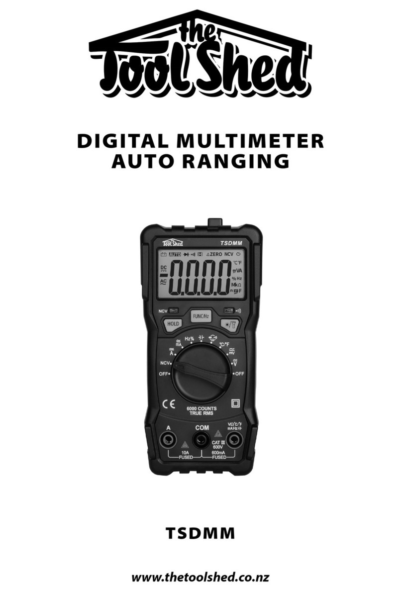
Tool Shed TSDCM User manual

23
OPERATION MANUAL OPERATION MANUAL
WWW.THETOOLSHED.CO.NZWWW.THETOOLSHED.CO.NZ
TABLE OF CONTENTS PRODUCT DETAILS
Product Model ToolShed Digital Clamp Multimeter
Product Code TSDCM
DISTRIBUTED BY:
Product Details 3
Specications 4
Display Symbols 5
Safety Guidelines 6
Operation 8
Technical Indicators 10
Maintenance 12
Note:
This manual is for your reference only. Due to the continuous improvement of
the ToolShed products, changes may be made at any time without obligation
or notice.
Warranty:
This product may be covered under The ToolShed warranty. For more information, see
our Terms & Conditions at www.thetoolshed.co.nz
Thank You
For the purchase of this ToolShed product. We try our hardest to supply customers like you
with the best quality products available, at the best price possible. We cant wait to continue
working together in the future.
Please contact us for any servicing, replacement parts, or questions you might have about
your ToolShed product by visiting our website, or calling: 0800 948 665.

45
OPERATION MANUAL OPERATION MANUAL
WWW.THETOOLSHED.CO.NZWWW.THETOOLSHED.CO.NZ
SPECIFICATIONS
CONTENTS
DISPLAY SYMBOLS
Maximum Input Voltage AC & DC: 600 Volts
Working Height Up to 2000 metres
Display LCD
Sampling Time Approx. 3 times/second
Automatic Shut Down Time 15 Minutes
Power Supply 2 X 1.5 AAA Battery
Dimensions (LxWxH) 165 x 56 x 31 mm
Net Weight (Including Battery) 140 Grams
Selection
Reading Hold (Short Press)
Backlight (Long Press)
Clear the Low Number of the DC
Connect the Input Terminal to
the Black Test Pen.
AC/DC Voltage, Resistance,
Capacitance, Diode, Continuity
Measurement, Temperature
(Connect with the Red Test Pen)
Meter
Test Pen Wire
1.5 X2 AAA Battery
Thermocouple
Custom Carry Bag
Battery Under Voltage / Low Battery
Automatic Shutdown Function
Negative Input Polarity
AC Voltage
DC Voltage
Continuity Test
Diode Test
Non-Contact AC Voltage Detection
Reading Hold
Capacitance Measurement
Resistance Measurement
Temperature Measurement
Current Measurement
Clear the AC/DC
Description of Keys Description of the Input Socket

67
OPERATION MANUAL OPERATION MANUAL
WWW.THETOOLSHED.CO.NZWWW.THETOOLSHED.CO.NZ
SAFETY GUIDELINES SAFETY GUIDELINES
Multimeter Specic Safety
While In UseService
Product Overview
• Have your tools and machinery serviced
at The ToolShed with ToolShed replace-
ment parts. This will ensure that the safety
of the power tool or machine is maintained.
• This instrument is a digital AC/DC miniature
clamp meter, highly reliable, precise, and
easy to carry. It features an automatic range,
reading hold, temperature measurement,
automatic shutdown, backlight, full range
overload protection, and battery under –
voltage indication. Whether this meter is
used by professionals, factories, schools, or
enthusiasts, it is an ideal multi-functional
instrument. The meter can be used for the
test of AC/DC, AC/DC Voltage, resistance,
capacitance, diode, continuity, temperature,
or NCV test.
When using the meter, the user must follow
standard safety rules:
• After transportation, always check to ensure
that the meter is not damaged in any way.
• Check if the test pen remains in good condi-
tion and is undamaged.
• Attention should be paid when using the
meter around bare conductors or buses,
in order to prevent electric shock or arc
discharge, which may cause injury.
• The user should always adopt the prove-
test-prove method when using this or any
multi meter. Prove the meter works on a
known live circuit; test the circuit you want
to test, then re-prove the meter works on
a know circuit to ensure the test results are
accurate.
• A preliminary check should always be
performed to ensure the meter outer shell is
not damaged, or whether the insulation layer
of the test pen is undamaged in any way, and
whether the range of gear is correct for your
needs.
• Do not exceed the indicated minimum and
maximum values of each measurement
range, or switch the gear being used during
measuring.
• Do not touch the top of the test pen (the
metal section) when the meter is connected
to the tested circuit as this could cause
personal shock or injury.
• If the measured voltage is higher than 60V
DC or 30V AC (valid value), be aware of
electric shock, and avoid placing your nger
anywhere but the protective sheath of the
test pen.
• Do not use the multimeter when the voltage
from the input terminal and the ground is
greater than 600 Volts.
• Ensure you remove the test pen from the
tested circuit before the rotary switch
changes the measurement function.
• Do not store or use the meter under direct
sunlight, in high temperature, or high
humidity.
WARNING
WARNING
The warnings and precautions
discussed in this manual cannot cover
all possible conditions and situations
that may occur. It must be under stood
by the operator that common sense
and caution are factors which cannot
be built into this product, but must be
supplied by the operator.
Attention should be paid when using
this meter. Improper operation may
cause electric shock ,or damage to
the meter or user. Please read the
instructions before use, and use the
meter according to these instructions.

89
OPERATION MANUAL OPERATION MANUAL
WWW.THETOOLSHED.CO.NZWWW.THETOOLSHED.CO.NZ
OPERATION OPERATION
Reading Hold/Backlight AC/DC Measurement
Automatic Shutdown
Measurement Guide Measurement of Resistance/
Diode/Continuity/Capacitance
Measuring AC/DC Voltage
NCV Test
• The reading hold mode can hold the current
reading on the display by short pressing
the HOLD key. Short press the HOLD key to
switch the measuring function, or to exit the
reading hold mode.
• Press the key for 2 seconds to turn the
backlight on or o.
• Turn the range switch to Afor current meas-
urement, and press the SEL key to switch to
AC or DC according to the current job.
• Hold the trigger to open the meter jaws, and
clamp a wire of the line to be measured in
the centre of the clamp head.
• When both jaws are completely closed, the
meter will display the measured current
value.
• Only a single wire can be clamped for
measurement at one time. It is impossible to
accurately measure current from two wires
simultaneously.
• The maximum measurable current is 100A.
• Resistance Measurement; press the SEL
key to M, which is the automatic switch for
automatic range k/M measurement.
• Continuity Measurement; If the resistance
of the tested object is less than approx. 50Ω,
the indicating light (red light) of the meter
will remain on, and the buzzer will sound
continuously.
• Diode Measurement; Press SEL key to
• When measuring normal diode, the meter
will display the forward voltage drop of the
diode — Normal 0.5V to 0.8V forward voltage
drop.
• If the meter is not used within 15 minutes
after starting, the unit will shut down auto-
matically and enter sleep mode.
• Press the HOLD button under the Automatic
Shutdown mode to turn the meter on.
• This meter adopts automatic range detec-
tion. When measuring AC/DC voltage,
resistance, and capacitance, the values will
automatically be displayed on the screen.
• Turn the switch to the setting, press the
SEL key to choose corresponding functions.
Plug the red and black test pens to the INPUT
socket and COM socket respectively.
• Capacitance Measurement; the capaci-
tance range of the meter is 200nF, 2uF, 20uF,
200uF, 2000uF.
• Press the SEL key to nF; which is the auto-
matic switch for automatic range nF/F meas-
urements.
• Turn the rotary switch to the posi-
tion, and short press the SEL key to switch
between AC or DC voltage.
• Plug both the black and red test pen to the
COM socket and INPUT socket respectively.
• Connect the test pen to the circuit that you
want to test.
• Switch to the NCV key and move the clamp
head close to the conductor. By detecting
the signal strength, the meter judges the
strength of the tested voltage. The screen
then displays ----- red indicating light, and
the buzzer will emit alarm sounds of dierent
frequencies.
NOTE
NOTE
NOTE
NOTE
In the mV range of DC and AC, even if
there is no test pen input or connection,
the meter will display a numerical
value. In this case, if the “V” and “COM”
terminals are short-circuited, the meter
will display zero, which is normal.
The AC/DC voltage range of this meter:
Gear 2V, 20V, 200V, 600V
The actual value of the resistance may
dier from that measured on the circuit.
When the meter measures an open
circuit, or the measured resistance value
is too big, the screen will display “OL”
(Overload) which means the measured
value is beyond the range.
To ensure the readings are accurate,
short press the ZERO key under the
DC current mode, which will clear
the low number of the DC caused by
electromagnetic interference.
The Capacitor should be fully
discharged before measuring the
capacitance. Therefore it may take
some time to stabilise the reading, as
the capacitor needs to be charged.
Temperature Measurement
• When setting the range, switch to the posi-
tion, the meter will automatically measure
and show the current environmental temper-
ature. Pressing the SEL key will switch to °F.
• To measure the temperature of an object
or liquid, insert the red plug of the K-Type
thermocouple into the INPUT socket and the
black plug into the COM socket, then ensure
the thermocouple probe comes into contact
with the test area.

10 11
OPERATION MANUAL OPERATION MANUAL
WWW.THETOOLSHED.CO.NZWWW.THETOOLSHED.CO.NZ
TECHNICAL INDICATORS TECHNICAL INDICATORS
Range Resolution
2V 0.001V
20V 0.01V
200V 0.1V
600V 0.1V
Range Resolution
2A 0.001A
20A 0.01A
100A 0.1A
Range Resolution
0.15V—2.5V 0.001 Volts
Range Resolution
100Ω 1.0Ω
Range Resolution
2V 0.001V
20V 0.01V
200V 0.1V
600V 0.1V
Range Resolution
2A 0.001A
20A 0.01A
100A 0.1A
Range Resolution
200Ω 0.1Ω
2KΩ 0.001KΩ
20KΩ 0.01KΩ
200KΩ 0.1KΩ
2MΩ 0.001MΩ
20MΩ 0.01MΩ
Range Resolution
-20–1000°C 1°C
-4–1832°F 1°F
Range Resolution
200nF 0.1nF
2uF 0.001uF
20uF 0.01uF
200uF 0.1uF
2000uF 0.001uF
DC Voltage AC CurrentDiode Test
Buzzer Continuity
AC Voltage
DC Current
Resistance
Temperature
Capacitance
Accuracy: ± 0.5% of Reading + 3 Digits.
Input Impedance: 10MΩ;
Maximum Input Voltage: 600 Volts.
Accuracy: ± 2.5–3.0% of Reading + 6 Digits.
Maximum Input Current: 100 Amps.
Frequency Range: 40–100 Hz.
Test Condition: Forward DC: Approx. 1mA;
Open Circuit Voltage: Approx. 2.5 Volts.
Display the approximate value of the diode
forward voltage.
Overload Protection: 250 Volts.
Description: If resistance is less that 50Ω the
buzzer will sound.
Test Condition: Open circuit voltage: 1V.
Overload Protection: 250 Volts.
Accuracy: ± 1.0% of Reading + 3 Digits.
Input Impedance: 10MΩ;
Maximum Input Voltage: 600 Volts.
Accuracy: ± 2.5–3.0% of Reading + 6 Digits.
Accuracy: ± 0.8% of Reading + 3 Digits.
Overload Protection: 250 Volts;
Open Circuit Voltage: 1.2 Volts.
Accuracy: ± 2.0% of Reading + 2–4 Digits.
Overload Protection: 250 Volts.
Accuracy: ± 3.5% of Reading + 15 Digits.
Overload Protection: 250 Volts.

12
OPERATION MANUAL
WWW.THETOOLSHED.CO.NZ
MAINTENANCE
• Non-authorised servicemen should not open the unit to adjust or repair the Multimeter.
• In order to avoid electric shock caused by incorrect reading, the battery should be replaced
immediately when the instrument displays
• When the Multimeter is not in use, ensure it is always switched OFF.
• If the multimeter is not to be used for extended periods of time, the batteries should be taken
out to prevent the battery acid or liquid from leaking out and damage the unit.
• After one year the multimeter should always be re-calibrated under the conditions where the
temperature is between 18°C–28°C, and the relative humidity is lower than 75%.
Battery Replacement
To replace the battery please follow these steps:
• Turn o the power supply of the meter.
• Remove all the test lines from the measuring
circuit.
• Use a screwdriver to remove the screw that
xes the battery cover on the back of the
meter.
• Remove the Battery Cover.
• Remove the old batteries.
• Replace with 2 x 1.5V AAA batteries.
• Place the battery cover back on the unit and
use the screwdriver to tighten the screws
back into place.
Table of contents
Other Tool Shed Multimeter manuals