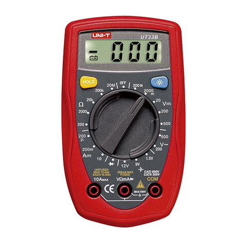
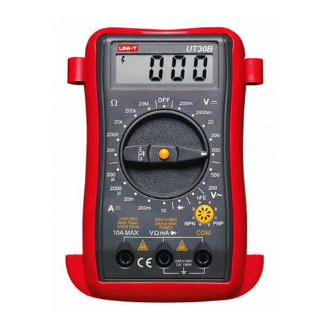
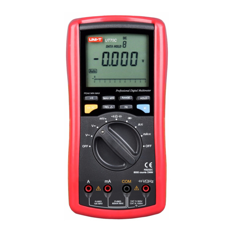
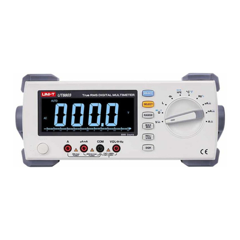
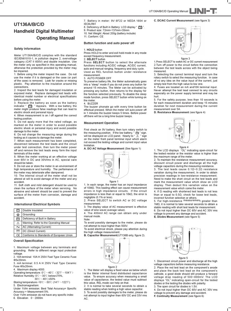
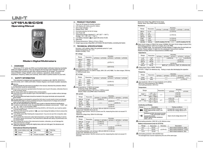
Unit UT39B User manual

®
UT39B
MANUAL
HANDLEIDING
NOTICES

®
1 2
UT39B
• Illustrations and tables 1
• English Operating Manual 5
• Nederlandse handleiding 13
• Notices français 21
Fig 2: Display symbolsFig 1: The meter’s structure Fig 3: Voltage measurement
Fig 5: Resistance MeasurementFig 4: Current Measurement Fig 6: Capacitance Measurement

Model: UT39B OPERATING MANUAL
12
Fig 7:Transistor Test Fig 8: Replacing the battery Fig 9: Replacing the fuses
Accuracy: +/-(a% reading + b digits) - guaranteed for 1 year
Operating temperature: 23°C +/- 5%
Relative Humidity: < 75%
Range Resolution Accuracy
200mV 100µV
+/-(0.5%+1)
2V 1mV
20V 10mV
200V 100mV
1000V 1V +/-(0.8%+2)
Range Resolution Accuracy
2V 1mV
+/-(0.8%+3)20V 10mV
200V 100mV
750V 1V +/-(1.2%+3)
Input impedance: 10MW
Overload protection: 250VAC (200mV range) - 1000V DC / 750V AC (all other ranges)
Input impedance: 10MW
Maximum input voltage: 750V AC
Displays effective value of sine wave.
Overload protection: 1000VDC or 750VAC

Range Resolution Accuracy Overload
protection
20µA 0,01µA +/-(2%+5)
Fuse: 0.315A / 250V
Fast type 5x20mm
2mA 1µA +/-(0.8%+1)
20mA 10µA
200mA 100µA +/-(1.5%+1)
10A 10mA +/-(2%+5) Unfused
Range Resolution Accuracy Overload
protection
2mA 1µA +/-(1.0%+3) Fuse: 0.5A /250V
Fast type: 5x20mm
200mA 100µA +/-(1.8%+3)
10A 10mA +/-(3.0%+5) Unfused
Range Resolution Accuracy Overload
protection
200W0.1W+/-(0.8%+3)
250V DC or AC rms
2kW1W
+/-(0.8%+1)20kW10W
2MW1kW
20MW10kW+/-(1.0%+2)
200MW100kW+/-(5%+10)
When <5A: continuous measurement is allowed
When >5A: continuous measurement less than 10 seconds at an interval more than 15 minutes
When <5A: continuous measurement is allowed
When >5A: continuous measurement less than 10 seconds at an interval more than 15 minutes
Displays effective value of sine wave
Measurement voltage drop: Full range at 200mV
Open circuit voltage: At 200MW: approx. 3V
Other range: <= 700mV
®
3 4

34
Range Resolution Remark
0.001V Open circuit voltage around 2.8V
A good junction drops between 0.5V ~ 0.8V
1WThe buzzer does not sound if the resistance of a
circuit is below 70W.
The buzzer sounds continuously if the circuit is in
a good condition with resistance below 10W
Range Resolution Accuracy
2nF 1pF
+/-(4%+3)200nF 0.1nF
20µF 10nF
Testing signal: approx 400Hz, 40mV rms
Range Resolution Remark
hFe 1bVce=3V Ibo=10µA 1000bMAX
Model: UT39B OPERATING MANUAL

• Overview 6
•
• Safety information 6
• The meter’s structure 7
• Functional buttons 7
• Display symbols 8
• Measurement operation 8
A. AC/DC voltage measurement 8
B. AC/DC current measurement 9
C. Resistance measurement 9
D. Capacitance measurement 10
E. Diode test 10
F. Continuity test 11
G. Transistor test 11
• Sleep mode 12
• Maintenance and service 12
A. General service and maintenance 12
B. Replacing the battery 12
C. Replacing the fuses 12
®
5 6

56
This operating manual covers information on safety and cautions. Please read the relevant informa-
tion carefully and observe all the Warnings and Notes strictly.
Measuring range and accuracy - seep page 1-3
1. 10A terminal: un-fused.
2. µA mA terminal: 0.315 A H 250V Fast Type Ceramic Fuse 5x20mm.
3. Range: Manual ranging
4. Maximum display: 1999 or 3 1/2 digit.
5. Measurement speed: Updates 2 ~3 times/second
6. Temperature: Operating: 0°C~40°C
Storage: 30°C~40°C : £50%
7. Battery type: 9V 6F22 or NEDA 1604 or IEC6LR6
8. Safety compliances: IEC61010 CATI 1000V CATII 600V
Overvoltage and double insulation standard.
9. Conform: CE
Meter UT39B complies with the standard IEC/EN61010-1, in pollution degree 2, overvoltage cat-
egory (CAT I 1000V, Cat II 600V) and double insulation.
To avoid possible electic shock or personal injury, and to avoid possible damage to the meter or to
the equipment under test, adhere to the following rules:
• Before using the meter inspect the case. Do not use the meter if it is damaged or the case (or
part of the case) is removed. Look for cracks or missing plastic. Pay attention to the insulation
around the connections.
• Inspect the test leads for damaged insulation or exposed metal. Replace damaged test leads
• The internal circuit of the meter shall not be altered at will to avoid damage of the meter and
any accident.
• The meter is suitable for indoor use.
• Replace the battery as soon as the battery indicator “ ” appears. With a low battery, the
meter might produce false readings that can lead to electric shock and personal injury.
• Do not apply more than the rated voltage, as marked on the Meter, between the terminals or
between any terminal and the grounding.
• The rotary switch should be placed in the right position and not any changeover of range shall
be made during measurement is conducted to prevent damage of the Meter.
Model: UT39B OPERATING MANUAL

®
7 8
• When the Meter working at an effective voltage over 60V in DC or 30V rms in AC, special care
should be taken for there is danger of electric shock.
• Do not use or store the Meter in an environment of high temperature; humidity, explosive,
dampened.
•
• Disconnect circuit power and discharge all high-voltage capacitors before testing resistance,
continuity, diodes and current.
• Before measuring current, check the Meter fuses and turn off power to circuit before connect-
ing the Meter to the circuit.
1. LCD Display
2. Data hold button
3. Transistor jack
4. COM input terminal
5. Other input terminals
6. mA input terminal
7. 10A input terminal
8. Capacitance jack
9. Rotary switch
10. Power
11. POWER button (yellow)
ON/OFF switch
12. HOLD button (blue)
Press HOLD to enter and exit hold mode.The symbol H is shown on the display when value is
hold.

78
1. H Data hold is active
2. - Indicates negative reading
3. Battery is low.To avoid false readings, replace the battery as soon as this
indicator appears.
4. hFE Unit of transistor
5. °C Centigrade temperature
6. Test of diode
7. Continuity buzzer
8. Dangerous voltages
A. DC/ AC Voltage Measurement
To measure voltage, connect the meter as follows:
1. Insert the red test lead into the VWterminal and the black test lead into the COM terminal.
2. Set the rotary switch to an appropriate measurement position in V--range for DC or V~ for AC.
When the value is unknown always start from the max range 1000 V.
3. Connect the test leads across with the object being measured. The measured value shows on
the display.
Note
• Displays ‘1’ selected range is overload; it is required to select a higher range in order to obtain
a correct reading.
• In each range, the Meter has an input impedance of approx.10MW. This loading effect can
cause measurement errors in high impedance circuits. If the circuit impedance is less than or
equal to 10kW, the error is negligible (0.1% or less).
To avoid possibly damages to the meter, please do not attempt to input higher than 1000V or 750V
rms.
Model: UT39B OPERATING MANUAL
®
9 10
B. DC/AC Current Measurement
• Never attempt an in-circuit current measurement where the voltage between terminals and
ground is greater than 60V DC or 30V rms.
• If the fuse burns out during measurement, the Meter may be damaged or the operator himself
may be hurt. Use proper terminals, function, and range for the measurement.
• When the testing leads are connected to the current terminals, do not parallel them across any
circuit.
• Measuring time for current should be less than 10 sec and interval between measurement
should be at least 15 minutes.
To measure current, do the following:
1. Turn off power to the circuit. Discharge all high-voltage capacitors.
2. Insert the red test lead into the A or mA terminal and the black test lead into the COM termi-
nal.
3. Set the rotary switch to an appropriate measurement position A = for DC or A~ for AC. When
the value is unknown always start from the max range 20 A.
4. Break the current path to be tested. Connect the red test lead to the more positive side of the
break and the black test lead to the more negative side of the break.
5. Turn on power to the circuit.The measured value shows on the display.
If the value to be measured is unknown, use the maximum measurement position and reduce the
range step by step until a satisfactory reading is obtained.
C. Resistance Measurement
To avoid damages tot the meter or to other devices under test, disconnect circuit power and dis-
charge all the high voltage capacitors before measuring resistance.
To measure connect the meter as follows:
1. Insert the red test lead into the VWterminal and the black test lead into the COM terminal.
2. Set the rotary switch to an appropriate measurement position Wrange.
3. Connect the test leads across with the object being measured. The measured value shows on
the display.
For high resistance measurement (>1MW) it is normal to take several seconds to obtain a stable
reading.

910
Note:
• The test leads can add 0.1Wto 0.3Wof error to the resistance measurement.To obtain preci-
sion readings in low-resistance measurement, that is the range of 200W, short-circuit the input
terminals beforehand and record the reading obtained.This is the additional resistance from
the test lead, which need to be deducted from the measured value.
• The LCD display indicates “1” for open circuit or if the tested resistor is of higher value than
the maximum range of the meter.
D. Capacitance Measurement
To avoid damage to the meter, disconnect circuit power and discharge all high voltage capaci-
discharged.
To measure capacity, connect the meter as below:
1. Insert the capacitor to be tested into the capacitance jack.
2. Set the rotary switch to an appropriate measurement position in the F range.
3. Connect the test leads across with the object being measured. The measured value shows on
the display.
Note:
• For testing a capacitor with polarity, connect the red test lead to the anode and the black test
lead to the cathode.
• When the tested capacitor is shorted or the value is overloaded, the LCD displays ‘1’.
• To minimize the measurement error, the testing lead should be as short as possible.
• It is normal to take a longer time when testing a>10µF high capacitor value.
E. Diode measurement
Disconnect circuit power and discharge all the high voltage capacitors before measuring diodes. Do
not attempt to input voltages higher than DC 60V and AC 30V rms to prevent any damage and to
avoid harms to yourself.
The diode test sends a current through the semiconductor junction, and then measures the voltage
drop across the junction.A good silicon junction drops between 0.5V and 0.8V.
To test out a diode, connect the meter as follows:
1. Insert the red test leasd into the Wterminal and the black test lead into the COM terminal.
2. Set the rotary switch to diode test.
3. For forward voltage drop readings on any semiconductor component, place the red test lead
on the component’s anode and the black test lead on the component’s cathode. The measured
value shows on the display.
Model: UT39B OPERATING MANUAL
®
11 12
• In a circuit, a good diode should still produce a forward voltage drop reading of 500 ~ 800mV.
However, the revers voltage drop reading can vary depending on the resistance of other path-
ways between both tips.
• Connect the test leads to the proper terminals as said above to avoid error display. The LCD
will display “1” indicating the diode being tested is open or polarity is reversed.The unit of the
diode is Volt, displaying the forward voltage drop readings
• The open circuit voltage is arount 3V
F. Continuity Measurement
Disconnect circuit power and discharge all the high voltage capacitors before testing continuity. Do
not attempt to input voltages higher than DC 60V and AC 30V rms to prevent any damage and to
avoid harms to yourself.
To test for continuity, connect the meter as below:
1. Insert the red test lead into the Wterminal and the black test lead into the COM terminal.
2. Set the rotary switch to the continuity test function
3. The buzzer sounds continuously if the resistor to be tested is < 10W. The busser does not
sound if the resistor to be tested is > 35W. The measured value shows on the display and the
unit is W.
G. Transistor Test
Do not input voltages higher than DC 60V or AC 30V to prevent any damage and accident.
To measure transistor, connect the meter as follows:
1. Set the rotary switch to hFE
2. Insert the NPN or PNP transistor to be tested into the transistor jack.
3. The measured nearest value shows on the display
To preserve battery life, the meter automatically turns off if you do not turn the rotary switch or
press any button for around 15 minutes. To activate meter, press power for two times.

1112
relevant calibration, performance test and service information.
A. General Service and Maintenance
• Periodically wipe the case with a damp cloth and mild detergent. Do not use abrasives or sol-
vents. Clean the terminals with cotton bars with detergent, as dirt or moisture in the terminals
can affect readings.
• Turn of the power of the meter when it is not in use and take out the battery if it is not used
for a long time.
• Any abnormal on the meter, stop use the meter and return to service center.
•
B. Replacing the battery
The battery need to be replaced by a new battery as soon as the battery indicator appears.
To replace the meter’s battery:
1. Turn the meter off and remove all connections from the terminals.
2. Remove the screw from the battery compartment.
3. Remove the battery and replace it with a new 9V battery (6F22 or NEDA 1604 / IEC6LR61)
and close the battery compartment.
C. Replacing the fuses
1. Turn the meter off, remove the test leads and the holster from the meter.
2. Remove the screws from the battery compartment and 2 other screws from the case bottom.
Separate case and bottom.
3. Gently remove the fuse and replace it by an identical one:
A mA range F1 Fuse 5×20mm, F 0.315 A H 250V
4. Rejoin the case bottom and case top and rejoin the holster.
Replacement of the fuses is seldom required. Burning a fuse always results from improper opera-
tion.
Model: UT39B OPERATING MANUAL
®
13 14
• Overzicht 14
•
• Veiligheidsinformatie 14
• Structuur van het toestel 15
• Functietoetsen 15
• Metingen
A. Gelijk- en wisselspanningsmeting 16
B. Gelijk- en wisselstroommeting 17
C. Weerstandsmeting 17
D. Capaciteitsmeting 18
E. Diodetest 18
F. Continuiteitstest 19
G. Transistor test 19
• Slaap stand 19
• Onderhoud en service
A. Algemene service en onderhoud 20
B. Vervangen van de batterij 20
C. Vervangen van de zekeringen 20

1314
Model: UT39B HANDLEIDING
Deze handleiding bevat alle veiligheidsvoorschriften en voorzorgsmaatregelen. Gelieve de handlei-
ding aandachtig te lezen en rekening te houden met alle waarschuwingen en notities.
Voor meetbereiken en nauwkeurigheid verwijzen we naar de tabels op p 1-3 van deze handleiding.
1. 10A meetbus: niet beveiligd door een zekering
2. µA mA meetbus: 0.315 A H 250V snelle zekering 5x20mm.
3. Manueel bereik
4. Maximum display: 1999 of 3 1/2 digit
5. Meetsnelheid: Update 2 ~3 x / seconde
6. Werktemperatuur: 0°C~40°C (32°F ~104°F)
7. Opslag temperatuur: -10°C ~50°C (14°F ~122°F)
8. Batterij in meter: 9V 6F22 of NEDA 1604 of IEC6LR6
9. Veiligheidsnormen: IEC61010 CATIII 1000V CATIV 600V
overspanning en dubbele isolatie standaard.
10. Conform: CE
De UT39B multimeter voldoet aan de normen IEC/EN61010-1, vervuilingsgraad 2, overspanning
categorie (CAT I 1000V en CAT II 600V) en dubbele isolatie. Gebruik de meter alleen als omschre-
ven in deze handleiding, om beschadiging van het toestel te voorkomen.
• Inspecteer de behuizing van het meettoestel voor gebruik. Maak geen gebruik van het toestel
wanneer deze beschadigd is of een deel van de behuizing ontbreekt. Kijk het toestel na op
scheuren of ontbrekend plastic.
• Inspecteer de isolatie van de meetsnoeren. Vervang beschadigde meetsnoeren onmiddellijk
wanneer de beschadiging wordt vastgesteld door een identiek paar meetsnoeren voor het
meettoestel wordt in gebruik genomen.
• Vervang de batterij wanneer de indicator voor lage batterijspanning op het LCD scherm ver-
schijnt: “ ”. Een lage batterij kan foute metingen als resultaat hebben, wat op zijn beurt
kan leiden tot elektrische schokken of kwetsuren.
• Het toestel is enkel geschikt voor binnenshuis gebruik.
• Het interne circuit van de meter mag niet worden gewijzigd, ter voorkoming van ongevallen of
schade.
• Bewaar de meter niet in een vochtige omgeving of in te hoge temperaturen. De prestaties van
het meettoestel kunnen hierdoor verslechteren.
• Schakel het te meten circuit steeds uit en ontlaad alle capaciteiten alvorens het testen van
weerstand, continuiteit en diode te starten.

®
15 16
• Breng niet meer dan de toegestane spanning aan, zoals weergegeven op het meettoestel, om
een mogelijk elektrische schok, kwetsuren of schade aan het toestel te vermijden
• Zet de draaischakelaar voor een meting in de juiste positie en bedien de draaischakelaar niet
gedurende een meting, ter voorkoming van een gevaarlijke situatie of schade aan het meet-
toestel.
• Wanneer de multimeter gebruikt wordt op een spanning van 60V DC en 30Vrms in AC, is extra
voorzichtigheid aanbevolen.
• Ontkoppel de testsnoeren van het te meten circuit zodra een meting is uitgevoerd. Schakel
vervolgens het toestel uit.
• Reinig de meter steeds met een zachte doek en een mild schoonmaakmiddel. Gebruik geen
agressief middel of oplosmiddel om schade aan het toestel te voorkomen.
1. LCD Display
2. Data hold functie toets
3. Transistor jack
4. COM ingangsbus
5. Andere ingangsbussen
6. mA ingangsbus
7. 10A ingangsbus
8. Capaciteit jack
9. Draaiknop
10. AAN/UIT toets
1. POWER toets
Druk deze toets om het toestel aan en uit te schakelen.
2. HOLD toets
Druk de HOLD toets om de HOLD functie in of uit te schakelen. Het symbool H wordt weer-
geven op het display.

1516
Model: UT39B HANDLEIDING
1. H Data hold is ingeschakeld
2. - Wordt weergegeven bij een negatieve uitlezing
3. Batterij is zwak. Om verkeerde uitlezingen te voorkomen, is het aangeraden om
de batterij onmiddellijk te vervangen wanneer dit symbool verschijnt.
4. hFE Transistortest
5. °C Graden celsius
6. Diodetest
7. Continuiteits zoemer
8. Gevaarlijke voltage
A. DC/ AC SpanningsMeting
Om voltage te meten, dient het toestel als volgt verbonden te worden:
1. Verbind het rode testsnoer met de V ingangsbus en het zwarte met de COM bus.
2. Zet de draaischakelaar op Voltage. V= voor DC meting,V~voor AC meting. Wanneer de te
meten waarde niet gekend is, start bij het hoogste bereik (1000V)
3. Verbind de testsnoeren parallel met het te meten circuit. De gemeten waarde
verschijnt op het display. Bij AC meting is dit de effectieve waarde van de sinusgolf of de
gemiddelde waarde.
Note
• Als het display de waarde ‘1’ aangeeft, moet men naar een hoger bereik overschakelen om
een juiste uitlezing te bekomen.
• In elk bereik is de ingangsimpedantie ongeveer 10MW. Deze impedantie kan de meetwaarde
beïnvloeden in circuits met een hoge impedantie. Bij circuits met een impedantie kleiner of
gelijk aan 10kW, is de foutmarge verwaarloosbaar (0.1% of minder).
Om mogelijk schade aan het toestel te voorkomen, is het aangeraden geen spanningen te meten
hoger dan 1000V of 750V rms.

®
17 18
B. DC/AC Stroommeting
• Geen stroommetingen uitvoeren, wanneer de spanning tussen de terminals meer dan 60V DC
of 30V rms bedraagt.
• De mA en 10A ingang zijn beveiligd met zekeringen. Als een zekering doorbrandt tijdens de
meting, kan de meter beschadigd worden of riskeert u zelf blessures.
• Om veiligheidsredenen, beperk de meting tot minder dan 10 seconden bij metingen hoger dan
5A. Wacht ook 15 minuten alvorens de volgende stroommeting boven 5A uit te voeren.
Op een stroommeting uit te voeren, volg de volgende stappen:
1. Schakel de stroom uit en ontlaad alle hoogspanningscapaciteiten.
2. Verbind het rode testsnoer met de A of mA ingangsbus en het zwarte testsnoer met de COM
ingangsbus.
3. Plaats de draaiknop op de juiste waarde A= voor DC en A~ voor AC. Wanneer u geen idee
heeft van het juiste bereik, start de meting in het hoogste bereik en verlaag stap voor stap tot
de juiste uitlezing wordt verkregen.
4. Verbind de meetsnoeren in serie met het te meten circuit. De gemeten waarde
verschijnt op het display.
C. Weerstandsmeting
Om de nauwkeurigheid van weerstandsmetingen te vrijwaren, schakel de voeding uit en ontlaad
alle condensatoren voor de meting te starten.
Om weerstand te meten, volg de volgende stappen
1. Verbind het rode testsnoer met de Wingangsbus en het zwarte met de COM ingangsbus.
2. Plaats de draaiknop in het juiste bereik van de Wmeting.
3. Verbind de testsnoeren parallel met het te meten circuit. De gemeten waarde verschijnt op het
display. To measure connect the meter as follows:
• De testsnoeren zorgen voor verhoging van de weerstandswaarde met 0.2W~0.5W. Bij lage
weerstandsmetingen dient men de weerstandswaarde van de meetsnoeren af te trekken van
de gemeten weerstandswaarde.
• Bij hoge weerstandswaarden is het normaal dat het enige tijd duurt alvorens een stabiele
waarde wordt bekomen.
• Als het LCD display de indicatie “1” aanduidt, betekent dit dat men een open circuit aan het
meten is of een weerstandswaarde die hoger is dan het maximale bereik van het toestel.

1718
Model: UT39B HANDLEIDING
D. Capaciteitsmeting
Om schade aan de meter te voorkomen, schakel het te meten circuit uit en ontlaadt alle hoogspan-
Verbindt de meter als volgt om capaciteit te meten:
1. Plaats de condensator in de capaciteitsbus.
2. Plaats de draaiknop in het juiste bereik van de F functie.
3. Verbindt de testsnoeren parallel met het te meten object. De gemeten waarde verschijnt op het
display.
• Wanneer de capaciteit is kortgesloten of de waarde is groter dan het bereik van de multimeter,
zal het display de waarde ‘1’ weergeven.
• Om een gepolariseerde condensator te testen, verbindt het rode test snoer met de anode en
het zwarte met de kathode.
• Het is normaal dat het enige tijd duurt om een stabiele waarde te verkrijgen bij een hoge
capaciteitswaarde (>10µF)
• Om de foutmarge zo klein mogelijk te houden is het aangeraden om met zo kort mogelijke
testsnoeren de meting uit te voeren.
E. Diodetest
Schakel de stroom van het te testen circuit uit en ontlaadt alle hoogspannings condensatoren, om
schade te voorkomen aan het meettoestel of te testen circuit. Het is aan te raden geen metingen uit
te voeren bij spanningen hoger dan DC 60V of AC 30V.
Een diodetest stuurt een stroom door de halfgeleider junctie, en meet vervolgens de spanningsval
over de junctie. A goede silicium junctie heeft een spanningsval tussen 0.5V en 0.8V.
Om een diode te testen, volg de volgende stappen:
1. Steek het rode meetsnoer in de Wingangsbus en het zwarte meetsnoer in de COM meetbus.
2. Plaats de draaiknop in op het diode bereik.
3. Vervolgens verbindt u het rode meetsnoer met de anode en het zwarte met de kathode In van
de diode. De gemeten waarde wordt getoond op het display.
• In een circuit zal een goede diode een voorwaartse spanningsval vertonen van 500 ~ 800mV.
De omgekeerde spanningsval is afhankelijk van de weerstand van andere stroomkringen tus-
sen de meetsnoeren.
• Als het display “1” weergeeft werden de testsnoeren verkeerd verbonden, is de polariteit van
de diode omgewisseld of is het een slechte diode.
• De open circuit spanning is ca. 3V

®
19 20
F. Continuiteitsmeting (doorbeltest)
Schakel de stroom uit en ontlaad alle capaciteiten alvorens een continuiteitsmeting uit te vo-
eren. Zorg dat de spanning niet hoger is dan 60VDC of 30VAC rms om schade en kwetsuren te
voorkomen.
1. Verbindt het rode testsnoer met de Wingangsbus en het zwarte met de COM ingangsbus.
2. Plaats de draaiknop op de continuiteitstestfunctie.
3. Verbindt de testsnoeren met het te meten circuit. Als de weerstand tussen beide meetpunten
>35Wzal er geen buzzer klinken.Als de weerstand daarentegen £10Wzal de zoemer een
signaal geven.
4. De weerstandswaarde wordt weergegeven op het LCD display - de eenheid is W.
G. Transistor test
Zorg dat de spanning niet hoger is dan 60VDC of 30VAC rms om schade en kwetsuren te
voorkomen.
Om een transistortest uit te voeren, verbindt de meter als volgt:
1. Plaats de draaiknop op hFE
2. Plaats de NPN of PNP transistor die getest dient te worden in de transistor jack.
3. De gemeten waarde verschijnt op het display.
Om batterij te sparen, zal de meter automatisch uitschakelen indien de meter gedurende 15 mi-
nuten niet werd gebruikt. De meter kan dan geactiveerd worden door twee maal op de power toets
te drukken.
Table of contents
Languages:
Other Unit Multimeter manuals