Toolots SPOA User manual

Owner’s Manual
MODEL: SPOA / SPOB / SPOC
Outdoor Pizza Oven

1
Safety Information………………………………………………………………….................2
Exploded Diagram……………………………………………………………........................4
Assembly Instructions………………………………………………………..................……7
Gas Cylinder use………………………………………………………………….................13
Operating Instructions..…………………………………………………………..................14
Care and Maintenance…………………………………………………………...............…16
TABLE OF CONTENTS

2
Please read and understand this entire manual before attempting to assemble,
operate or install the product.
1. The installation of this appliance must conform with local codes or, in the absence of
local codes, with either the National Fuel Gas Code, ANSI Z223.1/NFPA 54, or Natural
Gas and Propane Installation Code, CSA/CGA-B149.1.
2. This oven is intended for use outdoors and should not be used in a building, garage
or any other enclosed or covered area.
3. This outdoor oven is not intended for installation in or on recreation vehicles and /or
boats.
4. A minimum clearance of 61 cm (24 inches) from combustible constructions to the
sides of the grill and 61 cm (24 inches) from the back of the grill to combustible
constructions must be maintained.This outdoor cooking gas appliance must not be
placed under overhead combustible construction.
5. The use of an electrical source requires that when installed, the grill must be
electrically grounded in accordance with local codes or, in the absence of local codes.
6. Inspect the hoses before each use for excessive abrasion or wear, or cuts that may
affect safe operation of the grill. If there is evidence of excessive abrasion or wear, or
the hose is cut, it must be replaced prior to the grill being put into operation. The
replacement hose assembly must be those specified by the manufacturer.
7. Keep your oven in an area clear and free from combustible materials
gasoline and other flammable vapors and liquids.
8. DO NOT obstruct the flow of combustion and ventilation air to this appliance.
9. Keep the ventilation openings of the tank enclosure free and clear from debris.
10. Check all gas connections for leaks with a soapy water solution and brush. Never
use an open flame to check for leaks.
11. Never use charcoal in the oven.
12. Never use the grill in windy areas.
13. Never use the grill without the drip tray installed and hung under the burner box.
Without the drip tray, hot grease and debris could leak downward and produce a fire
hazard.
14. Use only the gas pressure regulator supplied with this appliance.
15. The cylinder used must include a collar to protect the cylinder valve.
16. Do not store a spare LP-gas cylinder under or near the appliance.
17. Never fill the cylinder beyond 80 percent full.
18. If the information in “17”and “18”is not followed exactly, a fire causing death or
serious injury may occur.
19. The outdoor cooking gas appliance must be isolated from the gas supply piping
system by closing its individual manual shut off valve during any pressure testing of the
gas supply system at test pressures equal to or less than 1/2 psi (3.5 kPa).
20. CALIFORNIA PROPOSITION 65 WARNING: The burning of gas cooking fuel generates
some by products that are on the list of substances known by the State of California to
cause cancer, reproductive harm, or other birth defects. To reduce exposure to these
substances, always operate this unit according to the use and care manual, ensuring
you provide good ventilation when cooking with gas.
SAFETY INFORMATION

3
IMPORTANT: We urge you to read this manual carefully and follow the
recommendations enclosed. This will ensure you receive the most enjoyable and
trouble-free operation of your new gas grill. We also advise you retain this manual for
future reference.
WARNING: Your grill has been designed to operate using only the gas specified by
the manufacturer on the rating plate. Do not attempt to operate your grill on other
gases. Failure to follow this warning could lead to a fire hazard and bodily harm and
will void your warranty.
WARNING: Make certain your LP (propane) tank is filled by a reputable propane
dealer. An incorrectly filled or an overfilled LP tank can be dangerous. The overfilled
condition combined with the warming of the LP tank (a hot summer day, tank left in
the sun, etc.) can cause LP gas to be released by the pressure relief valve on the tank
since the temperature increase causes the propane to expand. LP gas released from
the tank is flammable and can be explosive. Refer to your Owner’s Manual for more
information concerning filling your LP tank.

1 2 3
5
4
6
7
8
9
10
36
35
34
33
32
31
28
26
27
25
23
30
29
11
13
15
12
22
19
18
17
20
16
21
14
24
37
38
4
Exploded Diagram

5
NO
PART NAME
QTY
1 CHIMNEY 1
2 OVEN DOOR HING 2
3 HEAT SPACER 4
4 BACK HEAT-SHIELD 1
5 BACK PANEL 1
6 EXTERIOR 1
7 INTERIOR ASSY 1
8 LATCH 1
9 GAS PIPE JOINT 1
10 GAS PIPE 1
11 WHEEL 2
12 CART SUPPORT 1
13 WHEEL AXLE 1
14 CHECK NUT 2
15 CART BOTTOM PLATE 1
16 CART FRONT PLATE 1
17 LEG R 2
18 LEG PLUG 2
19 LEG L 2
20 GREASE TRAY HOLDER 1
21 GREASE TRAY 1
22 HANDLE 1
23 GLASS DOOR HANDLE 1
24 KNOB 1
25 KNOB BEZEL 1
26 THERMOGRAPH 1
27 IHNITER 1
28 GLASS DOOR 1
29 VALVE 1
30 CONTROL FASCIA 1
31 OVEN FRONT PANEL 1
32 FASCIA HEAT SHIELD 1
33 PIZZA STONE 1
34 BOTTOM GRILL 1
35 BURNER 1
36
FLAME TEMPER 1 (optional accessories)
37 COOKING GRILL 2
38
SMOKER BOX ASSY 1 (optional accessories)
Exploded Diagram
6
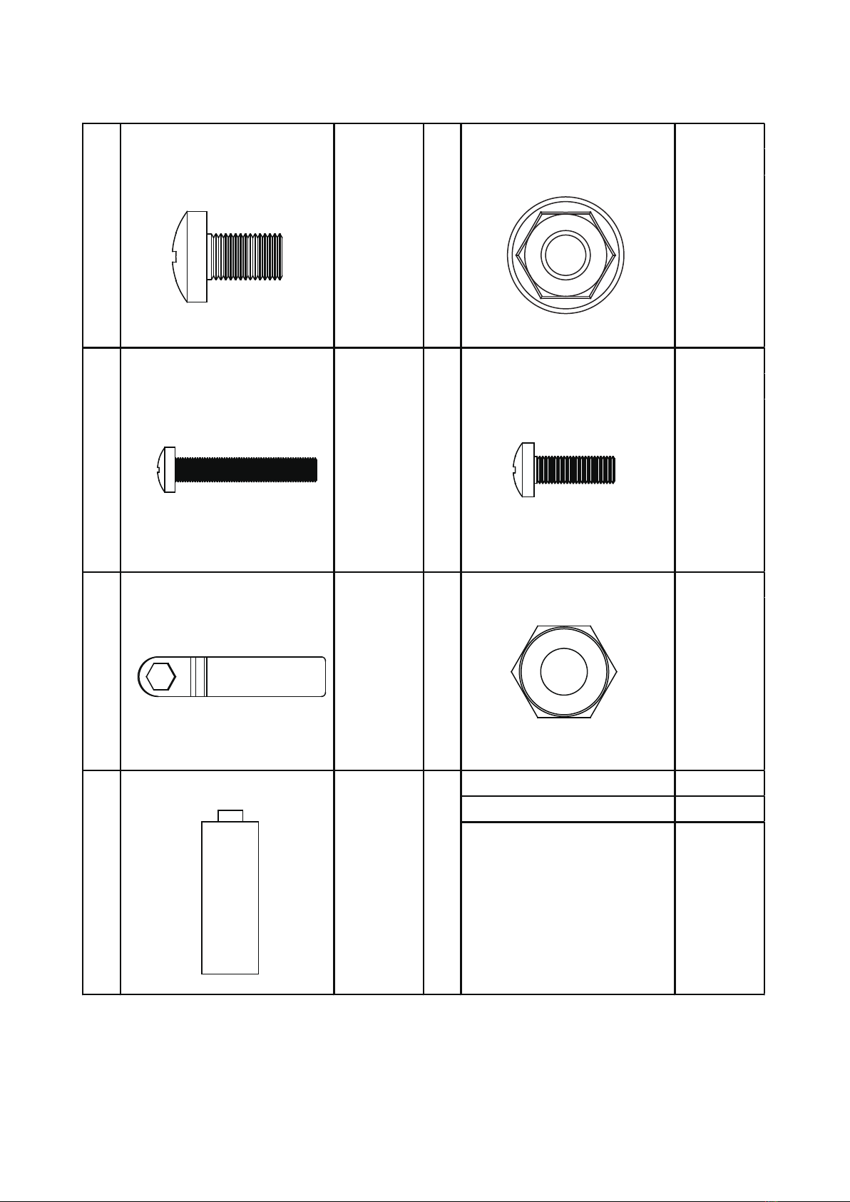
Spare parts
Bolt:M6×10mm 2PCS
Nut:M6 2PCS
2PCS6
30PCS 26PCS
3PCS4PCS
Nut
M6
Bolt
M4×12mm
Check nut
1PCS7 8
1 2
43
5 2PCS
Bolt
M6×10mm
Bolt
M5×30mm
Wrench
Battery
7
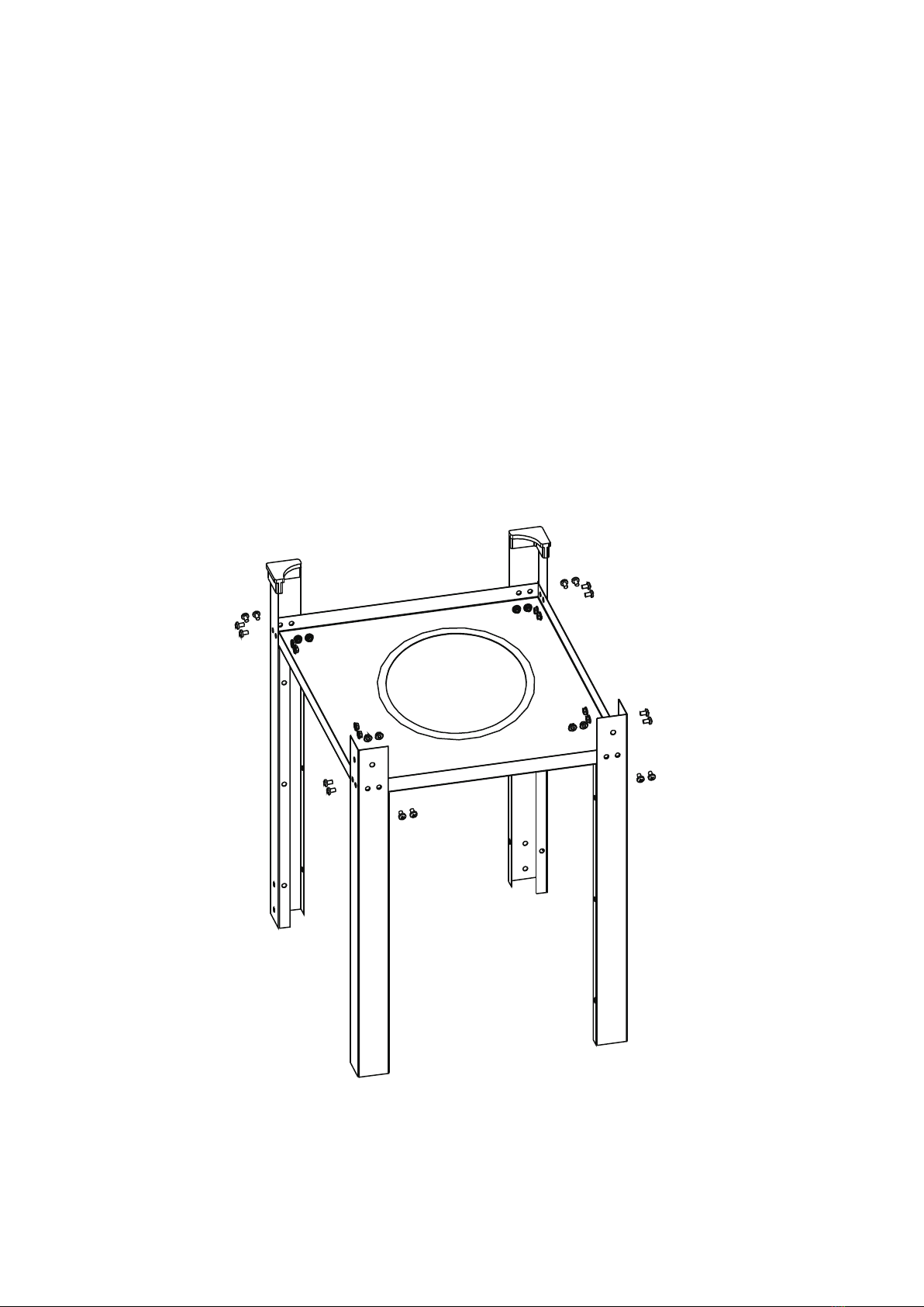
Use screw M6*10×16 pcs and nut M6×16pcs to fix the 4pcs Leg to the Cart bottom plate
as shown. (Note: 2pcs leg with plug please fix on the Cart bottom plate left, 2pcs leg
without plug please fix on the Cart bottom plate right.)
STEP1
ASSEMBLY INSTRUCTIONS
Before beginning assembly of product, make sure all parts are present. Compare parts
with package contents list and hardware contents list. If any part is missing or
damaged, do not attempt to assemble the product.
Assembly tip! (Please lightly tighten the screws during assembly of the cart.
When the cart is completed THEN TIGHTEN ALL THE screws. This will make it
easier to make all the holes align properly)

8
Assemble the wheel and wheel axle with 2 pcs check nut as shown.
STEP2
STEP3
M6*10×6 pcs and nut M6×6pcs to Assemble the wheel and wheel axle as shown.

9
M6*10×4 pcs and nut M6×4pcs to Assemble the handle as shown.
STEP4
STEP5
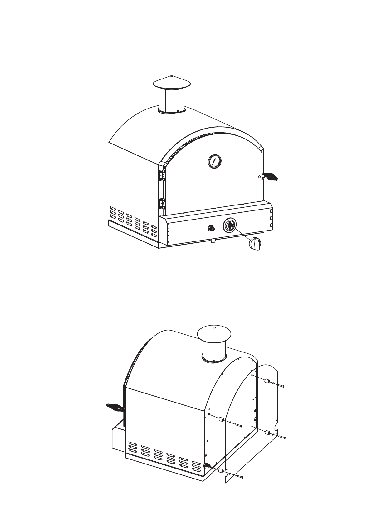
Use M4*12×3 pcs to Assemble the chimney as shown.
10
Insert the knob as shown.
STEP6
STEP7
Use screw M5*30×4 pcs and heat insulation washer to fix the back heat shield onto the
back panel of the oven as shown.
11
Use M6*10×4 pcs and nut M6×4pcs to Assemble the body and the cart as shown, use
bolt to tighten.
STEP8
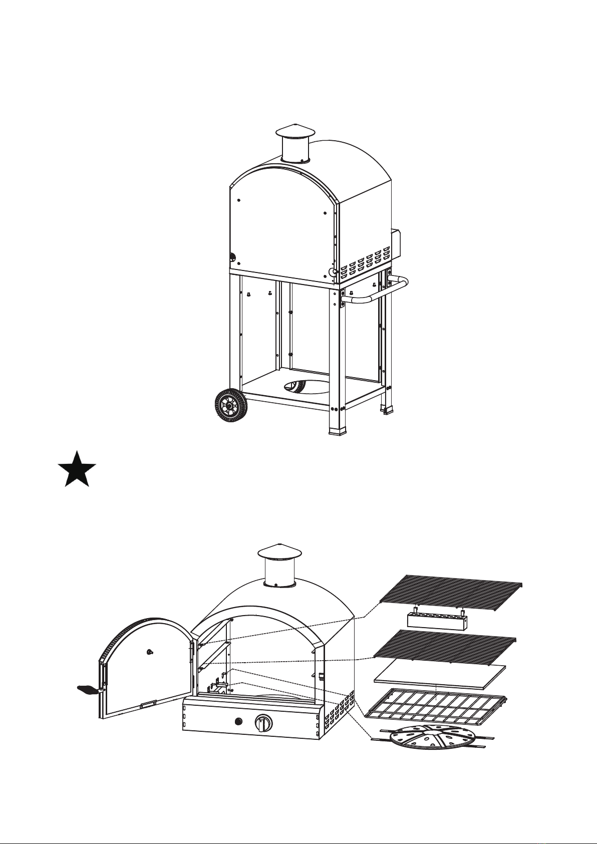
STEP9
Put the flame temper and smoker box assy (hang on the cooking grill ,exact position is
according to the food position ) into the oven as shown .
OPTIONAL ACCESSORIES

Fully-Assembled
12

13
GAS CONNECTIONS
GAS CYLINDER USE
In the case of a problem arising with the hose and regulator please contact your gas
oven supplier for a list of approved replacement parts . The hose and regulator
assembly parts must be an indication gas association approved part.
LEAK TESTING
This should be done the first time you connect up the barbecue, and again every time
you disconnect and reconnect any fitting. Inspect the hose before each use.
Turn the gas on at the cylinder , or make sure gas is available to the barbecue , but do
not turn the burners on. This fills the gas lines with gas .Now brush or pour some
soapy water onto all connections.If there is a leak ,bubbles should appear within about
20 seconds . If you find any leaks, tighten the connection. If the leak persist ,contact
your place of purchase.
As an alternative , you may use a gasleak derector, following the manufacturer’s
instructions, available at all major barbecue retailers .This provides an easier way to
check for leaks.
DO NOT USE NAKED FLAME FOR LOCATING GAS LEAKS .
IF A LEAK PERSISTS, CALL AN AUTHORISED PERSON.
WARNING
STORE CYLINDER IN A WELL VEBTILATED AREA
OUT OF REACH OF CHILDREN

14
LIGHTING PROCEDUE
OPERATING INSTRUCTIONS
1, Lighting the gas oven is easy ,but must be done with due care.
2, Make sure that gas is turned on at the cylinder ,or that gas is available to the gas
oven .
3, Make sure the LPG cylinder is filled.
4, Check that the end of the burner tube is properly located over the valve orifice.
5, Make sure all gas conne ctions are securely tightened.
6, Open the gas oven door.
7, Line the grease tray with “crumpled”aluminium foil.
MANUAL IGNITION
Place a lighted match or gas lighter (not provide).Keep your hand below the bottom of
the burner while doing this. Now turn the burner on. You should
See the burner alight. Repeat to light the other burners.
FLAME THROWER IGNITION
Note: Pulse ignitor requires one AA battery to operate.
1, Ensure the dooris open before lighting the burner.
2,Make sure the knob is in the “OFF” position.
3,Press and turn THE KNOB to the “HIGN” position and hpla down the KNOB. While
holding down the KNOB, press the “PULSE IGNITON” button to light the burner.
4,Continue pressing the “PULSE IGNITOR” button for the next 3 to 5 seconds .Once
the burneris lit, continue holding down the KNOB for another 5 to 8 seconds before
releasing the knob.
5,If the burner FAILS TO light, turn the KNOB to the “OFF”position and WHIT for
another 5 minutes before repeating the above steps.
CONTROLLING THE FLAMES
The knobs have three basic positions. You can achieve any flame height between low
and high rotating the knob between positions.

15
Note: “Blowback” is a situation where the flame burns inside the burner , towards the
front, recognised by a sharp roaring sound coming from the burner .It is not dangerous
unless allowed persist. If this occurs, simply turn the burner off, wait a fem seconds,
and then relight.
IMPAIRED VENTILATION OF HOT AIR FROM GRILL - In order for the burners to
function properly, hot air created by the burners must have a way to escape. The
burners may become deprived of oxygen, causing them to backfire, especially if the
burner output is set at HIGH. If this occurs repeatedly, the burners may crack. This is
the reason your grill was designed with ventilation louvers. These design features give
the hot air an escape route. Accordingly, never operate your grill with very little or no
open space at the cooking surface (the cooking gridsprovide sufficient space). Also,
never cover the ventilation louvers with foil or other materials that prevent air flow.
Specifically, do not cover the entire surface with foil, a large pan, etc
16
GENERAL MAINTENANCE
Care & Maintenance
- Keep outdoor cooking gas appliance area clear and free from combustible materials,
gasoline and other flammable vapors and liquids.
- Do not obstruct the flow of combustion and ventilation air.
- Keep the ventilation openings of the cylinder enclosure free and clear from debris.
- Visually check the burners.
GENERAL CLEANING
IMPORTANT: Before cleaning, make sure all controls are off and the grill is cool.
Always follow label instructions on cleaning products.
For routine cleaning, wash with soap and water using a soft cloth or sponge. Rinse
with clean water and dry at once with a soft, lint-free cloth to avoid spots and
streaks.To avoid scratching the surface, do not use steel wool to clean the grill.
Use a grill cover to protect finish from weather.
COOKING GRATES
The cooking grates can be cleaned immediately after cooking is completed and after
turning off the grill. Wear a barbecue mitt and scrub the cooking grates with a damp
cloth. If the grill is allowed to cool down, cleaning the grates will be easier if removed
from the grill and cleaned with a mild detergent.
This manual suits for next models
2
Table of contents
Popular Oven manuals by other brands


Siemens
Siemens CM656GB 1B instruction manual

Oursson
Oursson MO2305 instruction manual

Westinghouse
Westinghouse WST3028 user manual

Tricity Bendix
Tricity Bendix BS 690 GR Operating & installation instructions

Hotpoint Ariston
Hotpoint Ariston 7OFHR 640 RU/HA S operating instructions

Electrolux
Electrolux E40040-6 user manual


