ToolPRO POWER CUT 25K User manual


1 2
WARNING:
Read carefully and understand all ASSEMBLY AND OPERATION INSTRUCTIONS before
operating. Failure to follow the safety rules and other basic safety precautions may result in
serious personal injury.
GENERAL SAFETY RULES
WARNING: Read and understand all instructions. Failure to follow all instructions listed
below may result in serious injury.
CAUTION: Do not allow persons to operate or assemble this POWER CUT 25K
machine until they have read this manual and have developed a thorough understanding
of how the POWER CUT 25K works.
WARNING: The warnings, cautions, and instructions discussed in this instruction
manual cannot cover all possible conditions or situations that could occur. It must be
understood by the operator that common sense and caution are factors which cannot be
built into this product, but must be supplied by the operator.
IMPORTANT SAFETY CONSIDERATIONS
1.1 Your Cutting Environment
- Keep the environment you will be cutting in free from flammable materials.
- Always keep a fire extinguisher accessible to your cutting environment.
- Always have a qualified person install and operate this equipment.
- Make sure the area is clean, dry and ventilated. Do not operate the cutter in humid, wet or
poorly ventilated areas.
- Always have your cutter maintained by a qualified technician in accordance with local,
state and national codes.
- Always be aware of your work environment. Be sure to keep other people, especially
children, away from you while welding.
- Keep harmful arc rays shielded from the view of others.
- Mount the cutter on a secure bench or cart that will keep the cutter secure and prevent it
from tipping over or falling.
1.2 Your Cutter Condition
- Check ground cable, power cord and cutting cable to be sure the insulation is not damaged.
Always replace or repair damaged components before using the cutter.
- Check all components to ensure they are clean and in good operating condition before use.
1.3 Use of Your Cutter
Do not operate the cutting if the output cable, electrode, torch, wire is wet. Do not immerse
them in water. These components and the Cutter must be completely dry before attempting
to use them.
WARRANTY
This product is guaranteed against defects for lifetime of the product. This warranty is
provided by Super Cheap Auto Pty Ltd ACN 085 395 124 (Supercheap Auto) of 751
Gympie Rd Lawnton QLD 4501 Ph (07) 3482 7500. Supercheap Auto will offer a repair,
replacement product or store credit if the product is assessed as being defective during
the warranty period.
To claim under this warranty, take this product to the Front Service Desk of your nearest
Supercheap Auto store. For store locations, visit www.supercheapauto.com.au (AUS)
or www.supercheapauto.co.nz (NZ). You will need your receipt or proof of purchase.
Additional information may be requested of you to process your claim. Should you not
be able to provide proof of purchase with a receipt or a bank statement, identification
showing your name, address and signature may be required to process your claim.
This product may need to be sent to the manufacturer to assess the defect before
determining any claim. Faults or defects caused by product modification, misuse and
abuse, normal wear and tear or failure to follow user instructions are not covered under
this warranty.
Our goods come with guarantees that cannot be excluded under the Australian Consumer
Law. You are entitled to a replacement or refund for a major failure and for compensation
for any other reasonably foreseeable loss or damage. You are also entitled to have the
goods repaired or replaced if the goods fail to be of acceptable quality and the failure
does not amount to a major failure.
Any expenses incurred relating to the return of this product to store will normally have
to be paid by you. For more information contact your nearest Supercheap Auto store.
The benefits to the consumer given by this warranty are in addition to other rights and
remedies of the Australian Consumer Law in relation to the goods and services to which
this warranty relates.

3 4
- Follow the instructions in this manual.
- Keep Cutter in the off position when not in use.
- Connect ground lead as close to the area being cut as possible to ensure a good ground.
- Do not allow any body part to come in contact with the cutting wire if you are in contact with
the material being cut, ground or electrode from another Cutter.
- Do not cut if you are in an awkward position. Always have a secure stance while cutting to
prevent accidents. Wear a safety harness if working above ground.
- Do not drape cables over or around your body.
- Wear a full coverage helmet with appropriate shade and safety glasses while cutting.
- Wear proper gloves and protective clothing to prevent your skin from being exposed to hot
metals, UV and IR rays.
- Do not overuse or overheat your Cutter. Allow proper cooling time between duty cycles.
- Keep hands and fingers away from moving parts and stay away from the drive rolls.
- Do not point torch at any body part of yourself or anyone else.
- Always use this Cutter in the rated duty cycle to prevent excessive heat and failure.
1.4 Specific Areas of Danger, Caution or Warning
Electrical Shock
Electric arc Cutters can produce a shock that can cause injury or death.
Touching electrically live parts can cause fatal shocks and severe burns. While
cutting, all metal components connected to the wire are electrically hot. Poor ground
connections are a hazard, so secure the ground lead before cutting.
- Wear dry protective apparel: coat, shirt, gloves and insulated footwear.
- Insulate yourself from the work piece. Avoid contacting the work piece or ground.
- Do not attempt to repair or maintain the Cutter while the power is on.
- Inspect all cables and cords for any exposed wire and replace immediately if found.
- Use only recommended replacement cables and cords.
- Always attach ground clamp to the work piece or work table as close to the cut area as
possible.
- Do not touch the cutting wire and the ground or grounded work piece at the same time.
- Do not use a Cutter to thaw frozen pipes.
Fumes and Gases
- Fumes emitted from the cutting process displace clean air and can result in injury or death.
- Do not breathe in fumes emitted by the cutting process. Make sure your breathing air is clean
and safe.
- Work only in a well-ventilated area or use a ventilation device to remove cutting fumes from
the environment where you will be working.
- Do not cut on coated materials (galvanized, cadmium plated or containing zinc, mercury
or barium). They will emit harmful fumes that are dangerous to breathe. If necessary use a
ventilator, respirator with air supply or remove the coating from the material in the weld area.
- The fumes emitted from some metals when heated are extremely toxic. Refer to the material
safety data sheet for the manufacturer’s instructions.
- Do not cut near materials that will emit toxic fumes when heated. Vapors from cleaners,
sprays and degreasers can be highly toxic when heated.
UV and IR Arc Rays
The cutting arc produces ultraviolet (UV) and infrared (IR) rays that can cause injury
to your eyes and skin. Do not look at the cutting arc without proper eye protection.
- Always use a helmet that covers your full face from the neck to top of head and
to the back of each ear.
- Use a lens that meets proper standards and safety glasses.
- Cover all bare skin areas exposed to the arc with protective clothing and shoes. Flame-
retardant cloth or leather shirts, coats, pants or coveralls are available for protection.
- Use screens or other barriers to protect other people from the arc rays emitted from your
cutting.
- Warn people in your cutting area when you are going to strike an arc so they can protect
themselves.
Fire Hazards
Do not cut on containers or pipes that contain or have had flammable, gaseous
or liquid combustibles in them. Cutting creates sparks and heat that can ignite
flammable and explosive materials.
- Do not operate any electric arc Cutter in areas where flammable or explosive materials are
present.
- Remove all flammable materials within 35 feet of the cutting arc. If removal is not possible,
tightly cover them with fireproof covers.
- Take precautions to ensure that flying sparks do not cause fires or explosions in hidden
areas, cracks or areas you cannot see.
- Keep a fire extinguisher close in the case of fire.
- Wear garments that are oil-free with no pockets or cuffs that will collect sparks.
- Do not have on your person any items that are combustible, such as lighters or matches.
- Keep work lead connected as close to the cutting area as possible to prevent any unknown,
unintended paths of electrical current from causing electrical shock and fire hazards.
- To prevent any unintended arcs, cut wire back to ¼” stick out after cutting.
Hot Materials
Cut materials are hot and can cause severe burns if handled improperly.
- Do not touch cut materials with bare hands.
- Do not touch gun nozzle after cutting until it has had time to cool down.
Sparks/Flying Debris
Cutting creates hot sparks that can cause injury. Chipping slag off cutting creates
flying debris.
- Wear protective apparel at all times: safety glasses or shield, Cutter’s hat and ear
plugs to keep sparks out of ears and hair.

5 6
Electromagnetic Field
- Electromagnetic fields can interfere with various electrical and electronic
devices such as pacemakers.
- Consult your doctor before using any electric arc Cutter or cutting device
- Keep people with pacemakers away from your cutting area when cutting.
- Do not wrap cable around your body while cutting.
- Wrap torch and ground cable together whenever possible.
- Keep torch and ground cables on the same side of your body.
Shielding Gas Cylinders Can Explode
High pressure cylinders can explode if damaged, so treat them carefully.
- Never expose cylinders to high heat, sparks, open flames, mechanical shocks or
arcs.
- Do not touch cylinder with cutting torch.
- Do not cut on the cylinder
- Always secure cylinder upright to a cart or stationary object.
- Keep cylinders away from cutting or electrical circuits.
- Use the proper regulators, gas hose and fittings for the specific application.
- Do not look into the valve when opening it.
- Use protective cylinder cap whenever possible
1.5 Proper Care, Maintenance and Repair
-Always have power disconnected when working on internal components.
- Do not touch or handle PC board without being properly grounded with a wrist strap. Put PC
board in static proof bag to move or ship.
-Do not put hands or fingers near moving parts such as drive rolls of fan
USE AND CARE
• Do not modify the POWER CUT 25K in any way. Unauthorized modification may impair
the function and/or safety and could affect the life of the equipment. There are specific
applications for which the POWER CUT 25K was designed.
• Always check of damaged or worn out parts before using the POWER CUT 25K. Broken
parts will affect the POWER CUT 25K operation. Replace or repair damaged or worn parts
immediately.
• Store idle POWER CUT 25K. When POWER CUT 25K is not in use, store it in a secure place
out of the reach of children. Inspect it for good working condition prior to storage and before
re-use.
PRODUCT INTRODUCTION
POWER CUT 25K is regarded as metal cutter equipment with high efficiency. Its working
principle is to use the compressed air as the ionization medium, and then form the high density
plasma arc heat source by the torch nozzle’s compress effect, which melt the metal as a result.
The melted metal will be blown off by the high speed gas flow at the same time to form into
narrow cutting slot, thus the metal can be melted and cut very rapidly.
This cutting equipment possesses good features like easy operation, energy saving, high
speed cutting, narrow and glabrous cutting slot, less deformation of work pieces, reliable and
safe apply, low investment etc. It is suitable for almost all metal plate and pipe materials,
including mild steel, stainless steel, aluminum, copper, titanium, nickel allo y, cast iron etc. It is
widely used in every work of life such as ship building, motor manufacturing, metal structure,
boiler, pressure vessel and pipe making, medical appliance and machinery making etc.
The feature of POWER CUT 25K:
• Small and light, the weight of POWER CUT 25k is only 9.6Kg.
• Advanced IGBT inverter technology attributes to stable capability, high efficiency and energy
saving
• Work can be reliable at ±20% of fluctuation for input voltage.
• Visible gas adjustment and easy operation, specially suitable for decoration.
• The cutting thickness capacity of machine POWER CUT 25K will reach 8mm.
• Cutting slot both narrow and glabrous, no damage to the work pieces. Commendatory
thickness attributes to high quality.
• Complete protective function includes the protections of Built-in over current, High frequency
contact arc function.
SAFETY OPERATION
Operator’s Self Protection
• Please always follow the rules that conform to safety and hygiene. Wear protective garments
to avoid injuries to eyes and skins
• No touch to the working piece while operation in case of the electric leaking accident occurred
• No touch to the two output polarity (The polarity of the torch and the polarity of the work
piece) at the same time without any insulation protection.
• No permission to cut the vessel with inflammable and explosive materials or the sealed
pressure vessel.
• Avoid operation under water or high humidity places.
• Shut off the power supply before changing the consumable parts.
• Prohibit aiming the torch at any part of the body.
• Prohibit touching the contact part of the torch after the cutter is on.
Attention
• POWER CUT 25K cutter is electronic products whose spare parts are very tender, do not
change or adjust with a rush otherwise the switch will be damaged.
• Check the connection to see if it is well connected, whether the earth (ground) connection
is reliable, etc.

7 8
• Fumes and gases produced when cutting are hazardous to health. Make sure to work in
places where there are exhaust or ventilation facilities to keep fumes or emissions away
from the breathing zone.
• Insulate the working area since spatter will be occurred.
• No access to switching or modulating by others while the cutter is working
• Cutters have strong electromagnetism and frequency interference, so keep away people
with heart pace or the articles which can be interfered by electromagnetism and frequency.
• No squeeze or punch to the cutting cable.
• Never clean the slag in the torch head by violent knocking.
• The puckering angle of the torch cable can not be too small, otherwise the inside cable of
gas pipe will be damaged which can result into accident.
• Never allow anybody else other than the operator himself to access the job site.
• No touching on the output connection or any other electrification parts while welding.
Safety Measures to Be Taken To Assure the Correct Installation and Position
• Precaution must be taken to keep the operator and the machine from the foreign materials
falling from up above
• The dust, acid and erosible dirt in the air at the job site can no exceed the amount required
by the norm (excluding the emission from the cutter).
• The cutting machine must be installed in the place where it can no be exposed to sun and
rain. Also it must be stored in less humid place with the temperature range at -10˚C~+40˚C.
• There should be 50cm space left for the cutting machine to have good ventilation.
• Make sure that there is no metal-like foreign body to enter the cutting machine.
• No violent vibration in the cutter’s surrounding area.
• Make sure the machine is installed in where it won’t interfere the surrounding electromagnetism
equipment during the operation.
• Take measures to prevent wind while operating in the strong wind since the cutter is gas
shielded.
Safety Check
Each item listed below must be carefully checked before operation:
• Make sure that the cutting machine has reliable earth connection.
• Make sure that there is always sound output and input wire connection instead of exposing
outside.
Regular check needs to be conducted by the qualified personnel after the cutter has been
installed over a period of six months, which involves as follows:
• Routine cleaning is required to make sure there is no abnormal condition happening in the
tightened places such as the loose and slipped magnetic core, regulating screw, connecting
wire happening in the cutting machine.
• The external parts installed on the cutter’s panel must guarantee that the Cutter works
properly.
• Fresh the cable of the cutter if it is worn out.
• Any damage to the input cable if occurred should be dealt safely.
• Make sure whether there is enough power supply to make the cutting machine work
properly, and the power supply connected into the cutter should be equipped with safety
protection device.
TECHNICAL SPECIFICATIONS
Environment for the Product
• The surrounding temperature range:
When cutting: -10˚C~+40˚C
During transport or in storage: -25˚C~+55˚C
• Relative humidity:
When at 40°C: ≤50%
When at 20°C: ≤90%
• The dust, acid and erosible materials in the air can not exceed the amount required by the
norm (apart from the emissions from the cutter ). No violent vibration at the job site.
• Keep out from raining when it is used outdoor.
Requirement for Main Supply
• The voltage oscillogram should display actual sine wave.
• The oscillation of the supplied voltage should not exceed ±20% of the rated value.
• Frequency fluctuation should be less than ± 2%.
Theory of Cutting Machine (see the principle chart)
The principle chart
POWER CUT 25K is high speed cutting equipment with advanced technology which is using
high density plasma arc as source of the heat. The plasma arc would be acquired by the
compressed air as ionization medium and the compression of the torch’s nozzle.
The main electric theory of POWER CUT 25K 240V single-phase industrial AC power is
required, and transfer to DC after rectified by Single phase rectification bridge and transformed
by the middle frequency transformer, and then rectified to the DC by the fast recovery diode,
While starting cutting, the nozzle and electrode are separated quickly by the air pressure, the
voltage between them make the air are ionization and arc which is moved between work piece
and electrode pilots .
Cutter’s Structure
POWER CUT 25K applies portable box structure: power indicator light, protect indictor
light, the cutting current adjust knob, are installed on the first half of the front board; and
the current output ‘+’ electrode quick connector, ‘-’ electrode quick connector, cutting torch
control(two pins socket), switch socket are installed on the next half; the power inlet, Argon
input connector and power switch, are installed on the back board; the control transformer,
control press circuitry board can be seen on the first installation board after shelling the out

910
case; the rectification bridge , electrolytic capacitor etc. are installed on the bottom, the
medium frequency transformer, fast recovery rectifiers, heat sink etc. are installed in the
centre of the box.
Cutter Type Coding
• Combination of the English letter and the Arabic numerals.
• Implication of Coding:
Main Technical Data
Items Unit POWER CUT 25K
Rated input voltage V 240
Power supply frequency Hz 50/60
Phase PH. 1
Rated input capacitance KVA 3.8
Rated input current A 15.8
Output non-load voltage V 306
Rated operation voltage V 90
Output Current A 15-25
Gas flow L/min 300
Air pressure MPa 0.30~0.6
Lag gas time s 5~10
Max cutting thickness mm 8
Rated duty cycle % 40
Cooling type Fan-cooled
Arc start type High-frequency transfer arc
Insulation grade grade H
Case Protection Class IP IP21S
Weight kg 9.6
Dimension (L*W*H) mm 432*173*331
Applying Norm of Cutter
POWER CUT 25K conforms with the AS 60974-1standard to perform.
INSTALLATION & MAINTENANCE OF THE TORCH & REPLACEMENT OF THE
SPARE PARTS
Notice: please make sure the power supply switch is off before loading/unloading the cutting
torch and replacing the spare parts.
• The installation of the torch’s spare parts should follow the order according to the pictures
listed blow. Please notice during the installation: the distributor should not be installed in
reverse, and the protection cover should be screwed tightly, but please be alert that over
pressure would smash the distributor.
• While the nozzle’s hub hole is burnt to a degree that it will affect the cutting slot, it should
be replaced in time
• The electrode should be replaced in time when it worn down or be shortened to about 2mm,
otherwise the torch will be broken. (See the following pictures.)
Cutting Torch Assemble Sketch
• If there are any spare part such as the torch’s protection cover or the distributor are
broken, they should be replaced in time.
• The torch’s cable, working gas pipe, protection cover or the wire are broken, then they
should be replace in time
Remark of Illustration
Ground
Descending
Plasma Cutting
Power Source & AC 1 Phase
1 Phases Arc Welding transformer -- Rectifier
DC
Type

11 12
X: Duty Cycle
I1: Rated Input Current
I2: Rated Cutting Current
P1: Rated Input Power
U0: Rated Open Circuit Voltage
U1: Rated Input Voltage
U2: Rated Load Voltage
~50Hz: AC, Rated Frequency 50Hz
...V: Unit of Voltage
...A: Unit of Current
...KVA: Unit of Power
...%: Unit of Duty Cycle
...A/...V: Cutting Current and Relevent Load Voltage
...MPa: Unit of Pressure
….bar: Unit of Pressure
AS60974-1: Safety standard for the welding equipment
IP21S: Grade for the case protection. IP is the code of International Protection. 2 mean
preventing user’s finger from the dangerous parts; preventing the solid material with the
diameter no less than 12.5mm into the box. 1 means preventing water dropping vertically
which is harmless. S means water proof test is conducting while the movable part is
standstill.
H: H insulation grade
INSTALLATION (SEE FOLLOWING PICTURES)
Cutter’s Placement
• The dust, acid and erosible dirt in the air at the job site can not exceed the amount
required by the norm.
• The Cutter must be installed in the place where it can not be exposed to sun and rain. Also
it must be stored in less humid place with the temperature range at -10~+40°C.
• There should be 50cm space about for the machine to have good ventilation.
• Apparatus to exclude wind and smoke should be equipped if the inside aeration is not
sound.
APPEARANCE AND CONNECTION
Connection Sketch
Front Panel Back Panel
1. Connector for
Torch(“-”)
2. Air Pressure Meter 3. Power Indicator 4. Handle
5. Protection
Indicator
6. Current Adjusted
Knob
7. Socket(3-pins) 8. Connector for Work
piece (“+”)
9. Fan Cover 10. Gas Inlet 11. Gas lock 12. Power On/Off
Switch
13. Power cable
Entrance

Connection between Cutter and Power Supply
• Connect the ‘Power Supply Input Cable’ on the back board of the cutter to the single-
phase power supply;
• Connect the ‘Safe Earth Connection Bolt’ with the power supply earth cable reliably with the
lead whose section area is not less than the cutter’s input lead’s
• Power Supply Configure of one Cutter:
ITEMS POWER CUT 25K
Air switch (A) ≥30
Fuse (A) 35
knife switch (A) ≥30
Supply cable (mm2) ≥4
Notice: The melting current of the fuse is two times of its rated current
Connection between Cutter and Compressed Air
• Connect the output of the decompressed air to the “gas input ” on the back panel by gas
pipe with thread.
OPERATION (SEE SKETCH OF CUTTER’S BOARD)
Operation
• Check the cutter which has finished connection according to the items of the ‘Operation’
to be sure that the connection is correct and reliable; check according to the items of the
‘Safety Operation’ to be sure that it complies with the safety operation requirements;
• When the supply power is on, (Voltage Displayer) shows the input power supply voltage;
Switch on the power supply switch of the cutter to observe if the operation state is normal.
If it is normal, the fan should start up; the (Power Supply Indication Light) should be on. If
there is no compressed air or the air pressure is not enough, the (Pressure Lack Indication
Light) will sign;
• Switch the Torch cooling switch to the ‘Gas Cooling’, adjust air decompression valve till the
air pressure is up to the cutting craft’s requirement. (The lowest pressure should be no less
than 0.33MPa), the (Pressure Lack Indication Light) won’t sign at that condition;
• Adjust the (Gas Check) to the gas check position to observe if the compressed air is
smooth.
• Turn on the torch switch; the cutting operation then begins after the cutting plasma pilot is
made.
Manual cutting
Manual Contact Cutting
• Put the torch’s nozzle at the start of the work piece (with slight touch or lift). Turn on the
torch switch to ignite the plasma pilot. After the work piece is cut thoroughly, then move the
torch along the cutting direction uniformly. The cutting speed should be aimed to cutting
thoroughly. If the speed is too quick, the work piece won’t be cut very thoroughly, or if
too slow, the cut quality would be affected even result into broken arc. (See the following
picture)
• Turn off the torch after the cutting, then the plasma pilot will extinguish and then withdraw
the torch. The cutting process is over then.
Notice while cutting
• If unnecessary, please do not ignite the leading pilot in the air, or it will reduce life-span of
the torch’s electrode and puzzle.
• It will be better to start cutting at the edge of the work piece, unless you must do
perforation operation on the work piece.
• Be sure that the splash is spilt from the bottom of the work piece. If it is spilt from the top
of the work piece, then you must move the torch not too quickly, or the thickness you
chose could not cut through the work piece.
• Keep certain space between the nozzle and the work space. If press the torch onto the
work piece heavily, it will make the nozzle stick onto the work piece, thus it can not move
smoothly to cut.
• Templet or accessorial equipment is required to cut round work piece and edge
inosculation work piece.
• It is easier to “pull” than “push” during the cutting process
• Keep the torch’s nozzle vertical against the work piece, and observe if the pilot is moving
along the cutting line.
• While cutting the thin work piece, the thin mode can get best cutting quality with low
wastage and longer life span of electrode and nozzle.
• Do not repeat to press the torch switch rapidly, otherwise the pilot system and relative
work piece will be destroyed.
• The Non-HF Arc-pilot Series cutter’s working range is 0.4~0.45MPa. HF Arc-pilot Series
cutter’s working range is 0.50~0.55MPa.
Safety Requirement
• Never allow the electrophorus torch to aim at any part of the body.
• Make sure to wear protection glasses and protection glove while operating.
• Make sure to work in places where there are exhaust or ventilation facilities to keep fumes
or emissions away from the breathing zone.
• No touching to the work piece while cutting in case of the creep age leading into
accident.
• Never allow to cut the vessel that is or was with flammable or explosive stuff
• Torch cable is not allowed to work under water or in the moist environment
• The puckering angle of the torch cable can not be too small, otherwise the inside cable of
gas pipe will be damaged which can result into accident.
• Never allow anybody else other than the operator himself to access the working area.
• Make sure to turn off the power supply when dismantling or moving the machine
• Make sure to turn off the power supply when dismantling or installing any spare parts
(such as torch, electrode, nozzle, earth clamp or other spare parts)
• Make sure to turn off the power supply when dismantling or moving the machine.
• Never allow people with heart pace close to the working site without the permission of the
doctor. The magnetic field produced by the cutters during operation will cause negative
affect to the heart pace.
• The cutting cable can not be pressed or shocked by any appliance.
• Never clean the slag in the torch head by violent knocking.
13 14

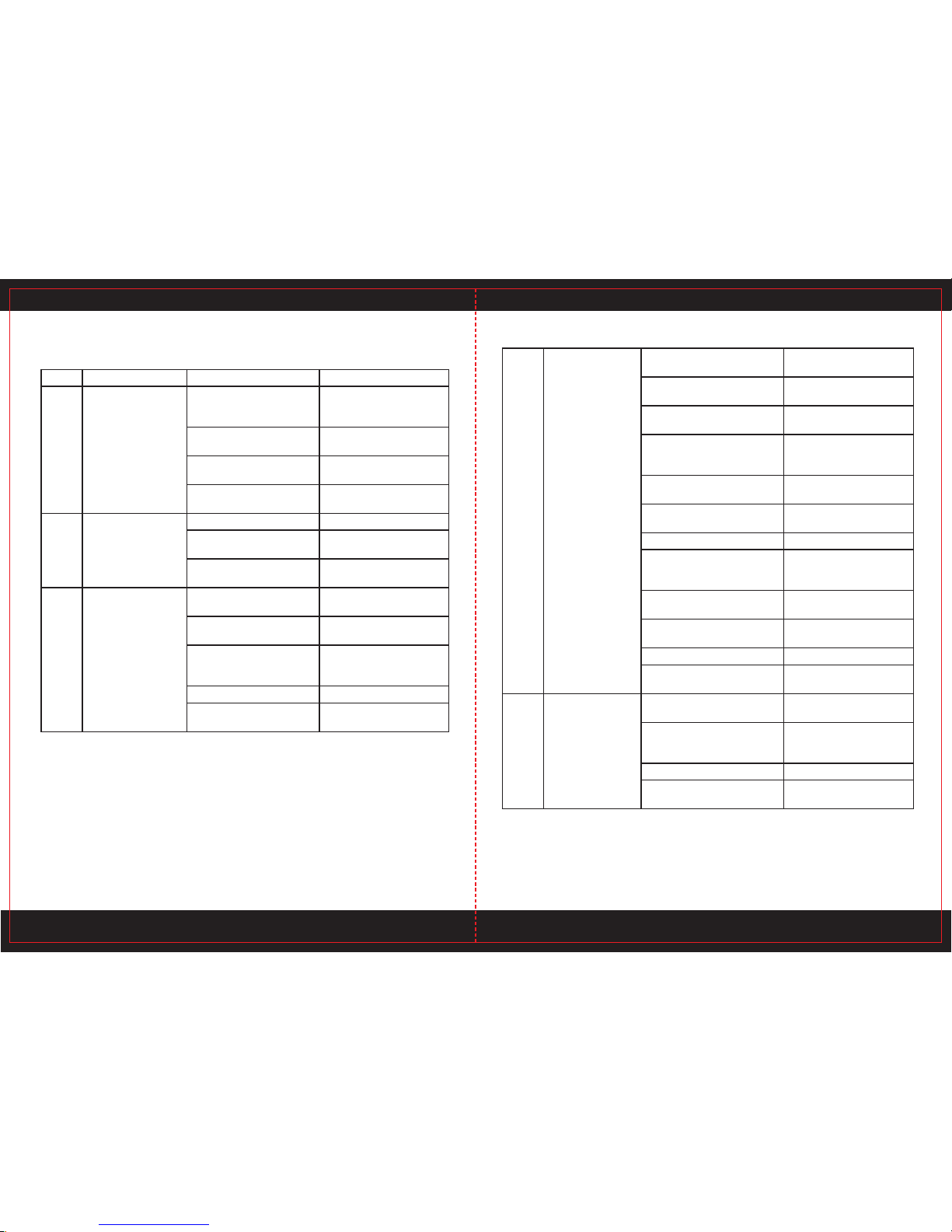
TROUBLE SHOOTING
Breakdown and Solutions
No. Breakdown Analysis Solutions
1 Indication Light is off
after turning on the
power supply.
The light is broken Replace
Fuse is ruined. Replace
No 240V Input Voltage Get through 240V
Input cable
Power supply switch is
broken
Replace
Controlling board or cutter is
ruined
Examine and repair
2 Fan doesn’t work after
turning on the power
supply
Fan is ruined Replace
Fan’s down-lead is broken Examine and repair
Fan’s leaf is blocked Clean the block
Transformer is ruined Replace
3 Pressure lack Indication
Light is on
No input compressed air Examine and repair
Air pressure valve is adjusted
to 0 or broken
Adjust or Replace
Gas circuit is blocked Clean the block
Gas valve is ruined Replace
4 No gas check function Gas valve is ruined Replace
Gas circuit is blocked Clean the block
Gas check switch is ruined Replace
Down-lead is broken Examine and repair
5 Can’t cut or no high
frequency output
Discharge gap is too big Adjust to suitable gap
High pressure mica capaci-
tance ruined
Replace
Pilot transformer is ruined Replace
Main controlling board is
ruined
Examine and repair
Down-lead is broken Examine and repair
6 Can’t cut or no current
output
Torch is broken Examine and repair
Commutate module is
broken
Replace
AC contacting equipment is
broken
Replace
Cutting thickness mode
switch is broken
Replace
Main controlling board is
ruined
Examine and repair
Down-lead is broken Examine and repair
7 No response after turn-
ing on the torch switch
Switch and down-lead are
broken
Examine and repair or
Replace
Switch board is broken Examine and repair or
Replace
Main controlling board is
ruined
Examine and repair or
Replace
Transformer is ruined Replace
Down-lead is broken Examine and repair
8 No response after
turning on power supply
Lack of phase Examine and repair
Power supply switch is
broken
Replace
Fuse is ruined Replace
Transformer is broken Replace
Main controlling board is
ruined
Examine and repair or
replace
15 16
The Techniques Breakdown and Analysis
No. Breakdown Analysis Solutions
1 Work piece is not cut
thoroughly
The cutting current is too
low
Adjust ‘Cutting thickness
Mode Switch’ to ‘Thick
Mode’
The cutting speed is too
rapid
Slow down the cutting
speed
Torch electrode or nozzle is
burn out
Replace electrode or noz-
zle
Cut thickness exceeds the
limit of the cutter
Replace with high-power
cutter
2 Slag drop out from
the Cutting Mouth of
Work Piece
Cutting Speed is too slow Accelerate cutting speed
Cutting Electrode or Nozzle
is burnt
Replace electrode or noz-
zle
Cutting current is too high Adjust cutting thickness
mode to ‘thin’ mode
3 Pilot is not stable
during operation
Compressed gas is too low
or too high
Adjust pressure
Electrode of cutting torch
or nozzle is burnt
Replace electrode or
nozzle
Connection between
cutting cable and work
piece is poor
Connect firmly
Cutting speed is too slow Adjust speed
Input AC voltage is too low Adjust power supply or
voltage
4 Cutting thickness is
not up to the rated
standard
Slag drop out from
the Cutting Mouth
of Work Piece
Pilot is not stable
during operation
Input compressed air pres-
sure is too low or too high
Adjust air pressure
Input compressed air flow is
too low
Adjust air flow
Cutting speed is too quick Slow cutting speed
Material of work piece is not
symmetry with the thickness
standard
Adjust
Nozzle or electrode is burnt Replace nozzle or elec-
trode
Nozzle type is not right Replace with a suitable
nozzle
Cutting mouth is not vertical Adjust cutting mouth angle
Gas leak from the gas circuit,
making the true cutting flow is
not enough
Examine and repair the
gas circuit
Input power supply is a bit
low
Adjust the power supply
Input or output lead is too
thin or pressure is too big
Widen down-lead
Cutting speed is too slow Adjust speed
Input AC voltage is too low Adjust power supply or
voltage
5 Cut is a bit declin-
ing
Nozzle or electrode is burnt Replace nozzle or elec-
trode
The installation position of
nozzle and electrode is not at
the same axes
Install again correctively
Cutting speed is too high Adjust cutting speed
Nozzle axes is not plumb with
the plane
Adjust the torch angle
17 18
6 Cut is too wide,
processing quality
is poor
Cutting speed is too slow Accelerate cutting speed
Torch’s electrode or nozzle is
burnt down
Replace electrode or noz-
zle
Cutting speed is too high Adjust cutting thickness
mode to “thin” mode
Type of nozzle is not right Replace with a suitable
nozzle
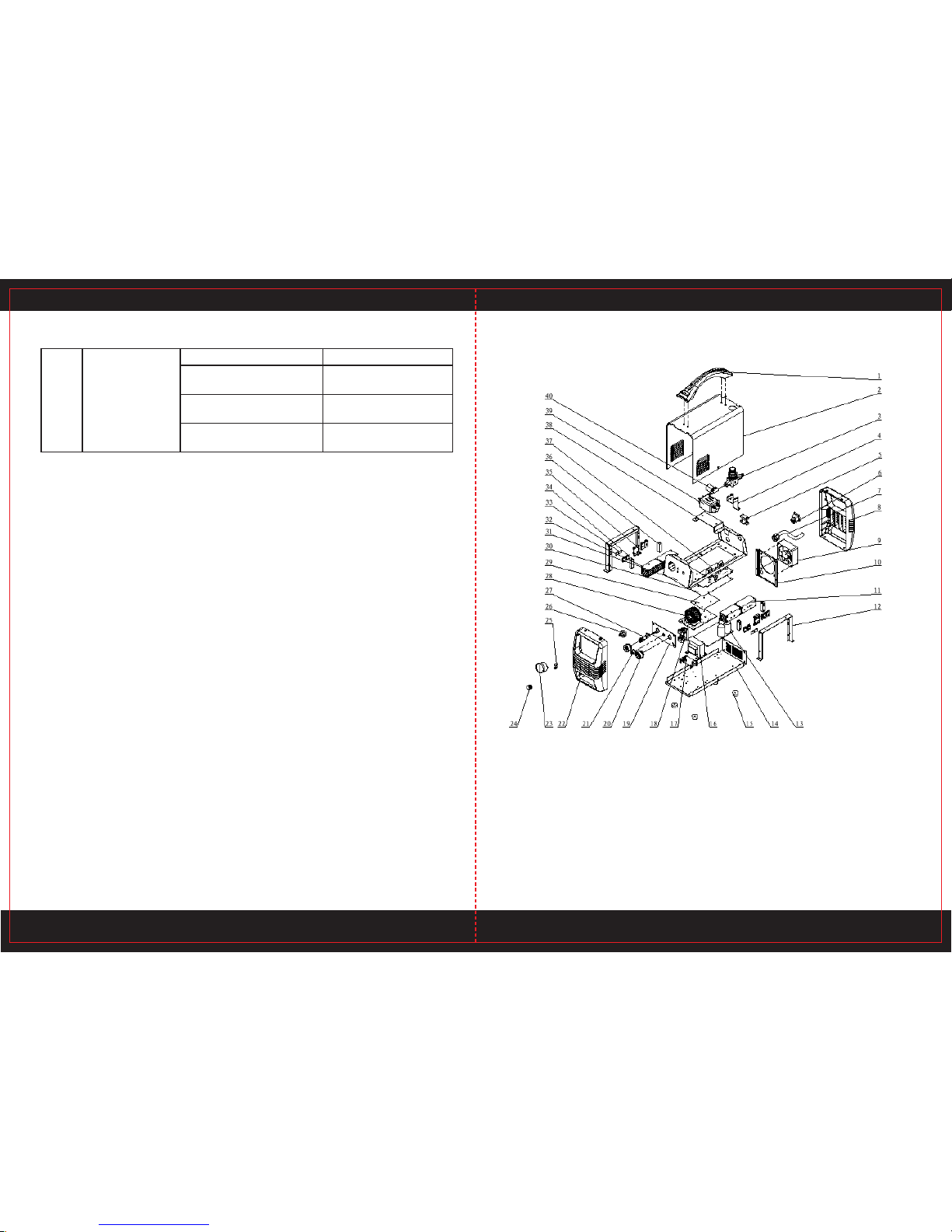
PARTS LIST
19 20
No Description pcs No Description pcs
1 Handle 1 21 Switch harness for gun 1
2 Enclose 1 22 Plastic frame 1
3 Gas valve connector 1 23 Gas regulator 1
4 Bracket for valve 1 24 Potentiometer knob 1
5 Cable holder 2 25 Indicator light 1
6 Rocker switch 1 26 Welding potentiometer 1
7 Input power line 1 27 Gas power connector 1
8 Plastic frame 1 28 Main transformer 1
9 Fan harness 1 29 Insulating plate for transformer
rectifier board
1
10 Fan cover 1 30 Insulating plate for main
control panel
1
11 Heat sink for IGBT 1 31 Assembling panel 1
12 Bracket for heat sink 2 32 Heat sink for fast recovery 1
13 Arc starting plate 1 33 Pressing plate 2
14 Bottom panel 1 34 Fast recovery diode 4
15 Feet 4 35 Heat sink junction plate 2
16 Output reactor 1 36 Support strip 4
17 Bracket for torch trigger # 1 37 Main control panel 1
18 Coupling transformer 1 38 Bracket for rectifier 1
19 Output panel 1 39 EMI 1
20 Europe type quick socket 1 40 Air valve 1
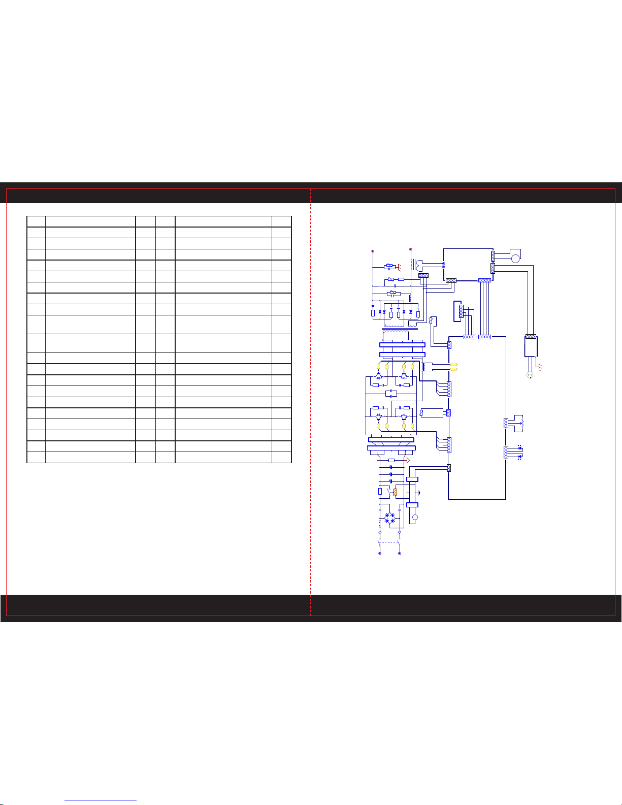
Circuit Chart
SW1
BD1
C4
C5
10
R2
J1
C1 C2 C3 R1
1
2
CN1
1
2
3
4
7
5
6
CN3
Q1
Q3
R1
C1
R3
C3
G1
E1
G3
E3
Q2
Q4
C2
C4
G2
E2
G4
E4
R5
R4
TR1
+V
INPUT
RV1
C6 OUTPUT
+
1
2
3
4
5
CN12
C43 C42
1
2
3
4
5
CN11
1
2
3
4
5
CN11*
1
2
CN2
JP1
P1
P2
C1
R1
C4
R4
12345 12345
G1
G3
E1
E3
G2
G4
E2
E4
CUR ADJ
1 2 3
F
FAN1
ZKB V1.0
CN7
+24
Digital Disp
3 41 2
GND
GND
+5V
Signal
2 1
CN10
T2
P3 P4
1
2
3
CN2
123
CN6
+
1
2
123
1 2 3
CN5
TIG 200 KGB
CN1
WS-200I DYB
Torch switch
1234
CN4
1234
CN4
D2
D1
D4
D3
C3
R3
C2
R2
L2
2
6
3
1
4
5
*
21:18:4
C5
L1
RV2 RV3
C7
R2
-
CS+
CS-
1234
CN8
3 41 2
CN13
Power
Error
RV5
1 2
CN9
1 2
CN12
RV4
QF
220V AC
1 2 3
CN2
21 22

COMPLETE SET SPECIFICATION
Complete Set Supply
• POWER CUT 25K 1
• Cutting Torch 1
• Earth Cable with Clamp 1
• Operator’s Manual 1
• Air Hose 1
Notice: a) No guarantee has been made yet to get the accessories repaired at any time
because of its breakable attribute.
b) The accessories for manual or automatic round cutting should be equipped
separately.
TRANSPORT & STORAGE
• This product is box structure, hold the handle or the bottom to move it. The machines
should be firmly fixed during the transportation.
• The machine should be free from rain and snow. Keep notice of Attention sign on the
packing box. The storage ware should keep dry and air circulation & free from corrosive
gas or dust. The tolerable temperature ranges from -25˚C to +55˚C, and the relative
humidity can not be more than 90%.
• After the package has been opened, it is suggested to repack the product as per
requirement for future storage and transport. (Cleaning job is required before storage and
enseal the plastic bag for storage in the box)
• Users should keep the packing materials with the machines to keep well storage during the
long transportation. If the machines need transfer during the transportation, then wooden
box is required. Sign such as ‘Lift’ and ‘Free of rain’ should be labeled on the box.
23 24
Table of contents
Popular Welding System manuals by other brands

Mweld
Mweld WAVE 200DIII owner's manual

Sealey
Sealey SUPERMIG180.V4 instructions

Magmaweld
Magmaweld RD 500 E user manual

Lincoln Electric
Lincoln Electric Power Wave AC/DC 1000 brochure

Lincoln Electric
Lincoln Electric BESTER 210MP Operator's manual

Lincoln Electric
Lincoln Electric spirit II 150 Technical manual


REHM
REHM TIGER DIGITAL 230 AC/DC ULTRA operating instructions

ESAB
ESAB EMP 215ic Service manual

EWM
EWM alpha Q 330 Progress puls MM TKM operating instructions

Helvi
Helvi GLOBUS 201 instruction manual

Chimera
Chimera ARC-110 operating manual

Campbell Hausfeld
Campbell Hausfeld WG2060 Operating instructions and parts manual