Toolshop 241-9825 User manual

1/2” 6.7 AMP HAMMER DRILL
241-9825
SAVE THIS MANUAL
You will need this manual for safety instructions, operating procedures and warranty.
Put it and the original sales receipt in a safe dry place for future reference.
Operator’s Manual
FRANÇAIS
IMPORTANT SAFETY INSTRUCTIONS
WARNING:When using electric tools, machines or equipment, basic safety pre-
cautions should always be followed to reduce the risk of fire, electric shock,
and personal injury.
READ ALL INSTRUCTIONS BEFORE USING THIS TOOL
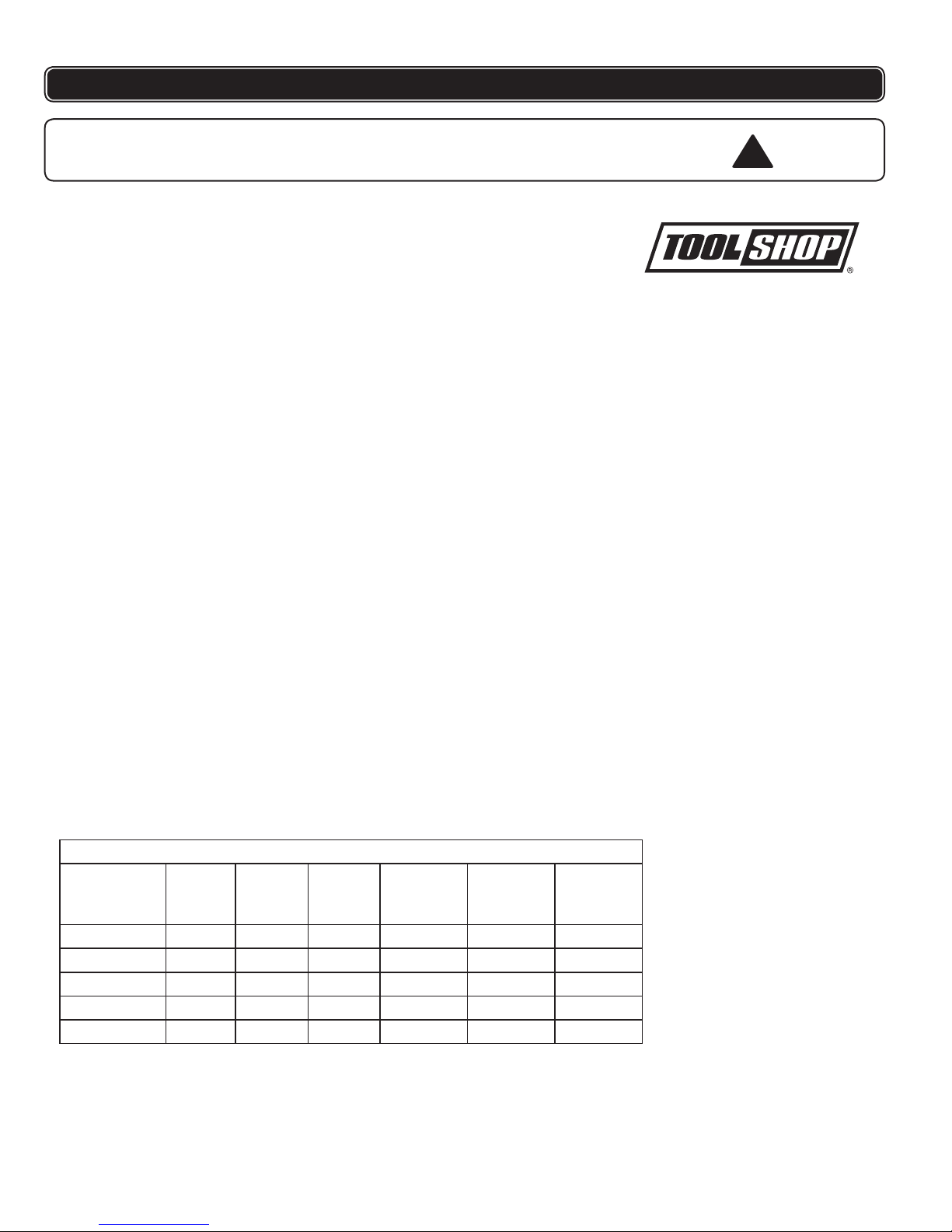
Recommended Minimum Wire Gauge for Extension Cords
Amps
from Tool
Nameplate
7.62 m
(25') long
15.24 m
(50') long
22.86 m
(75') long
30.48 m
(100') long
45.72 m
(150') long
60.96 m
(200') long
0 - 5 amps 16 ga. 16 ga. 16 ga. 14 ga. 12 ga. 12 ga.
5.1 - 8 amps 16 ga. 16 ga. 14 ga. 12 ga. 10 ga. Do Not Use
8.1 - 12 amps 14 ga. 14 ga. 12 ga. 10 ga. Do Not Use Do Not Use
12.1 - 15 amps 12 ga. 12 ga. 10 ga. 10 ga. Do Not Use Do Not Use
15.1 - 20 amps 10 ga. 10 ga. 10 ga. Do Not Use Do Not Use Do Not Use
!
1. KEEP WORK AREA CLEAN. Cluttered areas can cause injuries.
2. CONSIDER WORK AREA ENVIRONMENT. Don’t use power tools in damp,
wet, or poorly lit locations. Don’t expose tools to the rain. Keep the work area
well lit. Don’t use tools in the presence of flammable gases or liquids.
3. KEEP CHILDREN AND BYSTANDERS AWAY. All children should be kept
away from the work area. Don’t let them handle machines, tools or extension
cords. Bystanders can be a distraction and can be injured.
4. GROUNDED TOOLS must be plugged into an outlet that is properly
installed and grounded. Grounding provides a low-resistance path to carry
electricity to the ground away from the operator, should the tool malfunction elec--
trically. Do not remove the grounding prong from the plug or alter the plug in
any way. If in doubt as to whether the outlet is properly grounded according
to code, check with a qualified electrician.
5. OBSERVE PROPER PRECAUTIONS REGARDING DOUBLE INSULA-
TION. This tool is double insulated. It is equipped with a polarized plug.
One blade is wider than the other, so it will fit into a polarized outlet only one
way. If you have difficulty inserting the plug, try reversing it. If it still doesn’t
fit , do not alter the plug; have a qualified electrician install a polarized outlet.
6. GUARD AGAINST ELECTRIC SHOCK. Prevent body contact with grounded
surfaces: pipes, radiators, ranges, and refrigerator enclosures. When your
body is grounded the risk of electric shock increases. When working wher-
ever “live” electrical wires may be encountered, try to ascertain whether
there is a danger of shock. DO NOT TOUCH ANY METAL PARTS
OF THE TOOL while using it. Hold the tool only by the plastic grip to prevent
electric shock if you contact a live wire.
7. DO NOT MISUSE THE CORD. Never carry your tools by the cord or pull on
the cord to unplug it. Protect the cord from potential sources of damage:
heat, oil & solvents, sharp edges, or moving parts. Replace damaged cords
immediately.
8. WHEN WORKING OUTDOORS, USE AN OUTDOOR-RATED EXTENSION
CORD. An extension cord rated for outdoor use must be marked “W-A” or
“W”.
9. DO NOT EXPOSE ELECTRICAL POWER TOOLS TO MOISTURE. Rain or
wet conditions can cause water to enter the tool and lead to electric shock.
10. ENSURE THE EXTENSION CORD YOU USE IS OF SUFFICIENT GAUGE
FOR ITS LENGTH.
11. STORE IDLE EQUIPMENT. Store equipment in a dry area to inhibit rust.
Equipment also should be in a high location or locked up to keep out of
reach of children.
12. DON’T FORCE THE TOOL. It will do the job better and more safely at the
rate for which it was intended.
13. USE THE RIGHT TOOL. Don’t force a small tool or attachment to do the
work of a larger industrial tool. Don’t use a tool for a purpose for which it was
not intended.
2

3
ALWAYS CHECK THE SPEED RATING OF ACCESSORIES. This tool will spin
accessories at 3,000 rpm. Accessories not rated for speeds this high will very likely
fly apart and could cause serious injury.
IMPORTANT SAFETY INSTRUCTIONS
SAFETY PRECAUTIONS FOR 1/2 INCH HAMMER DRILL
SPECIFICATIONS
15. USE EYE PROTECTION. Use a full-face mask if the work you’re doing
produces metal filings, dust or wood chips. Goggles are acceptable in other
situations. Wear a clean dust mask if the work involves creating a lot of fine
or coarse dust.
16. SECURE WORK. Use clamps or a vise to hold the work, this frees both
hands to operate the tool.
17. DON’T OVERREACH. Keep proper footing and balance at all times. Do not
reach over or across machines that are running.
18. MAINTAIN TOOLS. Keep tools sharp and clean for better and safer
performance. Follow instructions for lubricating and changing accessories.
For safe performance. Keep handles dry, clean and free from oil and grease.
19. AVOID UNINTENTIONAL STARTING. Be sure the switch is in the OFF posi-
tion before plugging in.
20. ALWAYS CHECK AND MAKE SURE TO REMOVE ANY ADJUSTING KEYS
OR WRENCHES before turning the tool on. Left attached, these parts can fly
off a moving part and result in injury.
21. DO NOT USE THE TOOL IF IT CANNOT BE SWITCHED ON OR OFF.
Have your tool repaired before using it.
22. DISCONNECT THE PLUG FROM THE POWER SOURCE BEFORE MAKING
ANY ADJUSTMENTS.
Changing attachments or accessories can be dangerous
if the tool could accidentally start.
23. STAY ALERT. Watch what you are doing & use common sense. Don’t operate
any tool when you are tired.
24. CHECK FOR DAMAGED PARTS. Before using this tool, any part that is
damaged should be carefully checked to determine that it will operate prop-
erly and perform its intended function. Check for alignment of moving parts,
binding of moving parts, breakage of parts, mountings, and other conditions
that may affect its operation. Inspect screws and tighten any ones that are
loose. Any part that is damaged should be properly repaired or replaced by
an authorized service center unless otherwise indicated elsewhere in the in-
struction manual. Have defective switches replaced by an authorized service
center. Don’t use the tool if switch does not turn it on and off properly.
25. REPLACEMENT PARTS. When servicing, use only identical replacement
parts.
26. SERVICE AND REPAIRS should be made by qualified repair technicians at
an authorized repair center. Improperly repaired tools could cause serious
shock or injury.
14. DRESS PROPERLY. Don’t wear loose clothing or jewelry; they can be
caught in moving parts. Protective, non-electrically conductive gloves, protective
eyewear and non-skid footwear are recommended. Wear protective hair
covering to contain long hair and keep yourself from harm.
Voltage: 120 volts AC, 60Hz.
Current rating: 6.7 Amp
No load speed: 0-3,000 RPM
No load impacts: 0-48,000 BPM
1/2” keyless chuck

4
FRANÇAIS
This tool is designed for drilling into almost any material. For drilling into wood,
metal, and plastics, use it in the regular (non-hammer) setting. For drilling holes
in stone or concrete, use special masonry drill bits and the hammer setting.
1. Depth gauge rod
2. Depth gauge clamping wing nut
3. Chuck
4. Side handle
5. Chuck key
6. Padded handle
7. Lock-on button
8. Speed control dial
9. Variable speed trigger switch
10. Forward/Reverse switch
11. Drilling and impact mode selector switch
OPERATING PROCEDURES
Operating the chuck
1. Be sure the drill is disconnected from power source.
2. Open the chuck, using the chuck key, until it accepts the drill bit or accessory
shaft, up to 13mm (1/2”) in diameter.
3. Close the chuck and tighten it using the chuck key
4. Remove the chuck key before using the drill.
Side handle
1. Loosen the wing nut that joins the side handle to the drill.
2. Rotate the handle to a position that will allow you to hold the tool firmly and
comfortably.
3. Re-tighten the wing nut.
Depth Gauge Stop Rod
1. Loosen the wing nut that joins the side handle to the depth stop rod.
2. Slide the rod to the position as indicated on its scale that will stop the drills
forward motion when the desired drilling depth is reached.
3. Re-tighten the wing nut.
FUNCTIONAL DESCRIPTION
Running the hammer drill
1. Plug the tool into a power source.
2. Hold the tool irmly. The farther you despress the triger the faster the speed. The
maximum speed is adjustable by rotating the speed adjustment wheel on the
trigger.
3. To maintain a certain speed after you have set your speed dial(loacted on the trigger)
engage the lock-on button on the left side of the handle when squeezing the trigger switch.
4. To disengage the lock-on button, squeeze the trigger again.
1
211
3
45
6
7
8
9
10

5
Forward-Reverse
To change the chuck rotation direction, move the lever above the trigger to the
other side.
Setting the direction switch to the right causes the drill to turn clockwise, for
normal drilling.
The direction switch moved to the left will cause the drill to run in reverse
(counterclockwise) direction, backing drill bits and screws out of their holes.
Hammer Drill Setting
To change the drill from regular drilling to the hammer drilling, wait until the drill has
stopped turning, and slide the drilling and impact mode selector switch to the right,
exposing the hammer pictograph. This will cause the drill to use percussion as
well as turning action. This percussion causes the tip of the drill bit to break up
the material it contacts, while the turning action removes the debris created from
the contact point at the drill tip. The percussion varies from 0 to 48,000 beats per
minute. Be aware that the force of the impact tends to diminish as the number of
beats per minute increases.
Do not move the drilling and impact mode selector switch while the drill is turning.
WARNING: Turn off your drill at once, unplug and inspect it for serious problems if:
Moving parts get stuck
Speed drops to an abnormally low level
The motor housing gets hot
Sparks or odors emit from the casing
Metal Drilling
NOTE: For maximum performance, use high speed steel bits for metal or steel
drilling.
1. Move the drilling and impact mode selector switch to the drilling mode.
2. Use a center punch to mark the hole location on the workpiece.
3. Begin drilling at a very low speed to prevent the bit from slipping off the starting
point.
4. Maintain a speed and pressure which allows drilling without overheating the bit.
Applying too much pressure may overheat the drill, wear out the bearing, bend
or burn bits, produce off-center or irregular shaped holes.
5. When drilling large holes in metal it is highly recommended to drill with a small
bit at first, and finish with a larger bit. It is also recommended to use a cutting
lubricant to improve drilling action and increase bit life.
Wood Drilling
NOTE: For maximum performance, use high speed steel bits for wood drilling.
1. Move the drilling and impact mode selector switch to the drilling mode.
2. Secure the workpiece to prevent it from turning when drilling which may cause
injury.
3. Begin drilling at a very low speed to prevent the bit from slipping off the starting
OPERATING PROCEDURES
!
!
!
Table of contents
Other Toolshop Drill manuals


