Toolshop 241-9826 User manual
1/2” 4.5 AMP HAMMER DRILL
241-9826
SAVE THIS MANUAL
You will need this manual for safety instructions, operating procedures and warranty.
Put it and the original sales receipt in a safe dry place for future reference.
For questions about this product, Please call 1-866-915-8626
Operator’s Manual

IMPORTANT SAFETY INSTRUCTIONS
2
WARNING:When using electric tools, machines or equipment, basic safety
shock, and personal injury. !
READ ALL INSTRUCTIONS BEFORE USING THIS TOOL
1. KEEP WORK AREA CLEAN. Cluttered areas can cause injuries.
2. CONSIDER WORK AREA ENVIRONMENT. Don’t use power tools in damp,
wet, or poorly lit locations. Don’t expose tools to the rain. Keep the work area
3. KEEP CHILDREN AND BYSTANDERS AWAY.
away from the work area. Don’t let them handle machines, tools or extension
cords.
4.
5. OBSERVE PROPER PRECAUTIONS REGARDING DOUBLE INSULA-
TION.
6. GUARD AGAINST ELECTRIC SHOCK.
electric shock if you contact a live wire.
7. DO NOT MISUSE THE CORD.
immediately.
8. WHEN WORKING OUTDOORS, USE AN OUTDOOR-RATED EXTENSION
CORD.
9. ENSURE THE EXTENSION CORD YOU USE IS OF SUFFICIENT GAUGE
FOR ITS LENGTH.
10. STORE IDLE EQUIPMENT.
reach of children.
11. DON’T FORCE THE TOOL. It
rate for which it was intended.
12. USE THE RIGHT TOOL. Don’t force a small tool or attachment to do the
not intended.
13. DRESS PROPERLY.
Recommended Minimum Wire Gauge for Extension Cords
Amps
from
Tool Nameplate
25’ length 50’ length 75’ length 100’ length 150’ length 200’ length
0-5 amps
5.1-8 amps
8.1-12 amps
12.1-15 amps
15.1-20 amps
GROUNDED TOOLS MUST BE PLUGGED INTO AN OUTLET THAT IS
PROPERLY INSTALLED AND GROUNDED.
Bystanders can be a distraction and could be injured.
There should be a low-resistance path to carry
3
IMPORTANT SAFETY INSTRUCTIONS
14. USE EYE PROTECTION.
or coarse dust.
15. SECURE WORK.
16. DON’T OVERREACH.
17. MAINTAIN TOOLS.
18. AVOID UNINTENTIONAL STARTING. Be sure the switch is in the OFF posi
20. DO NOT USE THE TOOL IF IT CANNOT BE SWITCHED ON OR OFF.
21. DISCONNECT THE PLUG FROM THE POWER SOURCE BEFORE MAKING
ANY ADJUSTMENTS.
if the tool accidentally starts.
22. STAY ALERT.
23. CHECK FOR DAMAGED PARTS.
center. Don’t use the tool if switch does not turn it on and o
shock or injury.
ff properly.
24. REPLACEMENT PARTS.
parts.
25. SERVICE AND REPAIRS
19. ALWAYS CHECK AND MAKE SURE TO REMOVE ANY ADJUSTING KEYS OR
WRENCHES BEFORE TURNING THE TOOL ON.
Use clamps or a vise to hold the work, this will free both
hands to operate the tool.
, k
Watch what you are doing and use common sense.
Do not operate any tool when you are tired, or using medication which can
make you drowsy.
or binding of
, any or mountings, or other conditions
that may affect safe
,

4
1. Depth gauge rod
2. Depth gauge clamp
3. Chuck
4. Side handle
5. Chuck key
6. Lock-on button
7. Speed control dial
8. Variable speed trigger switch
9. Forward/Reverse switch
10. Drilling and impact mode selector switch
OPERATING PROCEDURES
Operating the chuck
1. Be sure the drill is disconnected from power source.
2. Open the chuck, using the chuck key, until it accepts the drill bit or accessory
shaft, up to 13mm (1/2”) in diameter.
3. Close the chuck and tighten it using the chuck key
4. Remove the chuck key before using the drill.
Side handle
1. Loosen the grip on the Side Handle and slide Side Handle clamp over and
behind the Chuck until it is set against housing.
2. Rotate the Side Handle until it is in desired orientation.
3. Rotate Side Handle grip clockwise to secure the clamp.
Install the depth gauge
1. Loosen the Side Handle.
2. Slide the Depth Gauge into the gauge hole.
3. Set Depth Gauge to required depth.
4. Retighten grip to fasten Depth Gauge into place.
FUNCTIONAL DESCRIPTION
Running the hammer drill
1. Plug the tool into a power source.
2. Hold the tool firmly. The farther you despress the trigger the faster the speed. The
maximum speed is adjustable by rotating the speed adjustment wheel on the
trigger.
3. To maintain a certain speed after you have set your speed dial(located on the trigger)
engage the lock-on button on the left side of the handle when squeezing the trigger switch.
4. To disengage the lock-on button, squeeze the trigger again.
1
210
3
4
5
6
78
9
SPECIFICATIONS
■Voltage: 120 volts AC, 60Hz.
■Current rating: 4.5 Amp
■No load speed: 0-2,800 RPM
No load impacts: 0-40,000 BPM
■1/2'' keyed chuck
5
Forward-Reverse
To change the chuck rotation direction, press the Forward-Reverse switch.
For clockwise (forward) rotation, push it from the right side.
For counterclockwise (reverse) rotation, push it from the left side.
Regular drilling and Hammer drilling mode
To change the drill from regular drilling to the hammer drilling, wait until the drill has
stopped turning, and slide the drilling and impact mode selector switch to the left,
the side with the hammer drill mode symbol. This will cause the drill to use
percussion as well as turning action. This percussion causes the tip of the drill bit to
break up the material it contacts, while the turning action removes the debris created
from the contact point at the drill tip. The percussion varies from 0 to 40,000 beats per
minute. Be aware that the force of the impact tends to diminish as the number of
beats per minute increases.
Do not move the drilling and impact mode selector switch while the drill is turning.
WARNING: Turn off your drill at once, unplug and inspect it for serious problems if:
Moving parts get stuck
Speed drops to an abnormally low level
The motor housing gets hot
Sparks or odors emit from the casing
Metal Drilling
NOTE: rofstibmuinatitrostibleetsdeepshgihesu,ecnamrofrepmumixamroF
metal or steel drilling.
1. Move the drilling and impact mode selector switch to the regular drilling mode.
2. Use a center punch to mark the hole location on the workpiece.
3. Begin drilling at a very low speed to prevent the bit from slipping off the starting
point.
4. Maintain a speed and pressure which allows drilling without overheating the bit.
Applying too much pressure may overheat the drill, wear out the bearing, bend
or burn bits, produce off-center or irregular shaped holes.
5. When drilling large holes in metal it is highly recommended to drill with a small
bit at first, and finish with a larger bit. It is also recommended to use a cutting
lubricant to improve drilling action and increase bit life.
Wood Drilling
NOTE: For maximum performance, use high speed steel bits for wood drilling.
1. Move the drilling and impact mode selector switch to the regular drilling mode.
2. Secure the workpiece to prevent it from turning when drilling which may cause
injury.
3. Begin drilling at a very low speed to prevent the bit from slipping off the starting
OPERATING PROCEDURES
!
!
!
point. Increase the speed as the drill bit bites into the material.
This tool is designed for drilling into almost any material. For drilling into wood,
metal, and plastics, use it in the regular (non-hammer) setting. For drilling holes
in stone or concrete, use special masonry drill bits and the hammer setting.
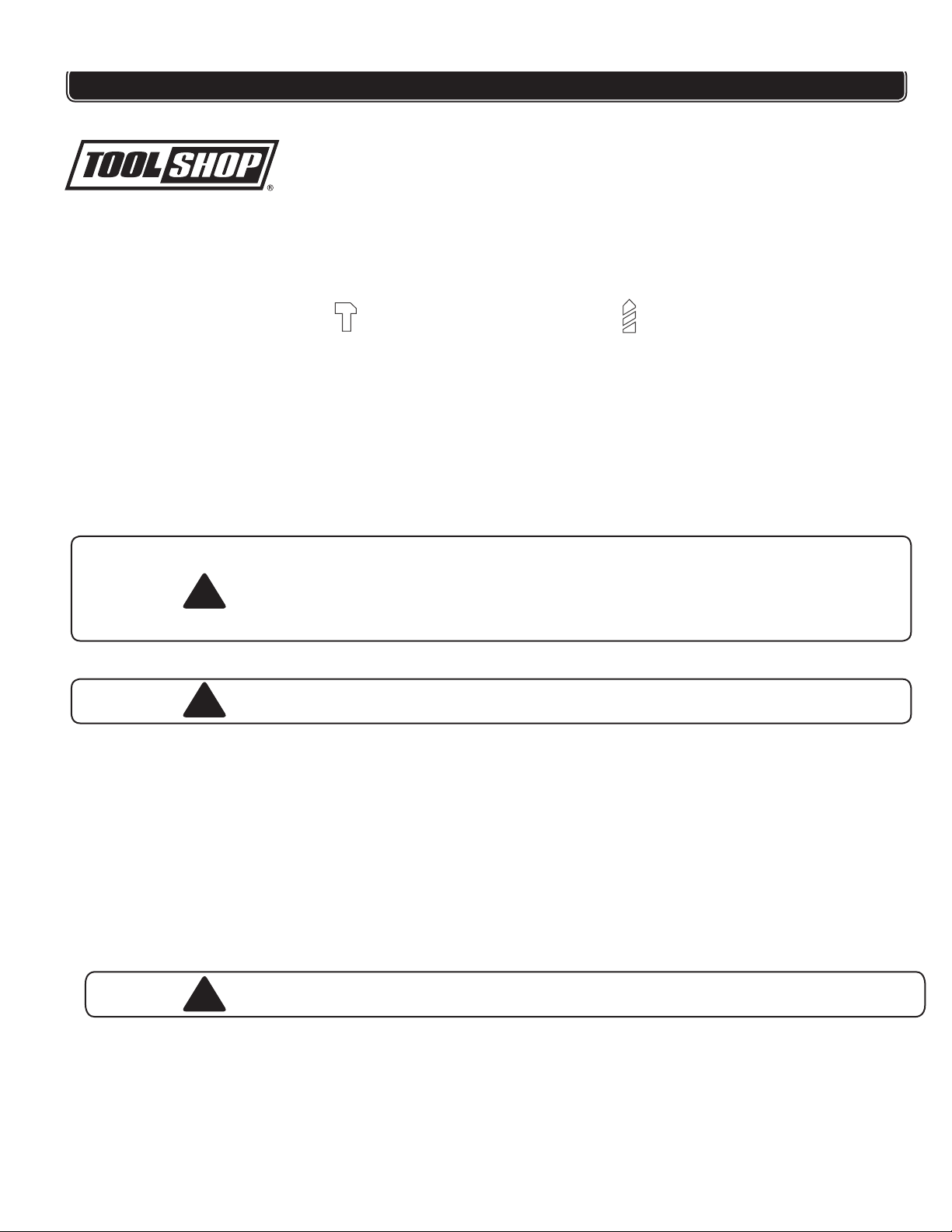
Set to Hammer Drill for masonry bits.
(Hammer drilling mode) (Regular drilling mode)
Set to Drill for other bits.

6
4. When drilling through holes, place a block of wood behind the workpiece to
prevent ragged or splintered edges on the back side of the hole.
5. Do not lock the trigger in the “ON” position if the drill may need to be stopped
suddenly.
Masonry Drilling
NOTE: For maximum performance use tungsten carbide-tipped masonry impact
bits when drilling holes in concrete, brick or tile.
1. Move the drilling and impact mode selector switch to the hammer drilling mode.
2. Apply light pressure and medium speed for best results in brick.
3. Apply additional pressure and high speed for hard materials such as concrete.
4. When drilling in tile, practice on a scrap piece to determine the best speed and
pressure.
NOTE: When drilling into tile, a special tile cutting bit may be required.
MAINTENANCE
Keep the tool housing clean and free of oil and grease by using mild soap and a
damp (not wet) cloth.
Inspect the cord regularly and have it replaced by an authorized repair facility if
it is damaged.
Lubrication for this tool is done at the factory and should not be necessary
again under normal use.
An authorized repair center should do any repairs, modification, or mainte-
nance that involves disassembling the tool.
Any damage to the tool should be corrected at an authorized repair center.
OPERATING PROCEDURES
!
!
Keep the vents clear of dust and debris. This will help prevent possible electri -
cal shorts and ensure proper cooling.

7
PARTS LIST
Please refer to Schematic Drawing, page 8
Part Description Qty
1 Screw M5×25 1
2 Chuck 1
3 Spindle 1
4 Woodruff key 1
5Ball Φ5 1
6 Spring 1
7 Bearing 6201 1
8 Ring 1
9 Gear 1
10 Retaining Ring 1
11 Arm 1
12 Function Switch 1
13 Impact Block 1
14 Bearing 1
15 Rotor 1
16 Bearing 1
17 Stator 1
Part Description Qty
18 Brush Holder 2
19 Carbon Brush 2
20 Brush Cap 2
21 Forward/Reverse Button 1
22 Right Housing 1
23 Trigger 1
24 Depth Gauge Knob 1
25 Depth Gauge 1
26 Side Handle 1
27 Side Handle Knob 1
28 Cord Clip 1
29 Left Housing 1
30 Label 2
31 Screw ST 4.2*16 12
32 Chuck Key 1
33 Cord Sheath 1
34 Power Cord 1

SCHEMATIC DRAWING
!
8
WARNING Repairs should be made by an authorized repair center. Do not
this power tool tatcatnoC.
for questions regarding this power tool.
1-866-915-8626
open or disassemble
25
26
33
34
23
24
27

9
TOOL SHOP®
1-YEAR LIMITED WARRANTY:
This
TOOL SHOP®
brand power tool carries a 1-Year Limited Warranty to the
original purchaser. If the tool fails within one (1) year from the date of
purchase, simply bring this tool with your original sales receipt back to your
nearest
MENARDS
®
retail store. At its discretion,
TOOL SHOP®
agrees to
have the tool replaced with the same or similar
TOOL SHOP®
product free of
charge, within the stated warranty period, when returned by the original
purchaser with original sales receipt. Notwithstanding the foregoing, this
limited warranty does not cover any damage that has resulted from abuse or
misuse of the Merchandise. This warranty: (1) excludes expendable parts
including but not limited to blades, belts, bits, light bulbs, and/or batteries;(2)
shall be void if this tool is used for commercial and/or rental purposes;and (3)
does not cover any losses, injuries to persons/property or costs. This
warranty does give you specific legal rights and you may have other rights,
which vary from state to state. Be careful, tools are dangerous if improperly
used or maintained. Seller’s employees are not qualified to advise you on the
use of this Merchandise. Any oral representation(s) made will not be binding
on seller or its employees. The rights under this limited warranty are to the
original purchaser of the Merchandise and may not be transferred to any
subsequent owner. This limited warranty is in lieu of all warranties,
expressed or implied including warranties or merchantability and fitness for a
particular purpose. Seller shall not beliable for any special, incidental, or
consequential damages. The sole exclusive remedy against the seller will be
for the replacement of any defects as provided herein, as long as the seller is
willing or able to replace this product or is willing to refund the purchase price
as provided above. For insurance purposes, seller is not allowed to
demonstrate any of these power tools for you.
For questions / comments, technical assistance or repair parts –
Please call toll free at: 1-866-915-8626
(M-F
9
am – 5pm EST)
SAVE YOUR RECEIPTS. THIS WARRANTY IS VOID WITHOUT THEM.
1/2” 4.5AMP HAMMER DRILL WARRANTY
Table of contents
Other Toolshop Drill manuals


