Toolshop 241-9885 User manual

3/8” ANGLE DRILL
241-9885
SAVE THIS MANUAL
You will need this manual for safety instructions, operating procedures and warranty.
Put it and the original sales receipt in a safe dry place for future reference.
Operator’s Manual

2
IMPORTANT SAFETY INSTRUCTIONS
WARNING: When using electric tools, machines or equipment, basic safety
precautions should always be followed to reduce the risk of re, electric shock, and
personal injury.
READ ALL INSTRUCTIONS BEFORE USING THIS TOOL
1. KEEP WORK AREA CLEAN. Cluttered areas invite injuries.
2. CONSIDER WORK AREA ENVIRONMENT. Don’t use power tools in damp,
wet, or poorly lit locations. Don’t expose your tool to rain. Keep the work area
well lit. Don’t use tools in the presence of ammable gases or liquids.
3. KEEP CHILDREN AND BYSTANDERS AWAY. All children should be kept
away from the work area. Don’t let them handle machines, tools or extension
cords. Visitors can be a distraction and are difcult to protect from injury.
4. GROUNDED TOOLS must be plugged into an outlet that itself is properly
installed and grounded. Grounding provides a low-resistance path to carry
electricity to ground away from the operator, should the tool malfunction electri-
cally. Do not remove the grounding prong from the plug or alter the plug in
any way. If in doubt as to whether the outlet is properly grounded according to
code, check with a qualied electrician.
5. OBSERVE PROPER PRECAUTIONS REGARDING DOUBLE INSULATION.
This tool is double insulated. It is equipped with a polarized plug. One blade
is wider than the other, so it will t into a polarized outlet only one way. If you
have difculty inserting the plug, try reversing it. If it still doesn’t t , do not alter
the plug; have a qualied electrician install a polarized outlet.
6. GUARD AGAINST ELECTRIC SHOCK. Prevent body contact with grounded
surfaces: pipes, radiators, ranges, and refrigerator enclosures. When your body
is grounded the risk of electric shock increases. When working wherever “live”
electrical wires may be encountered, try to ascertain whether there is a danger
of shock. Even so, DO NOT TOUCH ANY METAL PARTS OF THE TOOL while
using it. Hold the tool only by the plastic grip to prevent electric shock if you
contact a live wire.
7. DO NOT ABUSE THE CORD. Never carry power tool by the cord or pull on the
cord to unplug it. Protect the cord from potential sources of damage: heat, oil &
solvents, sharp edges, or moving parts. Replace damaged cords immediately.
8. WHEN WORKING OUTDOORS, USE AN OUTDOOR-RATED EXTENSION-
CORD. An extension cord rated for outdoor use must be marked “W-A” or “W”.
9. DO NOT EXPOSE ELECTRICAL POWER TOOLS TO MOISTURE. Rain or
wet conditions can cause water to enter the tool and lead to electric shock.
10. ENSURE THE EXTENSION CORD YOU USE IS OF SUFFICIENT GAUGE
FOR ITS LENGTH.
Recommended Minimum Wire Gauge for Extension Cords
Amps
from
Tool Nameplate
25’ length 50’ length 75’ length 100’ length 150’ length 200’ length
0-5 amps 16 ga. 16 ga. 16 ga. 14 ga. 12 ga. 12 ga.
5.1-8 amps 16 ga. 16 ga. 14 ga. 12 ga. 10 ga. Do Not Use
8.1-12 amps 14 ga. 14 ga. 12 ga. 10 ga. Do Not Use Do Not Use
12.1-15 amps 12 ga. 12 ga. 10 ga. 10 ga. Do Not Use Do Not Use
15.1-20 amps 10 ga. 10 ga. 10 ga. Do Not Use Do Not Use Do Not Use
11. STORE IDLE EQUIPMENT. Store equipment in a dry area to inhibit rust. Equip-
ment also should be in a high location or locked up to keep out of reach of
children.
12. DON’T FORCE THE TOOL. It will do the job better and more safely at the rate
for which it was intended.
!

15. USE EYE PROTECTION. Use a full-face mask if the work you’re doing produc
es metal lings, dust or wood chips. Goggles are acceptable in other situations.
Wear a clean dust mask if the work involves creating a lot of ne or coarse
dust.
16. SECURE WORK. Use clamps or a vise to hold the work. It’s safer than using
your hands and it frees both hands to operate the tool.
17. DON’T OVERREACH. Keep proper footing and balance at all times. Do not
reach over or across machines that are running.
19. AVOID UNINTENTIONAL STARTING. Be sure the switch is in the OFF position
before plugging in.
20. ALWAYS CHECK AND MAKE SURE TO REMOVE ANY ADJUSTING KEYS
OR WRENCHES before turning the tool on. Left attached, these parts can y
off a rotating part and result in personal injury.
21. DO NOT USE THE TOOL IF IT CANNOT BE SWITCHED ON OR OFF. Have
your tool repaired before using it.
22. DISCONNNECT THE PLUG FROM POWER BEFORE MAKING ANY AD-
JUSTMENTS. Changing attachments or accessories can be dangerous if the
tool could accidentally start.
23. STAY ALERT. Watch what you are doing & use common sense. Don’t operate
any tool when you are tired.
24. CHECK FOR DAMAGED PARTS. Before using this tool, any part that is dam-
aged should be carefully checked to determine that it will operate properly and
perform its intended function. Check for alignment of moving parts, binding
of moving parts, breakage of parts, mountings, and other conditions that may
affect its operation. Inspect screws and tighten any ones that are loose. Any
part that is damaged should be properly repaired or replaced by an authorized
service center unless otherwise indicated elsewhere in the instruction manual.
Have defective switches replaced by an authorized service center. Don’t use
the tool if switch does not turn it on and off properly.
25. REPLACEMENT PARTS. When servicing, use only identical replacement parts.
26. SERVICE AND REPAIRS should be made by qualied repair technicians at an
authorized repair centre. Improperly repaired tools could cause serious shock
or injury
ALWAYS CHECK THE SPEED RATING OF ACCESSORIES. This tool will spin
accessories at up to rpm. Accessories not rated for speeds this high will
very likely y apart and could cause serious injury.
IMPORTANT SAFETY INSTRUCTIONS
!
SAFETY PRECAUTIONS
13. USE THE RIGHT TOOL. Don’t force a small tool or attachment to do the work
of a larger industrial tool. Don’t use a tool for a purpose for which it was not
intended.
14. DRESS PROPERLY. Don’t wear loose clothing or jewelry; they can be caught
in moving parts. Protective, non-electrically conductive gloves and non-skid
footwear are recommended when working. Wear protective hair covering to
contain long hair and keep it from harm.
1400
18. MAINTAIN TOOLS WITH CARE. Keep tools sharp and clean for better and
safer performance. Follow instructions for lubricating and changing accessories.
For safe performance, keep handles dry, clean and free from oil and grease.

4
Voltage: 120 volts AC, 60Hz.
Current rating: 3.8 amps
No load speed: 0-1400 rpm
3/8”-10 mm keyless chuck
Trigger-controlled variable speed
Convenient above-the-trigger reverse switch
Lock-on button
A. Variable speed trigger
B. Forward / Reverse / Neutral switch
C. 3/8” Keyless chuck
D. Chuck lock button
E. Trigger-lock button
F. Rubber grip handle
G. Motor brush dust cover cap
OPERATING THE CHUCK
Be sure the drill is disconnected from power.
The angle drill is equipped with a 3/8” keyless chuck that will accept drill bits with
a 1/16 inch to 3/8 inch shank.
Installing a drill bit into the drill chuck requires the use of the chuck lock button.
Always make sure the drill bits are firmly secured into the drill chuck prior to using
RUNNING THE DRILL
1. Plug in the tool.
2. Hold the tool rmly. Squeezing the trigger more will increase the speed.
3. To maintain a certain speed when set on the adjustment wheel, engage the
trigger-lock button on the left side of the handle when squeezing the trigger
switch.
4. To disengage the trigger-lock button, squeeze the trigger.
To change the chuck rotation direction, move the rotation direction switch above the
trigger to the other side. Setting the direction switch to the right causes the drill to
turn clockwise, for normal drilling. The direction switch moved to the left will cause
the drill to run in reverse (counterclockwise) direction, backing drill bits and screws
out of their holes.
Warning: Turn off your drill at once, unplug and inspect it for serious problems if:
nMoving parts get stuck
nSpeed drops to an abnormally low level
nThe motor housing gets hot
nSparks or odors emit from the casing
!
SPECIFICATIONS
OPERATING PROCEDURES
A
B
C
D
E
F
G
the drill.
FUNCTION DESCRIPTION
5
Metal Drilling
Use a sharp drill bit especially designed to cut the material you are working on. It
is recommended you use a cutting luid on the metal surface to avoid heat build-up.
MAINTENANCE
OPERATING PROCEDURES
CAUTION! Always be sure that the tool is switched off and unplugged before at-
tempting to perform inspection or maintenance.
Inspect the tool before each use. Inspect the switch, the power plug and cord
assembly for damage. Check for loose screws, misalignment, binding of
moving parts, broken, cracked or improper mounting of the bits and attach-
ments, broken parts and any other condition that may affect safe operation. If
abnormal noise or vibration occurs, turn off the tool immediately and have the
problem corrected before further usage.
Do not use damaged equipment or serious injury could result.
Avoid overloading your angle drill. Do not force the tool. It will become hot and
lose efciency. Running it free of load for a minute or two will allow it to cool
itself to normal temperature.
Brushes: This tool has two Carbon Motor Brushes (See Schematic Draw-
ing #19 on page 6) that should be periodically examined for wear. After long
use, the brushes in your tool may become worn. This may be evident from a
burning smell or excessive sparking visible through the ventilation holes while
the tool is running. To inspect or replace the carbon motor brushes:
1. Unscrew the black plastic Motor Brush Cover (See Schematic Drawing #18
on page 6) using a slot screwdriver slowly remove the cover as the brushes
are spring-loaded and may jump free, strike a hard surface, and chip.
!
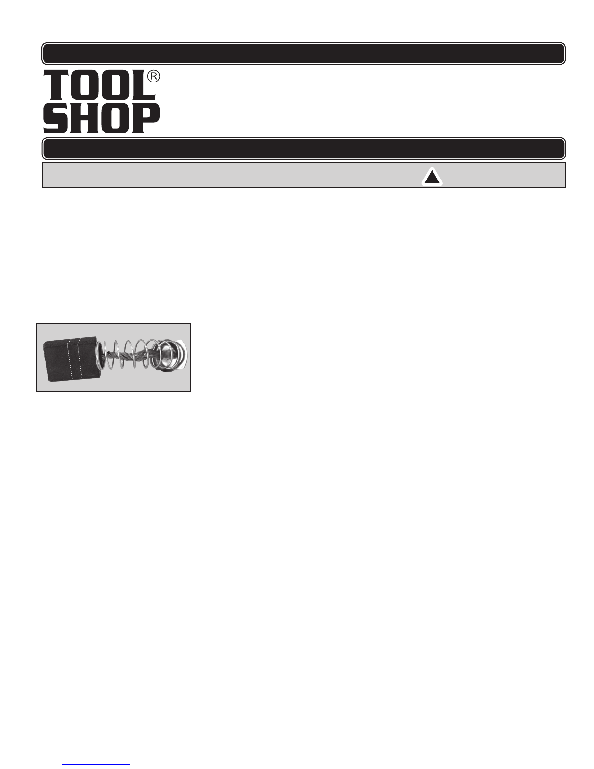
2.Remove the brushes and examine the black rectangular carbon portions.
Examine the concave, wearing surfaces. They should be smooth and clean.
If there are large scratch marks, chips broken off and other damage, replace
both brushes immediately. When new, these are about 7/16” long (see fig.
at right). We recommend they be replaced when worn about 1/2way down
or at about 1/4”remaining.
After this point, they are not held at a steady angle
and constant pressure.
3.When the brushes are worn to 1/3 of their original length, about 1/8”, they
must be replaced or damage to the motor could result.
4. Insert the brushes so that the rectangular carbon portion slides in the slots in
the brass holders.
5. Replace the black plastic Motor Brush Cover over the brass cap, screwing it
in by hand to hold it in place.
7. Screw it down properly with a slot screwdriver. Do not over-tighten.
8. Always replace both brushes at the same time.
9. Keep the carbon brushes clean and free to slip in the holders.
When first using the tool with fresh brushes, you will notice a certain amount of
sparking. This is normal and will continue until the brush contact surface attains
a correct concave profile to match the rotor on the motor.
Keep the tool housing clean; free of oil, and grease. If necessary, use mild
soap and a damp (not wet) cloth. DO NOT let solvents like brake fluid, gaso-
line, petroleum-based products, etc., contact plastic parts of the housing.
Cleaning with these substances can harm the plastic and compromise the
integrity of the double insulating system.
Clean the tool of all sawdust. Keep the vents clear of dust and debris. Use a
brush, soft cloth, or a vacuum cleaner. This will help prevent possible electrical
shorts and ensure proper cooling.
Use care to see that the motor winding does not become damaged or wet with
oil or water.
An authorized repair center should do any repairs, modification, or
maintenance that involve opening or disassembling the tool.
Any damage to the tool should be corrected at an authorized repair center.
6
33
34
35
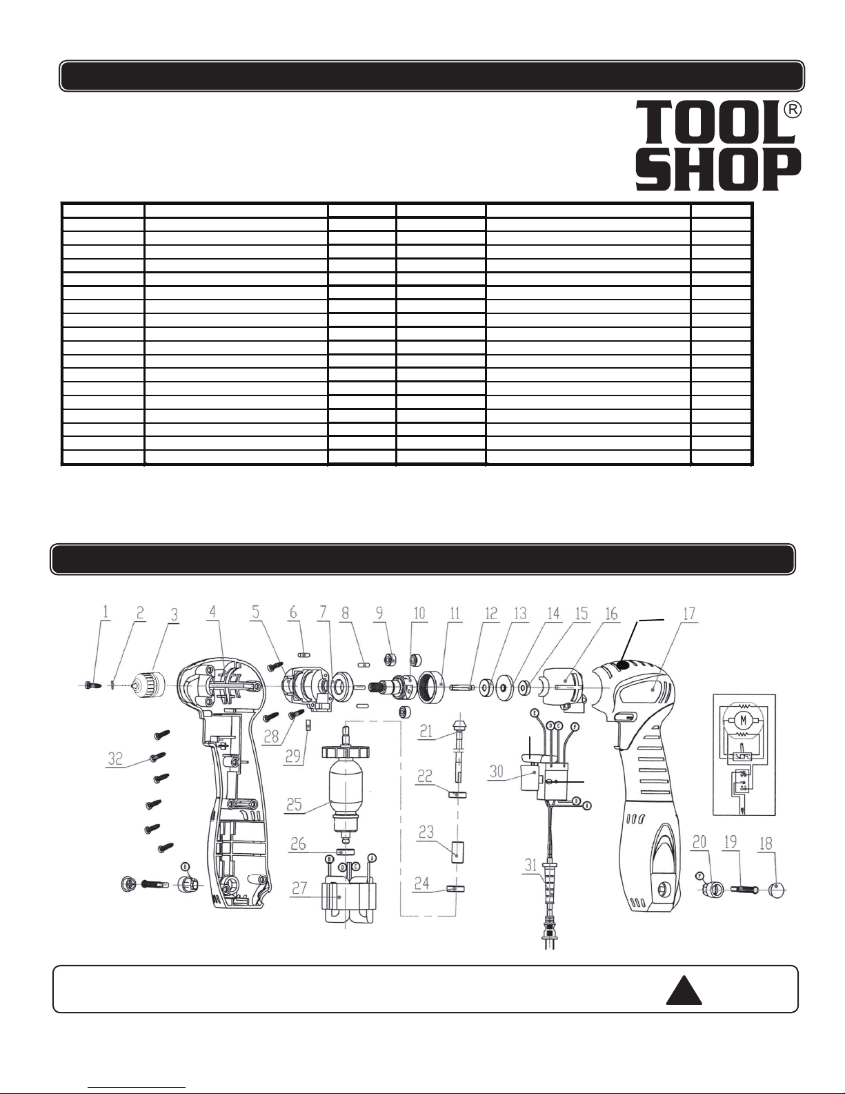
PARTS LIST
SCHEMATIC DRAWING
Part # Description Qty. Part # Description Qty.
2hsurBnobraC911)tfeL02x5M(wercS1
2redloHhsurB021)5(rehsaWgnirpS2
1)1Z(eldnipSraeG121kcuhCllirD3
4 Motor Housing 1 22 Ball Bearing (626) 1
1gnihsuBkniL321gnisuoHraeG5
1)806(gniraeBllaB421niPrebbuR6
1erutamrA521)2006(gniraeBllaB7
1)706(gniraeBllaB623niP8
1dleiF721)4Z(raeG9
3)02x4M(wercS821eldnipS01
1niPrebbuR921)5Z(raeG11
1reggirT031)3Z(eldnipSraeG21
13 Ball Bearing (626) 1 31 Power Cord/Plug 1
8)41x2.4TS(wercS231)2Z(raeG41
15 Ball Bearing (625) 1 33 Trigger Lock 1
16 Gear Housing Cover 1 34 Forward/Reverse Switch 1
17 Motor Housing Cover 1 35 Chuck lock button 1
18 Brush Holder Cover 2
!
WARNING Repairs should be made by an authorized repair center.Do not open or
disassemble this power tool. Contact Sharp Group Development Limited at
for questions regarding this power tool.
1-866-915-8626
Table of contents
Other Toolshop Drill manuals


