Topcon SL-3E User manual

INSTRUCTION MANUAL
SLIT LAMP
SL-3E

1
INTRODUCTION
Thank you for purchasing the TOPCON SL-3E Slit Lamp.
This instrument is used for the magnified observation of the anterior segment of the
eye and its parts.
This SL-3E has the following features:
• Smooth mechanical movements
• Bright and clear observation of the eye with natural color rendition
• Apochromatic optical system to enhance natural color and resolution
• Robust construction for performance and durability
This Instruction Manual covers an overview of the basic operation, troubleshooting,
checking, maintenance and cleaning of the SL-3E Slit Lamp.
To get the best results from this instrument, read "Displays for Safe Use" and "Safety
Cautions".
Keep this Instruction Manual close at hand for future reference.
[Warning]
To avoid injury to the patient’s eye and nose, pay particular attention while
operating the instrument body.
(The patient may be injured.)

2
CAUTIONS FOR USE
Basic caution
To prevent fingers from being caught in between, beware of the moving parts while operating
the main body.
Disposal
Dispose of the instrument according to local disposal and recycling laws.
ENVIRONMENTAL CONDITIONS FOR USE
Temperature : 10°C ~ 40°C
Humidity : 30% ~ 75% (without dew condensation)
Air pressure : 700hPa ~ 1060hPa
STORAGE, USAGE PERIOD AND OTHERS
1. Environmental conditions (without package)
Temperature : 10°C ~ 40°C
Humidity : 30% ~ 75% (without dew condensation)
Air pressure : 700hPa ~ 1060hPa
2. When storing the instrument, ensure that the following conditions are met:
(1) The instrument should not be splashed with water.
(2) Store the instrument where environmental conditions are appropriate.
(3) Do not store or transport the instrument on a slope or uneven surface or in an area
where it is subject to vibrations or instability.
(4) Do not store the instrument where chemicals are stored or gas is generated.
3. Usage period
8 years from delivery providing regular maintenance is performed (according to the self-cer-
tification [TOPCON data])
ENVIRONMENTAL CONDITIONS FOR PACKAGING IN TRANSPORTATION
Temperature : -20°C ~ 50°C
Humidity : 10% ~ 95%
CHECKPOINTS FOR MAINTENANCE
1. Regularly maintain and check the instrument and its parts.
2. When using the instrument after a prolonged period of inactivity, confirm normal and safe
operation beforehand.
3. Keep the objective lens free from finger prints and dust.
4. When not in use, protect the instrument with the dust cover.
5. If the objective lens is stained, clean it following the "Cleaning" instructions listed in this
Instruction Manual.

3
DISPLAYS FOR SAFE USE
In order to ensure the safe use of the product and to prevent harm to the operator and others, or
damage to property, a number of important warnings are placed on the product and inserted in the
instruction manual.
It is recommended that all users understand the meaning of the following displays and icons
before reading the "Safety Cautions" text.
DISPLAYS
ICONS
DISPLAY MEANING
WARNING Ignoring or disregarding this display may lead to death or seri-
ous injury.
CAUTION Ignoring or disregarding this display may lead to personal injury
or physical damage.
•Injury refers to cuts, bruises, sprains, fractures, burns, electric shocks, etc.
•Physical damage refers to damage to buildings, equipment or furniture.
ICON MEANING
This indicates Prohibition.
Specific content is expressed with words or an icon either inserted
in the icon itself or located next to the icon.
This indicates Mandatory Action.
Specific content is expressed with words or an icon either inserted
in the icon itself or located next to the icon.
This icon indicates Hazard Alerting (Warning).
Specific content is expressed with words or an icon either inserted
in the icon itself or located next to the icon.

4
SAFETY CAUTIONS
MAINTENANCE
USER MAINTENANCE
To maintain the safety and performance of the instrument, never attempt to do mainte-
nance of items other than those specified here unless done by an authorized service engi-
neer. For details about maintenance, read the chapter entitled "Maintenance" in this
manual.
REPLACING THE ILLUMINATION BULB
The illumination bulb can be replaced if necessary. For specific instructions, see page 36.
REPLACING THE FUSES
Fuses on the primary side can be replaced if necessary. For specific instructions, see
page 38.
ESCAPE CLAUSES
CAUTION
Icon Prevention item Page
This instrument has been tested (with 120V/230V) and found to
comply with IEC60601-1-2: 2001.
This instrument radiates radio frequency energy within standard
parameters and may affect other devices in the vicinity.
If you have discovered that turning on / off the instrument affects
other devices, we recommend you change its position, keep a
proper distance from other devices, or change the outlet.
Please consult the dealer from whom you purchased the instru-
ment for any additional questions.
-----
•TOPCON shall not take any responsibility for damage due to fire, earthquakes, actions
by a third party or other accidents, or the negligence and misuse of the user and use
under unusual conditions.
•TOPCON shall not take any responsibility for damage derived from the inability to use
this equipment, such as a loss of business profit and suspension of business.
•TOPCON shall not take any responsibility for damage caused by operations other than
those described in this Instruction Manual.
•Diagnoses made shall be the responsibility of the pertaining doctors and TOPCON
shall not take any responsibility for the results of such diagnoses.

5
WARNING INDICATIONS AND POSITIONS
To ensure safety, warning labels are placed on the instrument body.
Use the instrument according to these warning instructions. If any of the following labels are miss-
ing, contact your dealer or TOPCON (see the back cover for contact information).
CAUTION
When operating the base unit, note
the following:
Pendant la manipulation de la base
de l'instrument, veillez prendre les
précautions suivantes;
yTo prevent fingers from being
caught in between, be aware of
moving parts.
Prenez garde aux pièces mobiles
afin d'éviter be coincer les doigts.
yKeep a safe distance from the
patient's face to prevent injuries to
the nose and eyes.
Gardez une distance de travail
appropriée afin d'éviter le contact
avec les yeux et le nez du patient.
CAUTION
yTo prevent electric shock, switch off the power supply and
remove the power cable before replacing the bulb.
Afin d'éviter tout choc électrique, coupez le contact et
débranchez le câble d'alimentation avant de remplacer
l'ampoule.
yTo avoid burns, do not touch the bulb immediately after
switching the instrument off.
Afin d'éviter toute brûlure, prenez garde à la température
élevée de l'ampoule lorsque le remplacement de celle-ci
se fait immédiatement après avoir coupé l'alimentation
électrique.
CAUTION
yTo prevent electric shock, turn off the power switch and
remove the power cable before replacing fuses.
Afin d'éviter tout choc électrique, coupez le contact et
débranchez le câble d'alimentation avant de remplacer
les fusibles.
yUse the specified fuse.
Utilisez des fusibles de même type et de même valeur.

6
CONTENTS
INTRODUCTION ................................................................................................................1
DISPLAYS FOR SAFE USE ...............................................................................................3
SAFETY CAUTIONS ..........................................................................................................4
MAINTENANCE..................................................................................................................4
ESCAPE CLAUSES............................................................................................................4
WARNING INDICATIONS AND POSITIONS......................................................................5
CONFIGURATION..................................................................................................................7
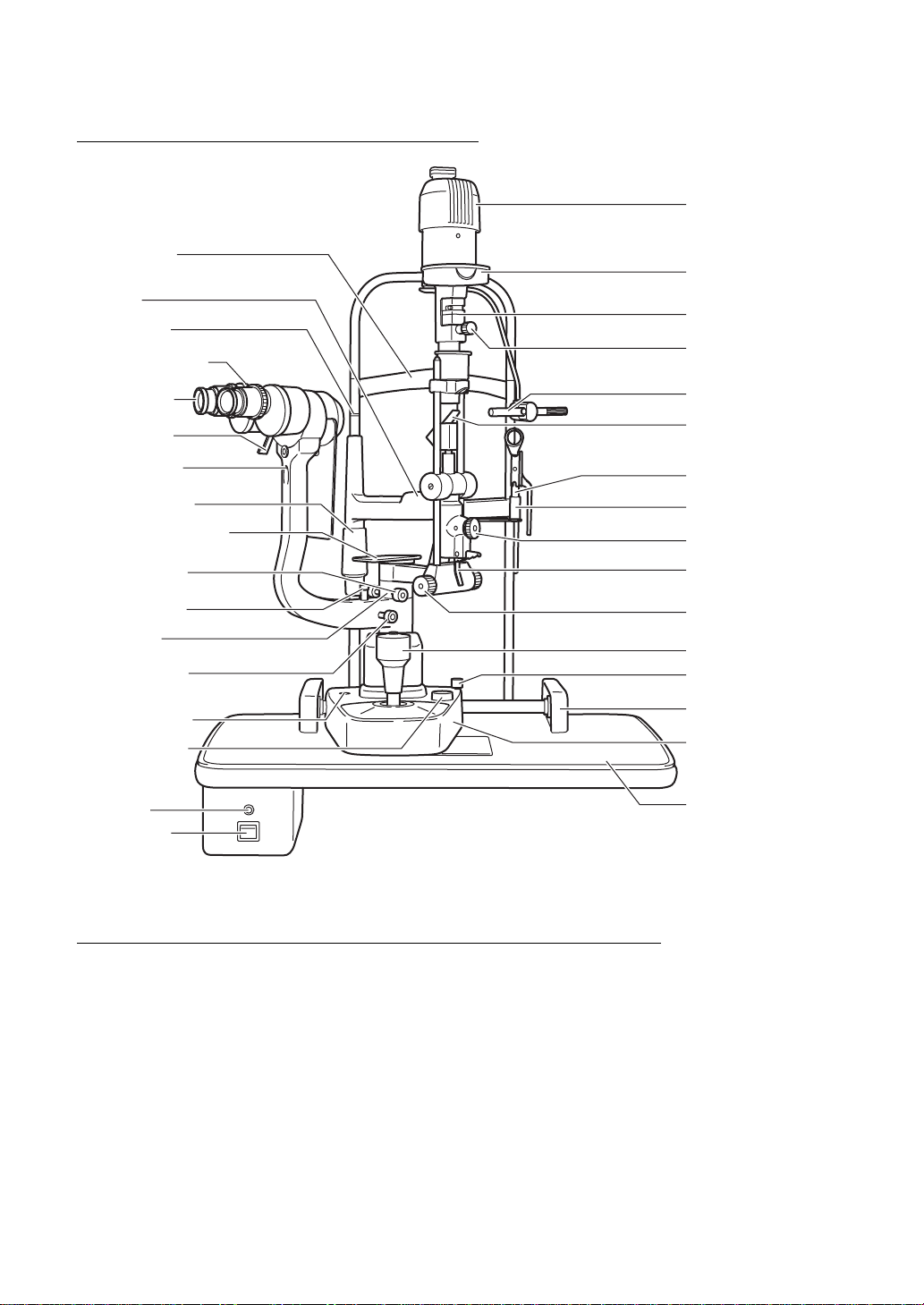
NAMES OF MAIN BODY COMPONENTS .........................................................................7
CONFIGURATION OF PARTS IN CONTACT WITH PATIENT...........................................7
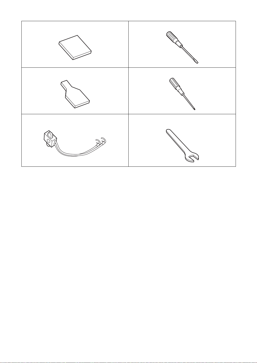
STANDARD ACCESSORIES .............................................................................................8
COMPONENTS.....................................................................................................................10
COMPONENTS................................................................................................................10
ASSEMBLY PROCEDURE ................................................................................................12
ASSEMBLY PROCEDURE...............................................................................................12
CHECKING PROCEDURE...............................................................................................18
OPERATION PROCEDURES ...........................................................................................19
PREPARATION-DIOPTER COMPENSATION AND INTERPUPILLARY
DISTANCE ADJUSTMENT...............................................................................................19
PATIENT POSITION AND FIXATION TARGET................................................................20
BASE OPERATION ..........................................................................................................21
OPERATION OF THE ILLUMINATION UNIT....................................................................22
FUNDUS OBSERVATION WITH THE HRUBY LENS (OPTION).....................................26
TROUBLESHOOTING.........................................................................................................27
TROUBLESHOOTING GUIDE .........................................................................................27
SPECIFICATIONS.................................................................................................................28
ELECTROMAGNETIC COMPATIBILITY..........................................................................30
SYSTEM CLASSIFICATION.............................................................................................34
PURPOSE OF USE..........................................................................................................34
OPERATION PRINCIPLE.................................................................................................34
SHAPE OF PLUG.............................................................................................................35
SYMBOL...........................................................................................................................35
MAINTENANCE.....................................................................................................................36
DAILY CARE.....................................................................................................................36
REPLACING THE BULB...................................................................................................36
REPLACING THE FUSE ..................................................................................................38
REPLACING THE CHINREST PAPER.............................................................................38
ADJUSTMENT OF THE SLIT WIDTH CONTROL KNOB ................................................38
ADJUSTMENT OF THE INCLINATION MOVEMENT ......................................................39
CLEANING........................................................................................................................39
ORDERING SUPPLIES....................................................................................................40
OPTIONAL ACCESSORIES..............................................................................................41
PACHOMETER ATTACHMENT........................................................................................41
10×MEASURING EYEPIECE...........................................................................................41
HRUBY LENS...................................................................................................................42
APPLANATION TONOMETER.........................................................................................42
AUTOMATIC INSTRUMENT TABLE AIT-15.....................................................................42

7
CONFIGURATION
CONFIGURATION
NAMES OF MAIN BODY COMPONENTS
CONFIGURATION OF PARTS IN CONTACT WITH PATIENT
Forehead rest : Polyamide resin
Chinrest : Polyamide resin
Forehead rest
Chinrest
Level marker
Diopter adjustment
ring
10
x
Eyepiece
Magnification
changer lever
Microscope
attaching screw
Chinrest adjuster
Hruby lens guide plate
(Option)
Illumination arm
locking knob
Click-stop roller
Angle scale
Microscope arm
locking knob
Base relay cable
Brightness
adjustment knob
Pilot lamp
Power switch
Lamphouse
Aperture and slit length
display window
Filter selection lever
Aperture and slit
length control knob
Fixation target
Mirror
Hruby lens (Option)
Hruby lens holder
(Option)
Slit centering knob
Illumination
inclination lever
Slit width
control knob
Joystick
Base locking knob
Rail cover
Base
Table

8
CONFIGURATION
STANDARD ACCESSORIES
Make sure that all the following standard accessories are included.
Figures in parentheses are the quantities.
Spare fixation target bulb (1) Focusing test rod (1)
Spare illumination bulb (1) Spare chinrest paper pin (2)
Spare fuse
(Taped onto the rear of the power supply) (3) Brush (1)
Dust cover (1) Instruction manual (1)
Accessory box supplied with Unit Model
Slit Lamp (1) 16× eyepieces (2)
Fixation target (1) Screwdriver (small) (1)
SL-3E

9
CONFIGURATION
Short mirror (1) Screwdriver (large) (1)
Spare long mirror (1) Phillips screwdriver (1)
Spare socket (1) Wrench (not supplied with Unit Model Slit
Lamp) (1)

10
COMPONENTS
COMPONENTS
COMPONENTS
(1) Illumination assembly (2) Chinrest assembly (3) Chinrest paper
(4) Breath shield
(5) Arm hole cover
(6)Instrument type table
(w/power supply) (6)' Unit type table
(w/power supply) (7) Rail cover
(8) Base assembly (9)Microscope (with 10×
magnification eyepieces) (10) Power cable

11
COMPONENTS
Article name Q'ty
(1) Illumination assembly 1
(2) Chinrest assembly 1
(3) Chinrest paper 1
(4) Breath shield 1
(5) Arm hole cover 1
(6) Instrument type table (w/power supply) 1
(6)' Unit type table (w/power supply) 1
(7) Rail cover 2
(8) Base assembly 1
(9) Microscope (with 10× magnification eyepieces) 1
(10) Power cable 1

12
ASSEMBLY PROCEDURE
ASSEMBLY PROCEDURE
ASSEMBLY PROCEDURE
No special tools are required. Included tools are:
• Large screwdriver
• Small screwdriver
• Phillips screwdriver
• Wrench (not supplied with unit model slit lamps)
(1) Mounting the Table
(a) To attach the table on the instrument table AIT-15, use the four 8×24mm bolts with locking
washers.
* Raise the table to allow the bolts to pass through the mounting flange.
* Place the table on the mounting flange of the instrument table and screw the bolts into the
mounting bracket. The controls of the power supply should face the practitioner. Tighten the
bolts securely with the included wrench.
(b) To secure the unit model table to the ophthalmic unit.
* Peel off the tape which secures the plastic washer to the mounting bracket's shaft.
* Insert the shaft of the mounting bracket into the hole of the arm on the ophthalmic unit. The
plastic washer should be between the mounting bracket and the arm.
Note: The power supply is attached to the left side of the unit top (practitioner's view). If the
ophthalmic stand is located to the left of the ophthalmic chair, the power supply must
be relocated to the right side of the unit top to prevent interference with the arm. In this
instance, remove the four wood screws which attach the power supply to the unit top,
re-position the power supply in a similar position to the right side of the unit top, and re-
attach the power supply with the four screws.
Washer

13
ASSEMBLY PROCEDURE
(2) Mounting the Chinrest
* Remove the four screws which are attached to the chinrest mounting plate with the Phillips
screwdriver.
* Place the chinrest cord in the gap between the chinrest mounting plate and the chinrest
assembly. While making sure that the cord is not being pinched by the mounting plate, re-
tighten the previously removed screws.
(3) Mounting the Base Assembly and Rail Covers
* After checking to see that the main unit moves smoothly on the rails, remove the four screws
which are attached to the rails with the screwdriver. Place the rail cover to the rail, and
retighten the previously removed screws.
Chinrest cord
Chinrest mounting plate
Screw
Wheel
Rail

14
ASSEMBLY PROCEDURE
(4) Mounting the Illumination Arm
* Loosen the illumination arm locking knob which is located on the base assembly.
* Turn the brass bearing on the arm support shaft so that the red dot is 30° to 90° from the
shaft index.
* Loosen the set screw in the illumination arm with the small screwdriver.
* Lower the illumination arm carefully into position while lining up the two red dots.
* When the dots are properly aligned, retighten the set screw firmly to properly secure the illu-
mination arm to the shaft of the base assembly.
(5) Mounting the Microscope
* The microscope body has a notched groove and tapped screw-hole in the bottom of the cen-
tral barrel section. While firmly holding the microscope from the top, place the body assem-
bly on the microscope arm matching the notched groove with the stopper on the arm.
* Support the microscope with one hand and tighten the microscope attachment screw
securely onto the body with the large screwdriver.
Note: Avoid touching the front lens of the microscope or the lens surface of the eyepiece.
30° to 90°
Index
Illumination arm locking knob
Index
Set screw
Notched groove
Stopper Microscope arm

15
ASSEMBLY PROCEDURE
(6) Mounting the Breath Shield
* Remove the breath shield attachment screw from the microscope arm.
* Pass the attachment screw through the opening in the breath shield and re-screw it into the
arm.
(7) Removing the Illumination Arm Shipping Pad
* The pad is attached to protect the slit closure mechanism of the illumination arm assembly
during shipping.
* Remove the rubber band and gently pull the pad out.
(8) Connecting Cables
(a) Connect the cable from the top of the chinrest to the lamphouse cover on illumination arm.
* Peel off the tape which secures the lamphouse cover during shipping.
Breath shield attachment screw
Pad
Rubber band
Tape

16
ASSEMBLY PROCEDURE
(b) Connect the chinrest cable, main body cable and power cable to the power supply.
(c) Remove the cable clips from the bottom of the table, slip them over the chinrest and power
cables and re-attach them to the table.
(9) Installing the Chinrest Paper
* Remove the two pins from the chinrest.
* Place the pins through the holes in the chinrest paper. Remove the wrapping from the chin-
rest paper.
* Align the pins with the holes in the chinrest and secure the paper to the assembly.
(10) Spare Parts
* With the table model, an accessory drawer is provided to store the spare parts.
Cable clip

17
ASSEMBLY PROCEDURE
* With the unit model, an accessory box is supplied to store the spare parts.
(11) Mounting the Hruby Lens and Hruby Lens Guide Plate (Option)
Mount the Hruby lens holder and the Hruby lens rail unit onto the chinrest assembly, using
four screws.
* Insert the Hruby lens and Hruby lens holder, which is located on the chinrest assembly.
Do not touch the lens surface.
* Place the guide plate in the hole of the main body's carrier arm. The pointed end should face
the chinrest.
Hruby lens holder
Hruby lens rail
Hruby lens holder
Hruby lens

18
ASSEMBLY PROCEDURE
CHECKING PROCEDURE
(1) Power Plug
* Make sure that the instrument is always properly grounded.
(2) Illumination and Instrument Functions
* Turn the power supply on and observe that the illumination is passing through the opened slit
controls.
* Check to insure that the fixation device is illuminated.
* Check to see that the slit width and length controls, filter lever and magnification changer
lever operate smoothly and properly.
(3) After the installation is completed, turn the power supply off and cover the instrument
with the dust cover.

19
OPERATION PROCEDURES
PREPARATION-DIOPTER COMPENSATION AND INTERPUPILLARY DIS-
TANCE ADJUSTMENT
Before using the instrument, always carry out the diopter compensation and interpupillary distance
adjustments.
(1) Use of the focusing test rod
The focusing test rod, which is a standard accessory, is used to establish the proper micro-
scope settings for each use.
The rod is inserted in the hole, which normally contains the Hruby lens guide plate. Place the
rod in the hole and turn it so that the flat black surface is perpendicular to the microscope's
objective lens.
(2) Preparation of illumination unit
Turn the power switch ON and place the brightness adjustment knob in an intermediate posi-
tion, then set the slit width control knob so that slit is approximately 2 to 3mm wide.
(3) Diopter compensation
To establish the current dioptric setting:
* First, turn the eyepiece ring in a counterclockwise direction until it stops.
* Now, turn the ring in a clockwise direction until a sharp, slit image is seen on the focusing
test rod.
Focusing test rod
Hole of carrier arm
Table of contents
Other Topcon Outdoor Light manuals