TOPMAQ GFW4013 User manual

1
Operator’s Manual
Metal Band Saw
MODEL:GFW4013
CAUTION: Read and follow all Safety Rules
and Operating Instructions before First Use
of this Product. Keep this manual with tools.

2
Technical Specification
Attention: Please choose proper power source, voltage and frequency that are shown in the label for your
metal band saw.
Metal band saw GFW4013
Motor Power 400 W S6 30%
Saw Blade 1435 X 12.7 X 0.65 mm
Saw Blade Teeth 8/12 teeth per inch
Cutting Capacity at Square Material 90
º127 X 125 mm
45 º 76x76mm
Cutting Capacity at circular Material 90
º125 mm
45 º 76mm
Cutting Angle Adjustment 0—60 º
Blade Speed 38-80 m/min
SAFETY
WARNING:To avoid electrical hazards, fire hazards, or damage to the tool, use proper circuit protection.
Use a separate electrical circuit for your tools. To avoid shock or fire, replace power cord immediately if it is worn, cut or
damaged in any way.
GENERAL SAFETY INSTRUCTIONS
WARNING:Read carefully these Operating Instructions. Familiarise with the controls and proper use of the
machine. Keep the Operating Instructions for future reference. The warning labels with instructions attached to
the machine provide important information on safe operation.
1. READ and become familiar with the entire Operator’s Manual. LEARN the tool’s application, limitations and possible
hazards.
2. REMOVE ADJUSTING KEYS AND WRENCHES. Form a habit of checking to see that keys and adjusting wrenches are
removed from the tool before turning ON.
3. KEEP WORK AREA CLEAN. Cluttered areas and benches invite accidents.
4. DON’T USE IN DANGEROUS ENVIRONMENT. Don’t use power tools in damp or wet locations, or expose them to rain.
Keep work area well lighted.
5. KEEP CHILDREN AWAY. All visitors should be kept at a safe distance from work area.
6. MAKE WORKSHOP CHILDPROOF with padlocks.
7. DON’T FORCE THE TOOL. It will do the job better and safer at the rate for which it was designed.
8. USE THE RIGHT TOOL. Do not force tool or attachment to do a job for which it was not designed.
9. USE PROPER EXTENSION CORD. Make sure your extension cord is in good condition. When using an extension cord,
be sure to use one heavy enough to carry the current your product will draw. An undersized cord will result in a drop in
line voltage and in loss of power that will cause the tool to overheat.
10. WEAR PROPER APPAREL. Do not wear loose clothing, gloves, neckties, rings, bracelets, or other jewelry that may get
caught in moving parts. Non-slip footwear is recommended. Wear protective hair covering to contain long hair.
11. ALWAYS WEAR EYE PROTECTION. Wear goggles for protection against projected chips.
12. DISCONNECT TOOLS before servicing; when changing blade and other part.
13. USE RECOMMENDED ACCESSORIES. Consult the Operator’s Manual for recommended accessories. The use of
improper accessories may cause serious injury.

3
14. NEVER STAND ON TOOL. Serious injury could occur if the tool is tipped or if the cutting tool is unintentionally contacted.
15. CHECK FOR DAMAGED PARTS. Before further use of the tool, a guard or other part that is damaged should be
carefully checked to determine that it will operate properly and perform its intended function – check for alignment of
moving parts, binding of moving parts, breakage of parts, mounting, and any other conditions that may affect its operation.
A guard or other part that is damaged should be properly repaired or replaced.
16. NEVER LEAVE TOOL RUNNING UNATTENDED. TURN POWER “OFF”. Don’t leave tool until it comes to a complete
stop.
17. DON’T OVERREACH. Keep proper footing and balance at all times.
18. MAINTAIN TOOLS WITH CARE. Keep tools sharp and clean for best and safest performance. Follow instructions for
lubricating and changing accessories.
19. DO NOT use power tools in the presence of flammable liquids or gases.
20. NEVER REMOVE GUARD, SAFETY DIVICES OR ART OF THE MACHINE.
21. BE CAREFUL. Pay attention to what you are doing. Work reasonably. Do not use the machine when you are tired.
22. HAVE YOUR MACHINE REPAIRED BY AN EXPERT ONLY!This machine meets the applicable safety provisions. Any
repairs may only be executed by an expert, using original spare parts; otherwise, the user could face a risk of injury.
23. Children and persons not familiarised with the machine and persons with limited physical, sensory and mental skills must
not use the machine.
SPECIFIC SAFETY INSTRUCTIONS FOR THE MACHINE
1. Secure the machine to a bench before operating.
2. The machine must be switched off before inserting material to be cut in the vice or before removing material to be cut
from the vice.
3. Keep your hands and fingers in a safe distance from the running saw blade at all times.
4. The saw blade must not be broken by hand.
5. Safety equipment and guards, etc, must not be removed.
6. Never remove the cutting chips by hand. Use a brush at all times.
7. Never leave the machine when in operation.
ELECTRICAL REQUIREMENTS
POWER SUPPLY AND MOTOR SPECIFICATIONS
WARNING: To avoid electrical hazards, fire hazards, or damage to the tool, use proper circuit protection. Use a
separate electrical circuit for your tools. To avoid shock or fire, if power cord is worn or cut, or damaged in any way, have it
replaced immediately.
GROUNDING INSTRUCTIONS
WARNING: This tool must be grounded while in use to protect the operator from electrical shock.
IN THE EVENT OF A MALFUNCTION OR BREAKDOWN, grounding provides a path of least resistance for electric current
and reduces the risk of electric shock. This tool is equipped with an electric cord that has an equipment-grounding conductor
and a grounding plug. The plug MUST be plugged into a matching receptacle that is properly installed and grounded in
accordance with ALL local codes and ordinances.
DO NOT MODIFY THE PLUG PROVIDED. If it will not fit the receptacle, have the proper receptacle installed by a qualified
electrician.
IMPROPER CONNECTION of the equipment-grounding conductor can result in risk of electric shock. The conductor with
green insulation (with or without yellow stripes) is the equipment-grounding conductor. If repair or replacement of the electric
cord or plug is necessary, DO NOT connects the equipment-grounding conductor to a live terminal.
4
CHECK with a qualified electrician or service person if you do not completely understand the grounding instructions, or if you
are not sure the tool is properly grounded.
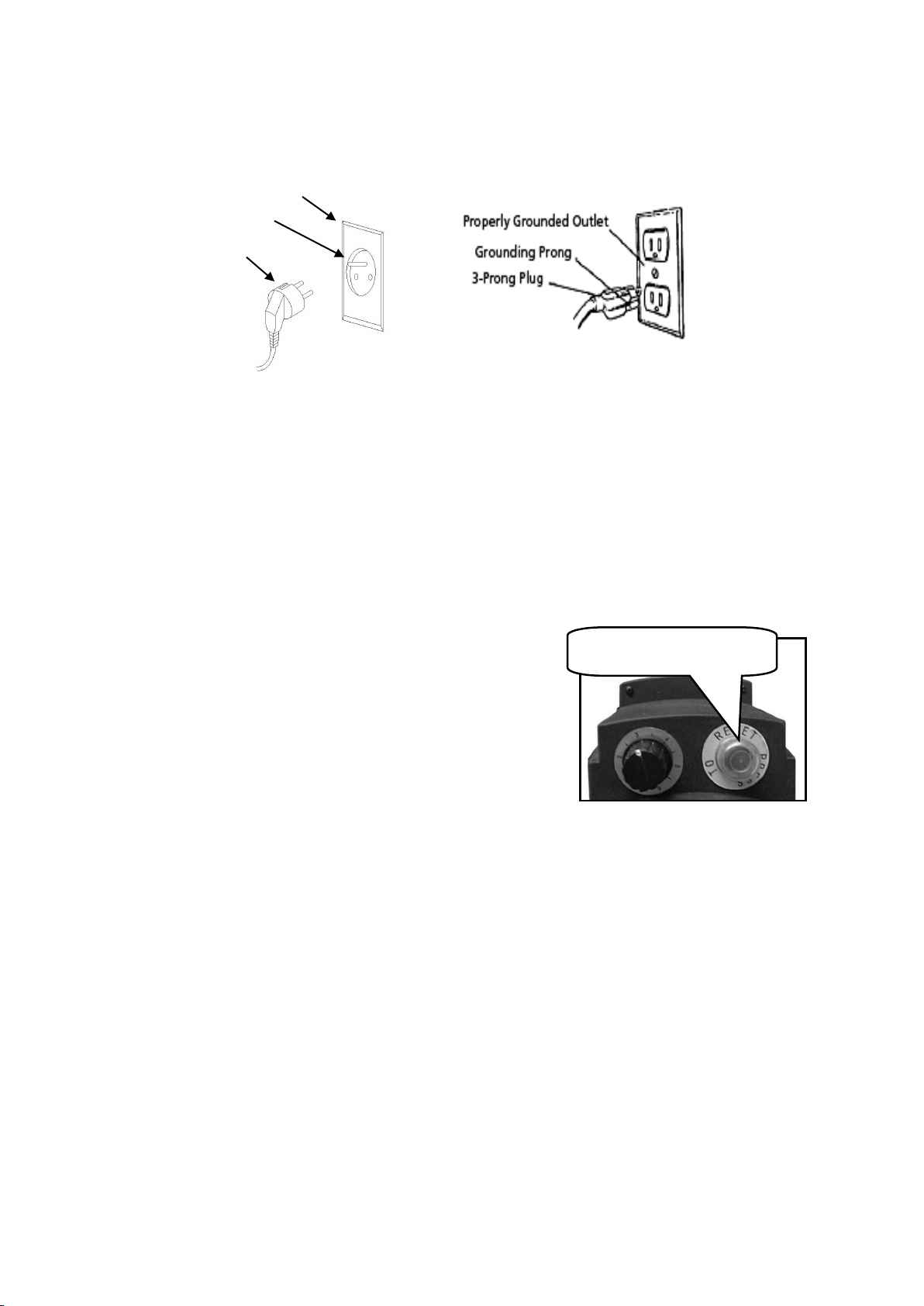
Refer to nether picture:
Properly Ground Outlet
Grounding Prong
3-Prong Plug
WARNING: Improper connection of equipment grounding conductor can result in the risk of electrical shock. Equipment
should be grounded while in use to protect operator from electrical shock.
WARNING: This machine is for indoor use only. Do not expose to rain or use in damp locations.
GUIDELINES FOR EXTENSION CORDS
USE PROPER EXTENSION CORD. Make sure your extension cord is in good condition. When using an extension cord,
be sure to use one heavy enough to carry the current your product will draw. An undersized cord will cause a drop in line
voltage, resulting in loss of power and cause overheating.
Be sure your extension cord is properly wired and in good condition. Always replace a damaged extension cord or have it
repaired by a qualified person before using it. Protect your extension cords from sharp objects, excessive heat and damp or
wet areas.
Attention: There is an overcurrent protection device
in the circuit.
ACCESSORIES AND ATTACHMENTS
RECOMMENDED ACCESSORIES
WARNING: To avoid injury:
• Use only accessories recommended for machine.
• Follow instructions that accompany accessories. Use of improper accessories may cause hazards.
• Use only accessories designed for this machine to avoid injury from thrown broken parts or work pieces.
• Do not use any accessory unless you have completely read the instruction or operator’s manual for that
accessory.
Overcurrent protection
5
CARTON CONTENTS
UNPACKING AND CHECKING CONTENTS
Carefully unpack the machine and all its parts, and compare against the illustration following.
WARNING:
• To avoid injury from unexpected starting, do not plug the power cord into a power source receptacle during unpacking and
assembly. This cord must remain unplugged whenever you are assembling or adjusting the machine.
• If any part is missing or damaged, do not plug machine in until the missing or damaged part is replaced, and assembly is
complete.
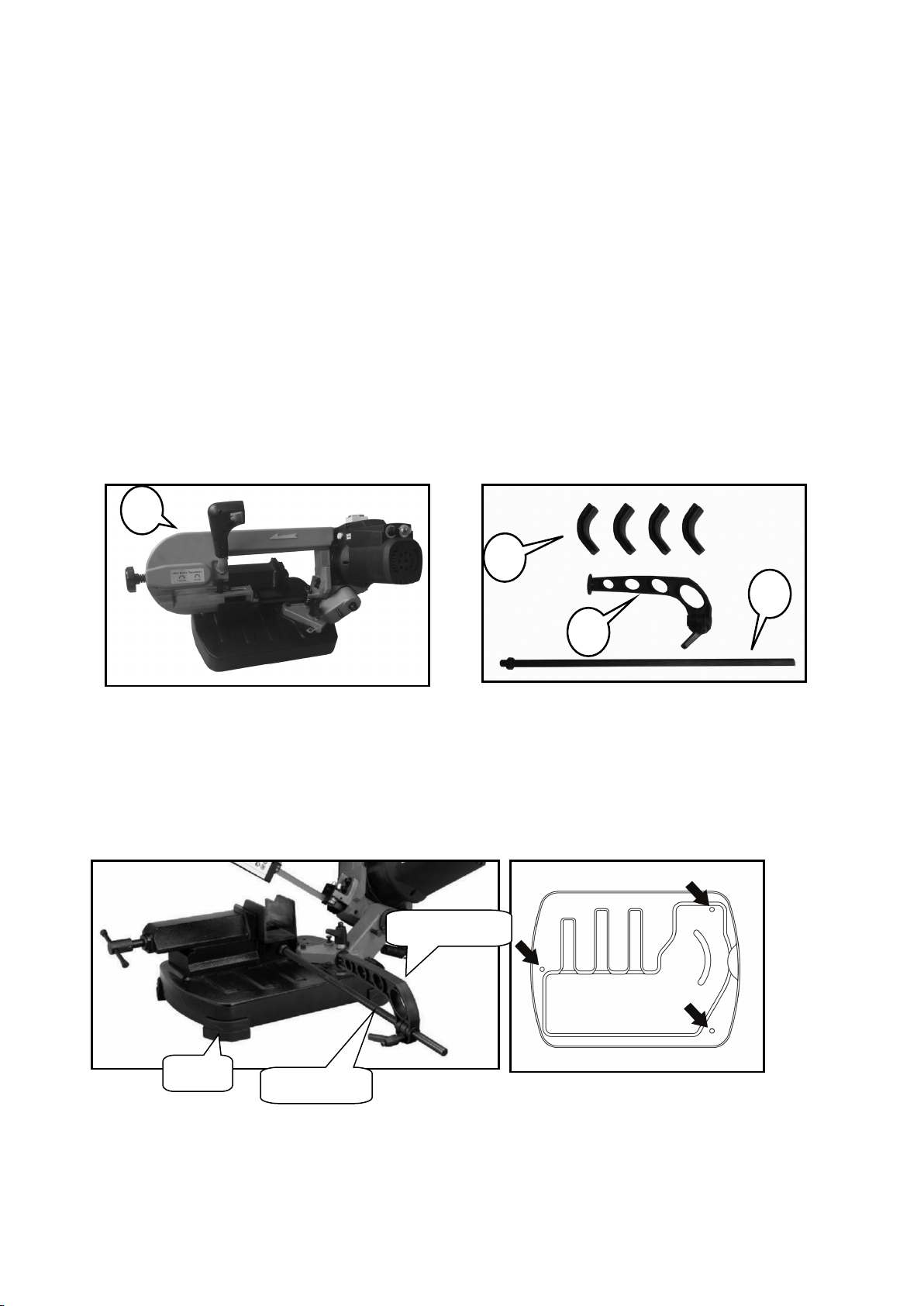
TABLE OF LOOSE PARTS
Unpack carton; check you machine to see parts listed below:
1. Metal band saw X1
2. Foot X4
3. Work stop with lock handle X1
4. Guide rail with hex nut X1
ASSEMBLY AND INSTALLATION
1. Attach four feet to base.
2. Place the machine on a work bench, secure it by using 3 holes provided on the base.
3. Screw the guide rail to the thread hole on vise base. Tighten the nut to fix it,
4. Attach the work stop to the guide rail, secure it by tightening the lock handle
1
2
3
4
Foot
Guide rail
Work stop

6
ADJUSTMENTS
1. Positioning the work stop
Use the work stop supplied if you have to do several cuts on
pieces of the same length.
Loosen the lock handle A,place the work stop at the desired
distance from the blade.
Tighten the lock handle Aagain.
CAUTION! Make sure that the length stop does not
interfere with the downward movement of the blade.
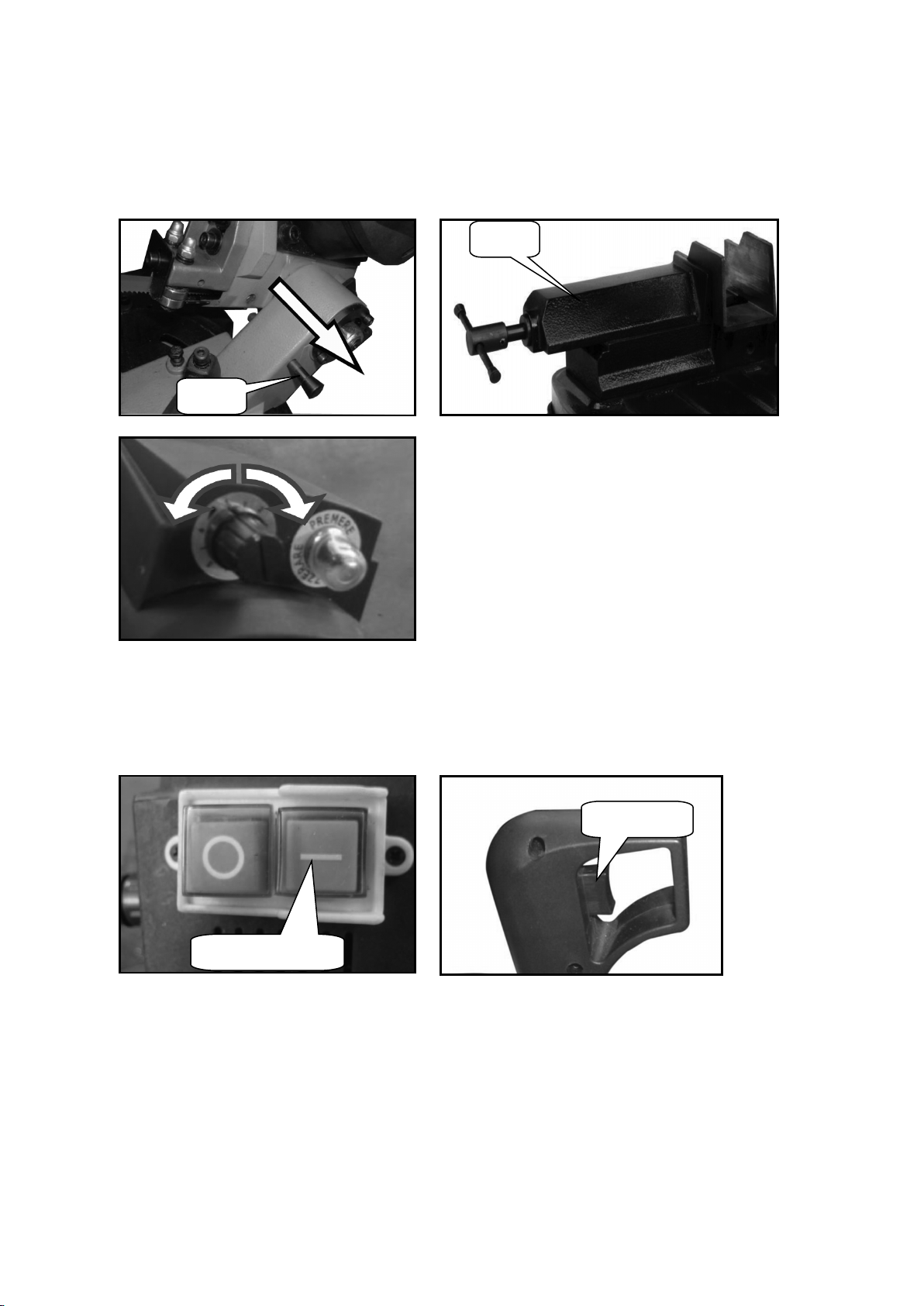
2. Cutting angle adjustment
The band saw can cut at an angle varying from 0º
to 60º.
Loosen the lock handle B, turn the swivel support
until the mark on support matches desired angle
on the scale. Then lock the swivel support again
CAUTION! Make sure the lock handle B has
been tightened before turning on the machine.
3. Sliding blade guide
The sliding blade guide must be adjusted before
cutting a different workpiece. If the adjustment is
not done, it would result in an unclean cut.
Loosen the lock handle C, Slide the blade guide to
move it closer to the workpiece then retighten the
lock handle C.
4. Cutting speed
The cutting speed always depends on the material being
cut.
To select the most suitable speed, turn the control knob Dto
increase or decrease the speed as you require.
Example:
Common steel: 40-60m/min
Aluminum, alloy; 80m/min
Pipes/sections: 70-80m/min
A
B
Swivel support
CC
D
7
OPERATION
1. Pull out the pin from the hole in the body and tilt the saw body to upper position.
Use the vice clamping the workpiece,
Adjust the cutting speed.
2. Push the green button to turn on the main switch, using the index finger of your right hand, press the
run button.
Gradually lower the machine body until it comes lightly into contact with the workpiece.
Now begin to apply gradual pressure on the workpiece and complete the cut.
Pin
Vice
Push to turn on
Run button

8
MAINTENANCE
Warning: Turn off the machine and disconnect from the power supply before conducting maintenance
work or settings.
Change the saw blade
Caution! Always wear protective gauntlets before changing saw blade.
Remove the protective casing unscrewing the six screw
Loosen the blade tension, turning the knob E in the anti-clockwise direction.
Extract the blade first from the guides and then from the cast iron pulleys, check to make sure the
blade teeth are facing toward the work piece.
Insert the new blade first between the guides and then into the cast iron pulleys.
Turn the knob E, adjust the blade tension.
Replace the protective casing.
Reposition the blade guides in the correct position for next cut.
Machine care
Usually check the condition of the power supply cords and replace them if they are broken, or even
worse if the internal wires are shown.
Use a brush and a shop vacuum to remove chips and other debris from the machine.
Always keep the machine handgrip clean to prevent accidental slipping during use.
Remove the processing residues from the cutting area and the blade guides whenever necessary.
If you do not intend to use the sawing machine for a long time, clean it and put it in a dry place if
possible. In these cases it is advisable to slacken off the blade so that it is not kept for any reason.
To ensure effective machine operation, check the condition of the blade daily and sharpen it
whenever necessary.
E

9
TROUBLESHOOTHING
PROBLEM
CAUSE
SOLUTION
The motor does not work Defective motor, power cable or
plug
The overload cutout has tripped
Specialized personnel should
check the machine
Reset the overload cutout.
Overload cutout tripped Motor overload caused by
excessive cutting pressure
Motor breakdown
Perform the cut on the piece at
the correct pressure
Specialized personnel should
check the machine
Inaccurate cut squaring Excessive cutting pressure
Incorrect blade tooth in relation to
the workpiece
Incorrect adjustment of the
sliding blade guide
Incorrect cutting speed in relation
to work piece
The workpiece is wrongly
positioned in the vice
Poor blade tension.
Decrease cutting pressure
Chose proper blade for
workpiece
Check blade guide adjustment
Adjust to correct cutting speed
Check workpiece positioning
and clamping in the vice
Check blade tension
The blade tends to protrude
from the guide
Excessive blade tension
Incorrect eccentric blade guide
adjustment
The blade slips on the pulleys,
caused by oil or grease required
for cutting operations
Check blade tension
Check eccentric blade guide
adjustment
Never use any type of lubricant
or coolant for the cutting
operations; specialized personnel
should check and replace the
pulleys, if necessary,

10
ASSEMBLY DIAGRAM
Table of contents
Other TOPMAQ Saw manuals


