manuals.online logo
Brands
  1. Home
  2. •
  3. Brands
  4. •
  5. Bouyer
  6. •
  7. Amplifier
  8. •
  9. Bouyer AP-104 User manual

Bouyer AP-104 User manual

AP-104
Préamplificateur
Preamplifier
Code : 596247
Date : 04/2015
Version : 2
1
BOUYER INDUSTRIE
1270, avenue de Toulouse Tél : +33 (0)5 63 21 30 00 [email protected]
82000 Montauban –France Fax : +33 (0)5 63 03 08 26 www.bouyer.com
I –DESCRIPTION
La platine AP-104 est un préamplificateur
pour montage encastré ou en saillie sur une
paroi (Fig. I et II). Elle comporte 4 entrées (2
MIC -2 AUX) en façade et une sortie ligne 0 dB
sur bornier. Plusieurs platines peuvent être
montées en cascade sur une seule ligne
audio. La mise en service est obtenue par un
interrupteur à clé. Une alimentation
extérieure est à prévoir.
I –DESCRIPTION
The AP-104 is preamplifier to be surface or
flush mounted to a wall (Fig. I et II).
It offers 4 inputs (2 MIC –2 AUX) and a 0 dB
output on terminal. Several panels may be part
in parallel on a single audio line. A key allows to
switch on the panel.
It is necessary to have an external power
supplier.
II –CARACTERISTIQUES TECHNIQUES
Alimentation ..……………..….…24 VDC –50 mA
Interrupteur à clé 3 positions
Position 1 : OFF
Position 2 : ON entrée MIC et AUX mélangées
Position 3 : ON entrée MIC prioritaire sur AUX
Chaque platine est livrée avec 2 clés. Les clés sont
identiques pour toutes les platines.
Entrées Microphone ………………...symétriques
Micro électrodynamique ou électret –Prise XLR
Sensibilité ………………………….……………..………….-55 dB
Bande passante (3 dB) ……..……………..55 Hz à 16 kHz
Entrées Auxiliaire …………………...asymétriques
Prise CINCH double
Sensibilité ………………………….……………..………….-10 dB
Bande passante (3 dB) ……..………….….20 Hz à 22 kHz
Entrée Cascadable ……………..……..asymétrique
Sur bornier interne
Niveau nominal ………………………….………….……….0 dB
Sortie ligne ….…..symétrique (transformateur)
Sur bornier interne
Niveau nominal ………………………….………….……….0 dB
Priorité MIC / AUX
Par détection de modulation
Réglage par le bouton « Detect » en façade
Prérégler le taux d’atténuation par PT5
Réglage de –6 dB à atténuation totale
Sortie télécommande
Télécommande (0 V actif) soit à la mise en service
soit par détection de modulation microphone.
Sélection par cavalier interne (SW1)
Dimensions ……………………..145 x 145 x 45 mm
Poids …………………………………………….………..1 kg
II –TECHNICAL SPECIFICATIONS
Power supply ...……………..…..…24 VDC – 50 mA
Switch on key with 3 positions
Position 1 : OFF
Position 2 : ON MIC and AUX inputs are mixed
Position 3 : ON MIC inputs have priority over AUX
inputs. Each panel is provided with 2 keys.
The keys are identical to every panel.
Mic input …………………………………….......balanced
For electret and dynamic microphone, XLR socket
Sensitivity ………………………….………………….……….-55 dB
Bandwith (3 dB) …………………….…..…….55 Hz to 16 kHz
Aux input ……….……………………….…...unbalanced
RCA Dual CINCH sockets
Sensitivity ………………………………..….……..………….-10 dB
Bandwidth (3 dB) ……..…………..………...20 Hz to 22 kHz
Parallel input …………………………...…..unbalanced
Input on internal terminal
Nominal level …………………………...………….………..….0 dB
Line output…………..…..balanced on transformer
Ouput on internal terminal
Nominal level …………………………...………….………..….0 dB
MIC / AUX priority
By detection of modulation
Set up by using ‘Detect’ button
Muting level is achieved by using PT5
Adjustment of –6 dB to total mutting
Remote control output
Remote control (0 V active) either by switching or by
modulation detection of the MIC selection is mode
by using jumper (SW1)
Dimensions ………..……………..145 x 145 x 45 mm
Poids ………………………………………...……………..1 kg
Ce document n’est pas contractuel ; toute modification pouvant intervenir sans préavis / This document is not legally binding, we reserve the right to modify descriptions and specifications without notice.
Fig. I
Encastré / Surface
Fig. II
Saillie / Flush mounted
AP-104
Préamplificateur
Preamplifier
Code : 596247
Date : 04/2015
Version : 2
2
BOUYER INDUSTRIE
1270, avenue de Toulouse Tél : +33 (0)5 63 21 30 00 [email protected]
82000 Montauban –France Fax : +33 (0)5 63 03 08 26 www.bouyer.com
III –PRESENTATION
① Façade
② 4 fis de fixation façade
③ Interrupteur à clé de mise en service
④ Voyant allumé à la mise en service
⑤ Bouton de volume MICRO
⑥ Bouton de volume AUX
⑦ Prises XLR d’entrée MICRO
⑧ Prises CINCH d’entrée AUX
⑨ Bouton de sensibilité détection
III –PRESENTATION
① Panel
② 4 screws to fixe the panel
③ Key to switch ON
④ ON / OFF LED
⑤ MIC volume button
⑥ AUX volum button
⑦ XLR socket MIC inputs
⑧ RCA socket AUX inputs
⑨ Sensitivity button
IV–INSTALLATION
Câbler la platine avec du fil blindé.
Relier le blindage : à la masse du préamplificateur (socle de la
prise DIN ou XLR), et à la masse de l’AP-104 (Fig. IV).
Les sorties S0 et S1 attaquent l’entrée symétrique (1 et 3 DIN ou
3 et 2 XLR). 0 et + reliés à une alimentation 24 V, 50 mA par
nombre de platine.
Sortie télécommande « T » :
permet d’utiliser une carte de priorité AZ-1229 ou AZ-
1239. Dans ce cas relier « T » en 4 de la prise DIN, à
l’entrée du préamplificateur.
Télécommande activée soit à la mise en service par clé
(SW1 sur ON) soit par la détection de modulation
MICRO (SW1 sur MIC).
Si la sortie « T » est utilisée par une commande annexe, voyant
ou relais, utiliser le « 0 V ». Dans le cas d’un relais, prévoir une
diode 1A câblée en inverse sur la bobine du relais. La sortie « T »
est à collecteur ouvert 200 mA max, 30 V max.
Pour l’installation de plusieurs platines :
Alimentation 24 V et télécommandes câblées en bus
Sorties signal audio S0 et S1 cascadées
Le potentiomètre ajustable PT5 permet de régler le taux
d’atténuation des entrées musique (CINCH) lorsqu’une entrée
micro détecte une modulation réglable de -6 dB à atténuation
totale.
IV–INSTALLATION
Use screened cable to wire the panel.
Link the screen to the eath of preamplifier (Base of DIN or XLR
plug) and to the earth of AP-104 (Fig. IV). Outputs S0-S1 are
linked to balanced input (pin 1 + pin 3 DIN or pin 3 + pin 2 XLR).
0 and + are linked to 24 V –50 mA power supply.
Remote control output « T » :
Allows to use a priority module AZ-1229 or AZ-1239.
In this case link « T » to pin 4 of DIN plug of
preamplifier.
Remote activated either when the panel is switched
ON by using the key (SW1 on ON position) or by
modulation detection of the MIC (SW1 on MIC
position).
In case output « T » is used by an other external unit, led or
relay, use « 0 V ». In case of a relay, use 1A diode opposite
cabled on the trip coil. Output « T » is open collector 200 mA
max –30 V max.
Several panels used :
24 V power supply and the remote controls are wired
in bus
Audio output signal S0 –S1 are in parallel
Potentiometer PT5 allows to set the mute level of the music
inputs (RCA) from –6dB to total when a MIC input detects a
modulation.
Fig. III
Fig. IV
AP-104
Préamplificateur
Preamplifier
Code : 596247
Date : 04/2015
Version : 2
3
BOUYER INDUSTRIE
1270, avenue de Toulouse Tél : +33 (0)5 63 21 30 00 [email protected]
82000 Montauban –France Fax : +33 (0)5 63 03 08 26 www.bouyer.com
IV - UTILISATION
Connecter le (ou les) microphone(s) sur les prises XLR ⑦.
Connecter des sources musiques, lecteur cassette ou CD sur
les prises CINCH ⑧ (Fig. III).
Les 2 sorties d’une source stéréo seront mélangées en mono.
Tourner la clé sur ON-MIC pour obtenir un fonctionnement
des entrées micro et musique en mélange.
Tourner la clé sur ON-PRIO pour obtenir un fonctionnement
prioritaire des entrées micro sur les entrées AUX. Dans ce cas,
le bouton « Detect », règle la sensibilité de détection micro.
IV - USE
Connect he mic(s) to XLR sockets ⑦.
Connect the music sources, to the RCA sockets ⑧ (Fig. III).
The 2 outputs of a stereo sources are mixed to a mono signal.
Turn the key to ON-MIC position, to obtain a mixing of mic and
music sources.
Turne the key to ON-PRIO position to obtain a priority of the
mic inputs over the music sources. In this case « Detect »
button allow to se the sensitivity of mic detection.
V - MAINTENANCE
En cas de panne :
Vérifier la présence de l’alimentation 24 V sur le
bornier
Contrôler le câblage (Fig. IV)
Retourner l’appareil à BOUYER ou faire appel à un
dépanneur professionnel
V - MAINTENANCE
In case of failure :
Check the 24 V power supply on the terminal
Control the wiring and connections (Fig. IV)
Otherwise the product has to be sent back to the
factory or repaired by a recognised dealer
VI - RECOMMANDATION
En fin de vie du produit, s’il est installé sur le
territoire français (DOM-TOM inclus), veuillez
contacter BOUYER pour organiser sa
destruction conformément à la directive DEEE.
Dans le cas contraire, veuillez appliquer la
règlementation locale du pays d’installation du
produit.
VI - RECOMMENDATION
This product is subject to European regulation
2002/96/CE (also called W.E.E.E).
Please contact your local dealer for destruction
in end of life.

Other Bouyer Amplifier manuals

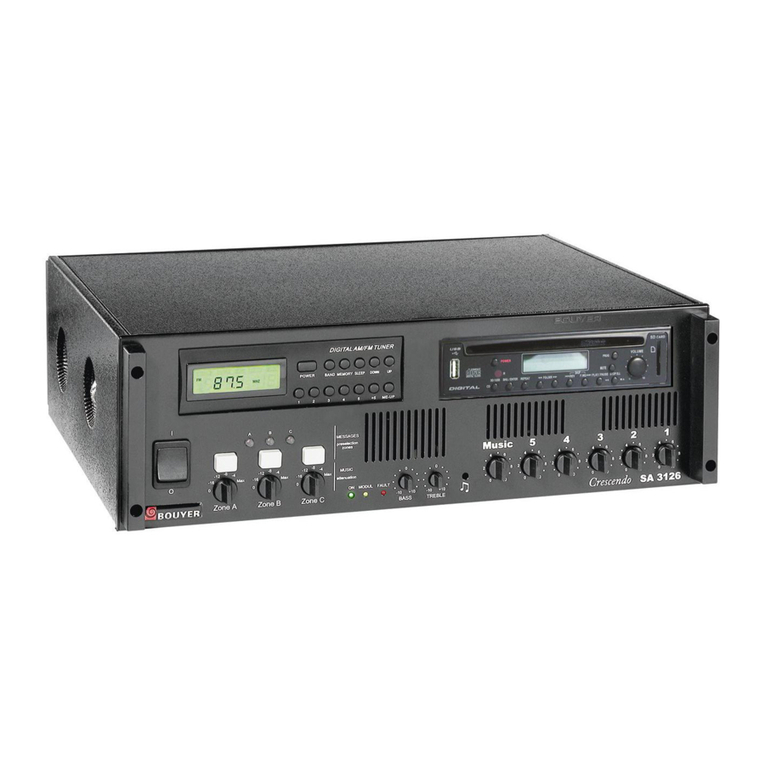
Bouyer SA-3126 Series User manual

Bouyer

Bouyer SA-3126 Series User manual

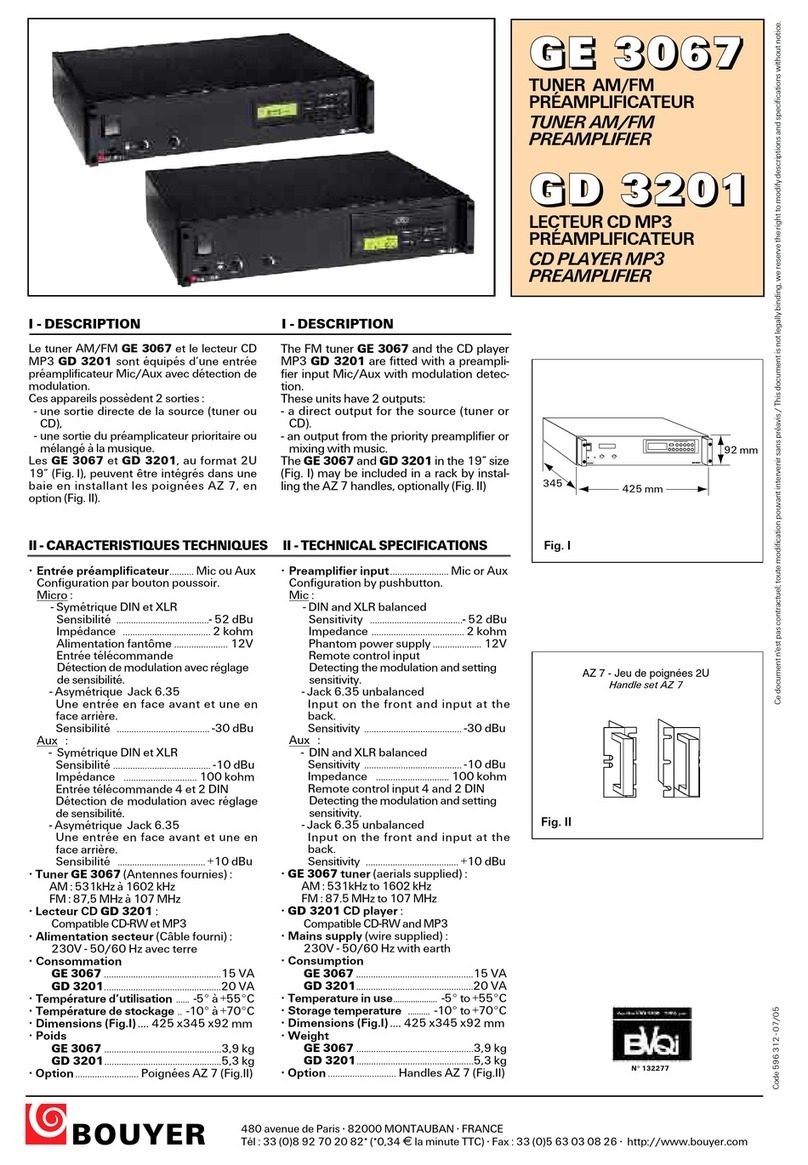
Bouyer GE 3067 User manual

Bouyer

Bouyer GE 3067 User manual

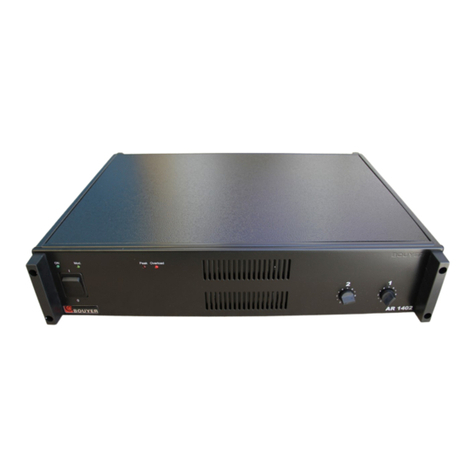
Bouyer AR 1402 User manual

Bouyer

Bouyer AR 1402 User manual

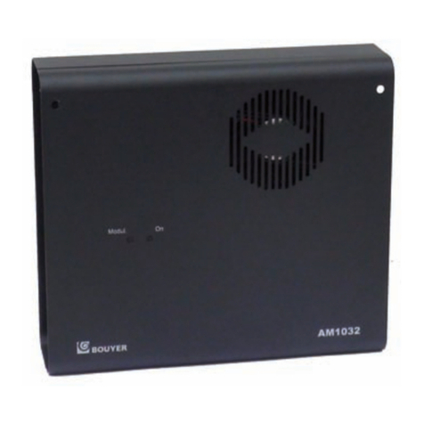
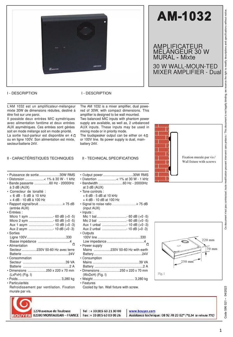
Bouyer AM 1032 I User manual

Bouyer

Bouyer AM 1032 I User manual

Bouyer AS-4000 Series User manual

Bouyer

Bouyer AS-4000 Series User manual

Bouyer EXCELLENCE PR 1406 User manual

Bouyer

Bouyer EXCELLENCE PR 1406 User manual

Bouyer AD1-1075 User manual

Bouyer

Bouyer AD1-1075 User manual

Bouyer AR 1050 User manual

Bouyer

Bouyer AR 1050 User manual

Bouyer IL 100 User manual

Bouyer

Bouyer IL 100 User manual

Bouyer AM-2015 User manual

Bouyer

Bouyer AM-2015 User manual

Bouyer AM-2015-PACK User manual

Bouyer

Bouyer AM-2015-PACK User manual

Bouyer EB 134 User manual

Bouyer

Bouyer EB 134 User manual

Bouyer SA 3126 User manual

Bouyer

Bouyer SA 3126 User manual

Bouyer GE 3267 User manual

Bouyer

Bouyer GE 3267 User manual

Bouyer EXCELLENCE Series User manual

Bouyer

Bouyer EXCELLENCE Series User manual

Bouyer SA-1127 User manual

Bouyer

Bouyer SA-1127 User manual

Bouyer AP 3804 User manual

Bouyer

Bouyer AP 3804 User manual

Bouyer AS 3066 User manual

Bouyer

Bouyer AS 3066 User manual

Bouyer Crescendo SA 3126 Instruction manual

Bouyer

Bouyer Crescendo SA 3126 Instruction manual

Bouyer AM-1032 User manual

Bouyer

Bouyer AM-1032 User manual

Popular Amplifier manuals by other brands

BRAX X 2000.2 GRAPHIC EDITIONS instruction manual

BRAX

BRAX X 2000.2 GRAPHIC EDITIONS instruction manual

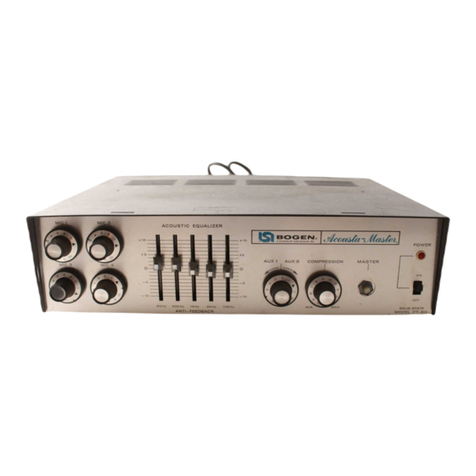
Lear Siegler BOGEN Acousta-Master CT Series manual

Lear Siegler

Lear Siegler BOGEN Acousta-Master CT Series manual

Bugera 1960 Infinium quick start guide

Bugera

Bugera 1960 Infinium quick start guide

Crown 280MA Specifications

Crown

Crown 280MA Specifications

Fender AMP CAN Reference and owner's manual

Fender

Fender AMP CAN Reference and owner's manual

BST PRO UPA-120 USB instruction manual

BST

BST PRO UPA-120 USB instruction manual

Tholin-Audio PR-1 User manual and warranty

Tholin-Audio

Tholin-Audio PR-1 User manual and warranty

Onkyo Integra P-388F Service manual

Onkyo

Onkyo Integra P-388F Service manual

iSP HDA 1003 owner's manual

iSP

iSP HDA 1003 owner's manual

Pioneer GM-X922/X1R/UC Service manual

Pioneer

Pioneer GM-X922/X1R/UC Service manual

Inter-m PA-9336 operating manual

Inter-m

Inter-m PA-9336 operating manual

Williams Sound Pocketalker 2.0 PKT E1 user manual

Williams Sound

Williams Sound Pocketalker 2.0 PKT E1 user manual

Yamaha MLA8 Specifications

Yamaha

Yamaha MLA8 Specifications

Opus LD Series Installation and user manual

Opus

Opus LD Series Installation and user manual

Pioneer C-21 operating instructions

Pioneer

Pioneer C-21 operating instructions

Martin Audio ICT500 user guide

Martin Audio

Martin Audio ICT500 user guide

Nuvo Essentia BTicino NV-E6DS-BT installation manual

Nuvo

Nuvo Essentia BTicino NV-E6DS-BT installation manual

Marantz MM-9000 Service manual

Marantz

Marantz MM-9000 Service manual

manuals.online logo
manuals.online logoBrands
  • About & Mission
  • Contact us
  • Privacy Policy
  • Terms and Conditions

Copyright 2025 Manuals.Online. All Rights Reserved.