TorcUP EMINI User manual

1
OPERATION AND MAINTENANCE
MANUAL
Torque Wrench Power Pump
MODELS: EMINI-115V, EMINI-230V
EMINI
1025 Conroy Place, Easton PA 18040 * U.S.A.
Phone: +1 610-250-5800 * Fax:+1 610-250-2700
Toll Free: 1-888-TORCUP-1

TorcUP Inc. is not responsible for customer modification of tools for applications on
which TorcUP Inc. was not consulted.
TorcUP has taken every care in preparing this Operational Manual that is intended as a technical guideline only. TorcUP
accepts no liability in relation to any use or reliance made of any information in this Operational Manual. All information,
illustrations and specifications in this Operational Manual are based on the latest information available at the time of
publica-tion. The right is reserved to make changes at any time without notice. Equipment operators and installers shall be
respon-sible for ensuring that a safe working environment and safe systems of work are in place before operating the
equipment.
2
IMPORTANT SAFETY INFORMATION ENCLOSED.
READ THIS MANUAL BEFORE OPERATING PUMP.
IT IS THE RESPONSIBILITY OF THE EMPLOYER TO PLACE THE INFORMATION IN THIS
MANUAL INTO THE HANDS OF THE OPERATOR.
FAILURE TO OBSERVE THE FOLLOWING WARNINGS COULD RESULT IN INJURY.
The use of other than genuine TorcUP replacement parts may result in safety
hazards, decreased tool performance, and increased maintenance, and may
invalidate all warranties. Repairs should be made only by authorized
personnel. Consult your nearest TorcUP Authorized Service Center.
Refer All Communications to the Nearest TorcUP Ofce or Distributor.
For Technical Support & Information Contact:
TorcUP Inc.
1025 Conroy Place, Easton, PA 18040 USA
Phone: +1 610-250-5800 Fax:+1 610-250-2700
email: [email protected]
CONTENTS
Operational and Maintenance Manual for
TorcUP EMINI-115V & EMINI-230V
Version 3: 2023OCTOBER
Category Page # Category Page #
Manual Index 2
General Warnings 3
Pressure Torque Setting 10
Safe and Correct Use 4-6
Completing the job
10
Warranty Statement 5
Periodic Maintenance
10
Working Pressure 5
Oil Level 6,11
Adding Oil 6
Oil Intake Screen 11
General Safety 6
Oil Flushing 11
Technical Speci ications 7
Troubleshooting 12
Electrical 8
EMINI Parts Index 13-29
Connecting Tools 8
Pendant 9,23
Initial Startup 8
Electrical Connection 27
Control Valves 9 4-Port Manifold 29
Power Control Switches 9
Hydraulic Connection 28
Notes 30

3
FAILURE TO OBSERVE THE FOLLOWING WARNINGS COULD RESULT IN INJURY
Do NOT exceed Maximum Pressure. See Torque Chart with Tool. Damage May Occur.
Always wear eye
protection
when
operating or
performing
maintenance
on this tool.
Always wear ear protection
when operating this tool. Do not carry
the tool
by the hose.
Keep body stance
balanced and rm.
Do not overreach
when operating this
tool.
USING THE TOOL
• Keep hands, loose clothing & long hair away from the reaction arm and working area during operation.
• This tool will exert a strong reaction force. Use proper mechanical support and correct reaction arm
positioning to control these forces. Do not position the reaction arm so that it tilts the tool o the axis of
the bolt and never use the swivel inlets as a reaction stop.
• Avoid sharp bends and kinks that will cause severe back-up pressure in hoses an lead to premature
hose failure.
• Use accessories recommended by TorcUP.
• Use only impact sockets and accessories. Do not use hand (chrome) sockets or accessories.
• Use only sockets and accessories that correctly t the bolt or nut and function without tilting the tool o
the axis of the bolt.
• This tool is not insulated against electric shock.
• This equipment must not be operated or serviced unless the operator read the operating instructions
and fully understands the purpose, consequences and procedure of each step.
Depending on the working environment your local health and safety regulations may require
you use protective gear (i.e. Ear Protection, Safety Shoes, Hard Hat, Gloves, Coveralls, etc.).
In case external forces are exerted on the equipment, non-compliance with these regulations
may result in injury. EAR PROTECTION MUST BE WORN WHEN OPERATING THIS TOOL.
The Torque Reaction Arm must be
positioned against a positive stop.
Do not use the arm as a dead
handle. Take all precautions to
make certain the operator’s hand
cannot be pinched between the
arm and a solid object.
Do not use damaged,
frayed or deteriorated
hydraulic hoses
and ttings.

4
SAFE AND CORRECT USE
Operation of the Equipment in Accordance with Specied Use
1. Inspect, maintain, operate and install the tool in accordance with all applicable standards and
regulations (local, state, country, federal, etc.)
2. Do not remove any labels. Replace any damaged labels immediately.
3. Be sure all hoses and ttings are the correct size and tightly secured.
4. Do not use damaged, frayed or deteriorated hydraulic hoses and ttings. Do not paint hoses.
5. Do not lubricate tools with ammable or volatile liquids such as kerosene, diesel or jet fuel. Use
only TorcUP recommended lubricants.
6. Use only proper cleaning solvents to clean parts. Use only cleaning solvents which meet current
safety and health standards. Use cleaning solvents in a well ventilated area.
7. Keep work area clean, uncluttered, ventilated and illuminated.
Safety Information When Using The Tool
1. When wearing gloves, always be sure that the gloves will not prevent the throttle mechanism
from being released.
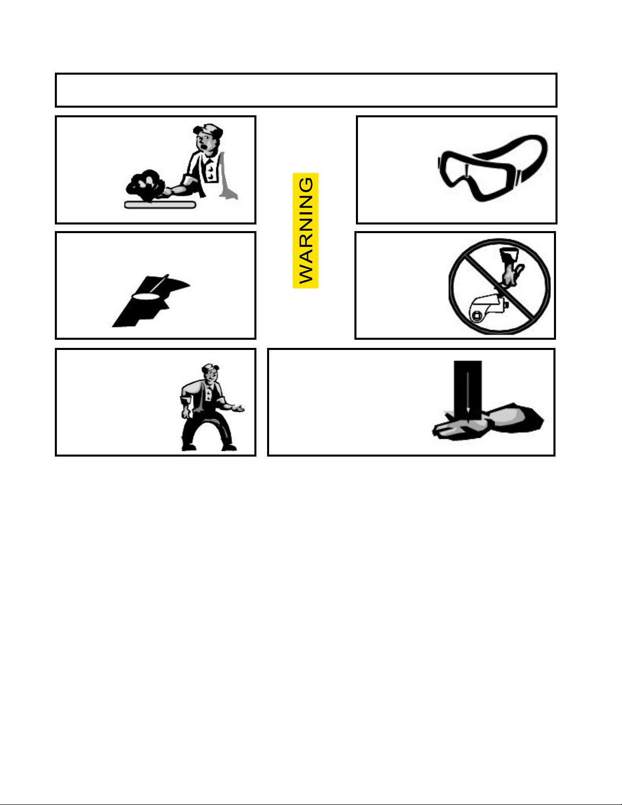
2. Always wear eye protection when operating or performing maintenance on this tool.
3. Always wear hearing protection when operating this tool.
4. Always use personal protective equipment appropriate to the tool used and material worked.
This may include dust mask or other breathing apparatus, safety glasses, ear plugs, gloves,
apron, safety shoes, hard hat and other equipment.
5. Keep others a safe distance from your work area, or ensure they use appropriate personal
protective equipment.
6. Be aware of buried, hidden or other hazards in your work environment. Do not contact or dam-
age cords, conduits, pipes, or hoses that may contain electrical wires, explosive gases or harmful
liquids.
7. Keep hands, loose clothing, long hair and jewelry away from working end of tool.
8. Power tools can vibrate in use. Vibration, repetitive motions or uncomfortable positions may be
harmful to your hands and arms. Stop using any tool if discomfort, tingling feeling or pain occurs.
Seek medical advice before resuming.
9. Keep body stand balanced and rm. Do not overreach when operating this tool. Anticipate and
be alert for sudden changes in motion, reaction torques, or forces during start up and operation.
10. DO NOT USE THIS TOOL WHEN TIRED, UNDER THE INFLUENCE OF MEDICATION,
DRUGS OR ALCOHOL.
11. Never use a damaged or malfunctioning tool or accessory.
12. Do not modify the tools, safety devices or accessories.
13. Do not use this tool for purposes other than those recommended
14. Never exceed rated pressure of tool.

5
SAFE AND CORRECT USE
IMPORTANT - READ CAREFULLY
This manual contains important information for the correct installation, operation and maintenance of
this equipment. All persons involved in the installation, operation and maintenance of this equipment
must be thoroughly familiar with the contents of this manual. To safeguard against the possibility
of personal injury or property damage, follow the recommendations and instructions of this manual.
Keep this manual for reference.
WARRANTY STATEMENT
TorcUP products are warranted to be free of defects in materials and workmanship under normal use
for as long as the original purchaser owns them, subject to the guidelines and limitations listed. This
warranty does not cover: normal wear & tear, cosmetic items, abuse, overloading, alterations, im-
proper uid, or use in a manner for which they are not intended. If the customer believes a product is
defective, the product must be delivered, or shipped freight prepaid, to the nearest TorcUP Authorized
Service Center for evaluation and repair. This pump oers 13 month warranty.
RECEIVING INSTRUCTIONS
Important! Make sure to inspect all of the components for shipping damage. If damage is found, notify
carrier at once. Shipping damage will not be covered by warranty. The carrier is responsible for all
loss associated with shipping damage.
SAFETY
Make sure to read the instructions, warnings and precautions carefully. Follow any recommended
safety precautions to avoid personal injury or damage to the unit. TorcUP cannot be responsible for
any damage or injury from unsafe use, lack of maintenance or incorrect operation. In the event any
questions or concerns arise, contact TorcUP or a local representative for clarication.
The pump’s maximum working pressure is 10,000 PSI(700kg/cm2). Make sure that all hydraulic
equipment such as rams, hoses, etc. used with this pump are rated at 10,000 PSI (700kg/cm2)
operating pressure.
If you have never been trained on high-pressure hydraulic safety, consult your representative for a
free TorcUP Hydraulic Safety Course.
Failure to comply with the following cautions and warnings could cause equipment damage, property
damage or personal injury.
DANGER is only used when your action or lack of action may cause serious injury or even death.
WARNING indicates a potential danger that requires correct procedures or practices to avoid per-
sonal injury.
CAUTION is used to indicate correct operating or maintenance procedures and practices to prevent
damage to, or destruction of equipment, or other property.

6
WARNING: Wear proper personal protective gear when operating hydraulic equipment.
DANGER: To avoid personal injury, keep hands and feet away from work-piece during operation.
WARNING: Do not exceed equipment ratings. Overloading causes equipment failure and possible
personal injury. The pump tools are designed for a maximum pressure of 10,000 PSI (700kg/cm2).
Do not connect a jack or cylinder to a pump. Never set the relief valve to a higher pressure than the
maximum rated pressure of the pump. Higher settings may result in equipment damage and/or per-
sonal injury.
WARNING: The system operating pressure must not exceed the pressure rating of the lowest rated
component in the system. Install pressure gauges in the system to monitor operating pressure.
CAUTION: Avoid damaging hydraulic hose. Avoid sharp bends and kinks when routing hydraulic
hoses. Using a bent or kinked hose will cause severe back-pressure. Sharp bends and kinks will inter-
nally damage the hose, leading to premature hose failure. Do not drop heavy objects on hose. A sharp
impact may cause internal damage to hose wire strands. Applying pressure to a damaged hose may
cause it to rupture.
IMPORTANT: Do not lift hydraulic equipment by the hose or swivel couplers. Use the carrying handle
or other means of safe transport.
CAUTION: Keep hydraulic equipment away from ames and heat. Excessive heat will soften seals,
resulting in uid leaks. Heat also weakens hose materials. For optimum performance do not expose
equipment to temperatures of 65° C (170° F) or higher. Protect hoses and cylinders from weld spatter.
SAFE AND CORRECT USE
TECHNICAL SPECIFICATIONS
*As a “rule of thumb” oil should be lled about an inch below the
top of the reservoir when the unit is powered down and all
connected tools or cylinders are retracted.
WORKING PRESSURE
The pump’s maximum working pressure is 10,000 PSI
(700kg/cm2). Make sure that all hydraulic equipment
such as tools, hoses, etc. used with this pump are
rated at 10,000 PSI (700kg/cm2) operating pressure.
ADDING OIL
Remove oil ller cap and add TorcUP hydraulic oil
into reservoir. Oil level should not exceed 1” from
the reservoir cover. Oil should be ISO 32 or 46
weight.

7
LUBRICATION
TECHNICAL SPECIFICATIONS
DIMENSIONS Inch mm
LENGTH
17 432
WIDTH
9.8 249
HEIGHT
14.7 373
RESERVOIR SIZE Inch mm
LENGTH
11.7 297
WIDTH
7.0 178
HEIGHT
4.6117
OIL CAPACITY Gallon Liter
1.4 5.3
WEIGHT APPROX. W/O OIL lbs kg
39lbs 17.7kg
3.7A
4.2A
4.8A
MAX OIL FLOW
Stage 1 (1000psi / 70bar)
260 cu.in/min 4.2 l/min. 310cu.in/min 5.0 l/min.
Stage 2 10,000psi / 700bar) 26 cu.in/min 0.4 l/min. 31 cu.in/min 0.5 l/min.
Electrical / Motor Specs
(2- Stage)
SERVICE SUPPLY
115V: 1Ph 100-115 / 50+60Hz
230V: 1Ph 200-230 / 50+60Hz
MOTOR DRAW
115V: 0.6 kW / 0.8 HP 8 Ampere
230V : 0.6 kW / 0.8 HP 5 Ampere
50Hz
60Hz
Max. Current draw 115V 230V
100bar (idle) 5.5A
500bar 6.7A
700bar 7.6A

8
TECHNICAL SPECIFICATIONS
Loose or improperly threaded ttings can be potentially dangerous if pressurized;
however, severe over tightening can cause premature thread failure. Fittings need
to be tightened secure and leak free. Never hold or stand directly in line with any
hydraulic connections while pressurizing. Never grab, touch or in any way come in
contact with a hydraulic pressure leak. Escaping oil can penetrate the skin and a
serious injury can result.
CAUTION: Do not subject the hose to potential hazards such as sharp surfaces, extreme heat or
heavy impact. Do not allow the hose to kink or twist. Inspect each hose for wear before it is used.
ELECTRICAL
Check for proper electrical supply before connecting. Be sure the electrical connection is grounded.
Check that your power supply agrees with the motor nameplate and/or TorcUP model decal.
NOTE: MOTOR MAY SPARK. DO NOT OPERATE IN AN EXPLOSIVE ATMOSPHERE OR IN THE
PRESENCE OF CONDUCTIVE LIQUIDS.
1. Do not use a power or extension cord that is damaged or has exposed wires.
2. All single phase motors come equipped with a three prong grounding type plug to t the proper
grounded type electrical outlet. Do not use a two prong ungrounded extension cord as the
pump’s motor must be grounded.
CONNECTING HYDRAULIC TOOLS
Use only tools, hoses and accessories rated at 10,000 PSI (700kg/cm2). When making connections
with quick disconnect couplings, make sure the couplings are fully engaged. Threaded connections
such as ttings, gauges, etc. must be securely tightened and leak free. Use 1.5 wraps of Teon tape (or
suitable thread sealant) on all threads, leaving the rst complete thread free of tape to ensure no foreign
matter enters the hydraulic circuit.
STARTING THE PUMP FOR THE FIRST TIME
1. Check for any leaks, repair as needed.
2. When rst plugged in the solenoid makes 4 “clicks” relieving any pressure still in the system.
When the button to turn o the pump is pressed it goes through the same sequence for the
same reason. It is then safe to remove tool and hoses.
3. Shift pendant to the advance position to advance tool and release to retract tool. Look for
movement in tool, check for any leaks, repair as needed.
CAUTION: Never operate the pump without tool movement for more than 1 minute. Leaving the valve
in the advance or retract position without the tool’s piston rod moving will overheat the oil.
CAUTION: Never disconnect or connect any hydraulic hoses or ttings without rst unloading the tool,
then unplug the electrical cord of the pump. Open manual relief valve to assure that the system has
been depressurized.

9
TECHNICAL SPECIFICATIONS
CONTROL VALVES
2-Postion – 4 Way Solenoid Valve for
Hydraulic Torque Wrenches.
To Advance - depress the Advance Switch.
To Retract - release advance switch to Retract Tool.
POWER CONTROL SWITCHES
Remote pendant.
Congured with motor control pendant:
Press “ADV” to
turn pump ON
Press “OFF” to
turn pump OFF
INSTALL HYDRAULIC CONNECTIONS
Use only tools, hoses and accessories rated at 10,000
PSI (700kg/cm2). Use 1.5 wraps of Teon tape (or suitable
thread sealant) on all threads, leaving the rst complete
thread free of tape to ensure no foreign matter enters the
hydraulic circuit.
When making connections with quick disconnect couplings,
make sure the couplings are fully engaged. Threaded connec-
tions such as ttings, gauges, etc. must be securely tightened
and leak free.
Press and release
“ADV” to cycle

10
OPERATION PROCEDURES
PRESSURE TORQUE SETTING
1. See torque wrench instructions for amount of pressure required
to produce desired torque.
2. Loosen lock nut and back out relief valve to prevent unintended
pressure builds up.
3. Turn pump on. Press and hold the “ADV” switch, and read
pressure gauge.
4. While holding the switch, turn relief valve in (clockwise)
to increase pressure or out (counter-clockwise)
to decrease maximum pressure. Repeat until
correct pressure is obtained.
5. Tighten lock nut on the relief valve to maintain setting.
6. Run pump several times to test this setting before
setting tool on the nut.
AFTER COMPLETING THE JOB
Before disconnecting hoses, ttings, etc., rst be sure the tool is unloaded and retracted, then unplug
the power cord.
PERIODIC MAINTENANCE
Completely change the hydraulic oil and clean the intake screen and magnet (located in the reservoir)
twice a year. If equipped, change the external oil lter twice a year (Use TorcUP oil only, Model # AO1,
1 gallon). Change the oil more frequently when used in extremely dusty areas or when the oil has been
overheated. Using oil other than TorcUP recommended may void the pump’s warranty.
The following conditions require more frequent oil changes.
•Rigorous duty, where oil temperature may reach 150˚ F.
•High humidity environment and extreme changes in temperature that can result in condensation
inside the reservoir.
•Dirty or dusty environments that may contaminate the oil.
•Frequent connection and disconnection of hydraulic hoses and components.
Make these adjustments BEFORE putting torque wrench on nut or bolt
head. The pump pressure setting may be above the pressure needed
to provide the required torque for your application.
Exceeding required torque will cause equipment damage and may lead
to serious personal injury.
The electrical power cord must be disconnected from electrical outlets
before performing maintenance or repair procedures.

11
MAINTAIN OIL LEVEL
Check hydraulic oil level every 30 hours of operation (sight gauge should be completely covered in
oil when all tools are retracted. Add TorcUP oil (Model # AO1 – 1 gallon) when necessary. Oil level
should be no more than 1” from top of reservoir plate – with cylinders retracted and motor o.
CLEAN OIL INTAKE SCREEN ONCE A YEAR
Loosen and remove reservoir plate bolts. Lift pump unit o the reservoir, being careful not to damage
the gasket.
Remove suction lter by rotating counter clockwise. Clean with nonammable solvent, blow dry clean.
Reinstall in reverse order and torque bolts to 75 inch pounds. Keep the motor and pump as clean as
possible.
FLUSH THE PUMP
If you suspect your pump has been contaminated or
discover sludge or other deposits on internal
components, you should thoroughly ush the pump.
Remove the old oil from the reservoir, then thoroughly
clean the reservoir and rell with a clean, nonammable
ushing oil. Reassemble the pump and motor to the
reservoir.
Run the pump in no load condition for 1 or 2 minutes maximum. Unplug the pump and remove the
motor and pump assembly again. Now drain the ushing oil and re-clean the inside of the reservoir.
(Make sure ushing uid is also drained from pump assembly). Reassemble the pump and rell the
reservoir with TorcUP hydraulic oil and reassemble the pump.
OPERATION PROCEDURES

12
TROUBLESHOOTING
PROBLEM CAUSE-SOLUTION
Sporadic Tool Action: • Air in the hydraulic system. Bleed the hydraulic circuit.
• Check reservoir oil level.
Motor Will Not Start: • Be sure power cord is not damaged.
• Check for tripped circuit breaker; be sure breaker is of
adequate size.
• Have motor checked for proper operation.
• Have qualied electrician inspect for loose or faulty wiring or
switch.
.
Noisy Operation: • Air in system.
• Be sure the oil reservoir is lled to normal level.
• Check all points where air might leak into system.
• Clogged or blocked intake screen.
Pump Oil is Over Heating: • Inspect for high pressure leakage at the pump (leaking at
plug or relief valve).
• Oil level is low. Fill reservoir to normal level, or retrot the
pump with larger reservoir or heat exchanger.
Pump Runs But Will Not Pump Oil: • Pump is not primed. Run pump a few minutes tipping from
side to side.
• Inspect to make sure that external adjustable relief valve is
set properly.
• Defective control valve, take to nearest TorcUP Authorized
Service Center for repair.
• Incorrect motor rotation, take to nearest TorcUP Authorized
Service Center for repair.
• Check to make sure the intake screen is not clogged. Clean
if needed.
• Check oil reservoir is low. Fill as needed.
• Oil viscosity is too high. Replace with TorcUP oil.

13
PARTS INDEX
EMINI-115V / 230V

14
HYDRAULIC PUMP
Item Quantity Name Type Part. No.
1 1 Motor-pump-unit
*1.10 1Subassembly Motor-Unit
*1.20 1Subassembly Shaft
*1.30 1Subassembly Motor Flange
*1.40 1Subassembly Pump
*3 1Torque Valve
*4 1Solenoid Valve 115V M-111094
*4 1Solenoid Valve 230V M-111095
*5 1Pressure Gauge
*6 1Electric Control
*7 1Remote Control compl.
8 1 Power Cord 115V / 3,5m M-102191
8 1 Power Cord 230V / 3,5m M-102186
*9 1Oil Reservoir compl.
10 1Air Escape Valve TMDV/12-DS/1 M-103732
*11 1Oil Cooler compl.
Ref. item 12 & 13 Attention: different version for 115V/230V
12 1Operating Capacitor (115V pump) 60µF, 280V, Ø55, UL, IP65 M-111069
12 1Operating Capacitor (230V pump) 20µF, 450V, Ø45 M-104533
13 1Starting Capacitor (115V pump) 100µF, 330V, Ø55, UL, IP65 M-111069
13 1Starting Capacitor (230V pump) 20µF, 450V, Ø45 M-104533
14 1Selenoid Cable 43650B-180°-GLR, 450, 120-AE M-109215
*15 1Carrying Handle
16 1Pipework (Valve Block) M-111037
17 1Cover M-111798
Valve Block compl. but without manometer,
solenoid-valve and torque valve
*2 1
*20
*20
1
1
Male Nipple
Female Coupler
PBG-2-N. Flange
HC-M-100
HC-F-400

15
SUBASSEMBLY MOTOR UNIT
ITEM 1.1
Item Quantity Name
Type
Part. No.
1.10.1 1motor-housing (stator)
M63-90/110V
M-110961
1.10.1 1motor-housing (stator)
M63-90/220V
M-111098
1.10.2 1end plate
M 63
M-104672
1.10.3 1fan wheel
M 63
M-104721
1.10.4 1fan housing
M 63
M-104733
1.10.5 4hexagon screw
M5x125
M-108679
1.10.6 1bearing press proof washer
M 63
M-104676
1.10.7 1cover
Bg.63/71
M-103788
1.10.8 4self tapping screw 3,5x13 galv.
3.5x13 galv. ISO 7049C
M-106985
Ref. item 1.10.1 Attention: different version for 115V/230V
1.10 .9 4self tapping screw 3,9x6,5 galv. 3.5x13 galv. ISO 7049C M-106984
1.10 .10 1spring washer Ø11 M-104016
1.10 .11 1sealing for cl amp box M-103786
1.10 .12 1flat sealing fan wheel M71 M71 M-101927
1.10 .13 1o-ring 108x3-70 VMQ-red 93x1-70 VMQ-red M-106753

16
SUBASSEMBLY MOTOR UNIT
ITEM 1.2
SUBASSEMBLY MOTOR FLANGE
ITEM 1.2
Item Quantity Name Type Part. No.
1.2 1Shaft, Complete M-111616
1.20.1 1Shaft M71-110-ZP M-101152
1.20.2 1Ball Bearing 6201-C-2HRS M-105868
1.20.3 1Retaining Ring 12x1 DIN471 M-106878
1.20.4 1Ball Bearing 6201.ZZCM M-0105860
Item Quantity Name Type Part. No.
1.30.1 1Motor Flange M-101996
1.30.2 8Cylinder Head Screw M5x18-8.8 galv. M-108685
1.30.3 8Sealing Ring 5x9x1 WE DIN 7603 M-106843
1.30.4 1O-Ring 97x1,5-70NBR M-106747

17
SUBASSEMBLY PUMP
ITEM 1.4
Item Quantity Name Type Part. No.
1.40.01 1pump flange (115V/230V) pump M-109616
1.40.01 1screw in socket GE08SREDOMPCF M-106528
1.40.02 1retaining ring J35x1,5- DIN472 M-106245
1o-ring 87x1,5-70 NBR M-106737
6cylinder head screw M6x25-12.9-galv. M-106092
1max. pressure valve DBT 1,5-750 M-100958
1cut off valve M-103363
1o-ring M-106661
1support ring 11,2/13x0,7-POM M-106479
1o-ring 10,3x1,2-90NBR M-106641
1support ring 10,2/12x0,6-POM M-106481
1.40.xx.1
1o-ring 10x1,2-90NBR M-106642
1.40.xx.2
1o-ring 7x1-90NBR M-106623
1.40.xx.3
1o-ring 10,3x1,2-90NBR M-106641
1.40.xx.4
1support ring 10,2/12x0,6-POM M-106481
1.40.xx.5
1o-ring 9x1,5-90NBR M-106637
1.40.xx.6
1o-ring 7x1-90NBR M-106623
1max. pressure valve DBT 1,5-750 M-100958
1low-pressure-pump, compl PE 1-05 (HP) M-100974
1o-ring 6x1,5-90NBR M-106614
4cylinder head screw M5x32-8.8-galv. M-108689
1.40.10.01
4sealing ring 5x9x1 WE DIN 7603 M-106843
1ball bearing 16004 M-105867
1oil seal 20x35x6-BA M-106446
1.40.12
1.40.13
1.40.14
Ref. item 1.40.01 Attention: different version for 115V/230V
1.40.03
1.40.04
1.40.05
1.40.06 ASE
14x1,5-90NBR
1.40.07
1.40.08
1.40.08.01
1.40.09
1.40.09.01
1.40.10
1.40.11

18
VALVE BLOCK
ITEM 2
Item Quantity Name Type Part. No.
2 1 valve block complete NG4 M-110234
2.11check valve RVB 6 M-100657
*2.2 1pressure valve DBT1,5-100/110 M-103502
2.3 1 o-ring 80x1,5-70NBR M-106734
2.4 1 tank pipe G 1/8"-8/6 M-109714
2.5 1 screw in socket GE08SREDOMDCF M-106528
2.6 1 tank pipe G 1/8"-10/8 M-109078
2A 4 cylinder head screw (order seperately) M6x16-ISO4762-8,8-galv M-106798
Warning:
14mm hex wrench.
This Valve is adjusted by the factory.
The Manipulation of the adjustment may cause
damage to the system and / or personal injury.
Assembly or disassembly only possible with
2.71bare valve Block M-113292
2.7

19
TORQUE VALVE
ITEM 3 - RELIEF VALVE ASSEMBLY
SEAL KIT FOR TORQUE VALVE
ITEM 3.1
Part No. for complete Seal Kit: M-110950
Item Part. No.
3.1.1M-106672
3.1.2
Quantity Name
1o-ring
1o-ring
Type
16x1,5-90 NBR
6x1,5-90 NBR M-106614
Item Type Part. No.
3.1.1 1 o-ring 16x1,5-90 NBR M-106672
3.1.2 1o-ring 6x1,5-90 NBR M-106614
Part No. for complete Seal Kit: M-110950
Quantity Name

20
SELNOID VALVE PUMP ASSEMBLY
ITEM 4
SEAL KIT FOR MAGNETIC VALVE
ITEM 4.1
115V - SV-E4-W1X-C-O
Part No. M-111094
230V - SV-E4-W2X-C-O
Part No. M-111095
Item Quantity Name Type
Part No. M-103528
4.1.1 4o-ring 7x1,5-90 NBR M-106622
4.1.2 1seal GM 207-3 M-103791
order seperatly
4.2 4cylinder head screw M5x45-10.9-galv. M-108695
4.3 4washer 5.3-DIN125-A2 M-106872
Part
This manual suits for next models
2
Table of contents
Other TorcUP Water Pump manuals
Popular Water Pump manuals by other brands

Otto Bock
Otto Bock 4R220-1 Instructions for use

Polario
Polario 4 ML Booklet

Richter
Richter MNK Series Installation and operating manual

Forbes Marshall
Forbes Marshall FMPP30 Installation and maintenance manual

Pfeiffer Vacuum
Pfeiffer Vacuum MVP 015-2 Translation of the original

Coleman
Coleman 90401E user manual

SPERONI
SPERONI RSM operating instructions

Grundfos
Grundfos ALPHA Installation and operating instructions

Profi-pumpe
Profi-pumpe SCREW-STAR 1100-7 operating instructions

Manta
Manta POMPA BOSS user manual

Lifeguard Aquatics
Lifeguard Aquatics Sea Horse Installation and user guide

Agilent Technologies
Agilent Technologies HS452 user manual