Tormach ATC User manual

TECHNICAL DOCUMENT Version 1119A
OWNER'S GUIDE
MMACHINE AUTOMATIC TOOL CHANGER
(ATC) RETROFIT FOR PCNC 1100 SERIES 3
Page 1
1.1 PURPOSE
This document gives instructions on installing and using an
Automatic Tool Changer (ATC)for PCNC 1100 Series 3.
IMPORTANT! Install the Power Drawbar on your machine
before installing the ATC. If you have a Power Drawbar
button, don't install it: the button's functionality is
replaced by the ATC.
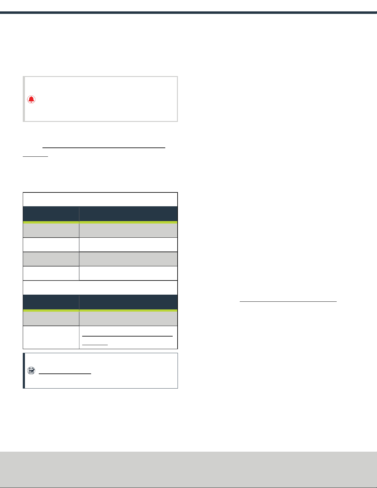
1.2 PRODUCT INFORMATION
Product: Automatic Tool Changer (ATC)for PCNC 1100 Series 3
(PN39009)
The Automatic Tool Changer (ATC) holds up to 12 tools in a single
tray. If your program requires more tools, the ATC changes tools
automatically for all tools assigned to the tray, and pauses for a
manual tool change for all tools not assigned to the tray.
Automatic Tool Changer (ATC)for 1100M
Quantity Description
1 ATCAssembly
3 Fixed Standoff Assembly (PN35832)
10 Plastic Screw (PN32173)
1 Tilt Standoff Assembly (PN35911)
MMachine ATC Retrofit for PCNC 1100 Series 3 (PN39007)
Quantity Description
1 ATCLegacy Adapter Cable (PN38661)
1Coolant Hose Bracket Kit for PCNC 1100
(PN 37258)
Note: If any of these items are missing, we can help. Email
support@tormach.com to contact Tormach Technical
Support for guidance on how to proceed.
1.3 REQUIRED TOOLS
This procedure requires the following tools. Collect them before you
begin.
1.3.1 Required Tools for Installation
l1-1/2 in. adjustable wrench
lMarker
lMetric hex wrench set
lPhillips screwdriver
lSmall, flat-head screwdriver
lSnips
lSocket wrench, and a 13 mm socket
1.3.2 Required Tools for Verification
lMachinist's square, between 6 in. and 9 in. (152 mm and 229
mm)
lStraight rod (for Tormach Tooling System (TTS) tool holder),
between 8 in. and 12 in. (203 mm and 305 mm)
lTormach Tooling System (TTS) tool holder (for alignment rod)
1.4 AIR REQUIREMENTS
You must verify that the site conforms to the following air supply
requirements.
lAir Pressure Between 90 psi and 120 psi (620 kPa to 825
kPa).
If the air supply is more than 120 psi (825 kPa), you must use
a regulator.
lDry Air We recommend using a compressed air dryer,
desiccator, or filter between the air compressor and the
machine.
lLubricated Air You must lubricate the air with air tool oil.
Use the FRLFilter-Regulator-Lubricator (PN 32457) or similar
for this purpose.
Page 2
©Tormach® 2019
Specifications subject to change without notice.
tormach.com
TD10559: Owner's Guide: M ATC Retrofit for PCNC 1100 Series 3 (1119A)
TECHNICAL DOCUMENT
2.1 SETUP
Complete the following steps in the order listed:
2.1.1 Update PathPilot 3
2.1.2 Prepare the Machine 4
2.1.3 Install the Automatic Tool Changer (ATC) 4
2.1.4 Make Final Alignments to the Automatic Tool Changer
(ATC) 16
2.1.1 Update PathPilot
Before using the ATC, you must verify that the PathPilot
controller is updated to PathPilot v2.1.4 or higher. This version
of PathPilot has settings required to use the ATC. Depending
on the version you're using, do one of the following:
ov2.1.4 or Higher Go to "Prepare the Machine" (on the
next page).
ov2.1.3 or Lower Either "Download and Install an Update
File" (below) or "Install an Update File from a USB Drive"
(below).
Download and Install an Update File
Note: Downloading and installing an update file requires
an Internet connection. From the PathPilot interface,
confirm that the Internet button LEDlight is on.
1. Confirm that the PathPilot controller is powered on and out of
Reset mode.
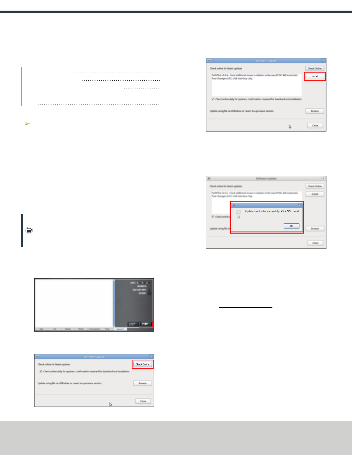
2. From the PathPilot interface, on the Status tab, select Update.
Figure 2-1: Update button on the Status tab.
3. From the Software Update dialog box, select Check Online.
Figure 2-2: Software Update dialog box.
4. Select Install.
Figure 2-3: Install button on the Software Update dialog
box.
The update file is downloaded, and a notification dialog box
displays.
5. From the dialog box, select OK.
Figure 2-4: OKbutton on the dialog box.
The update file is installed on the PathPilot controller.
6. Follow the on-screen instructions to restart the PathPilot
controller.
Install an Update File from a USB Drive
1. From tormach.com/pp-updates, download the most recent
PathPilot update file.
2. Transfer the PathPilot update file to a USB drive.
3. Put the USBdrive into the PathPilot controller.
4. Confirm that the PathPilot controller is powered on and out of
Reset mode.
Page 3
©Tormach® 2019
Specifications subject to change without notice.
tormach.com
TD10559: Owner's Guide: M ATC Retrofit for PCNC 1100 Series 3 (1119A)
TECHNICAL DOCUMENT

5. From the PathPilot interface, on the Status tab, select Update.
Figure 2-5: Update button on the Status tab.
6. From the Software Update dialog box, select Browse.
Figure 2-6: Software Update dialog box.
7. From the Browsedialog box, select USB.
Figure 2-7: Browse dialog box.
8. Select the desired update file, and then select Update.
Figure 2-8: Update button.
The update file is installed on the PathPilot controller.
9. Follow the on-screen instructions to restart the PathPilot
controller.
2.1.2 Prepare the Machine
1. If there's a tool holder in the spindle, remove it.
2. Remove any accessories or fixtures from the machine table.
3. Center the machine table: from the PathPilot interface, in the
MDILine DRO field, type G20 G53 G1 X9 Y-4.75 Z0
F20. Then select the Enter key.
WARNING! Electrical Shock Hazard: You must power
off the machine before making any electrical
connections. If you don't, there's a risk of
electrocution or shock.
4. Power off the machine and the PathPilot controller.
a. Push in the Emergency Stop button on the operator panel,
which removes power to motion control.
b. From the PathPilot interface, select Exit.
c. Turn the Main Disconnect switch to OFF on the side of the
electrical cabinet.
2.1.3 Install the Automatic Tool Changer (ATC)
Complete the following steps in the order listed:
Disassemble the Coolant Hose 5
Install the Air Cylinder 5
Mount the Automatic Tool Changer (ATC) Bracket 6
Install the Main Assembly 6
Page 4
©Tormach® 2019
Specifications subject to change without notice.
tormach.com
TD10559: Owner's Guide: M ATC Retrofit for PCNC 1100 Series 3 (1119A)
TECHNICAL DOCUMENT

Level the Automatic Tool Changer (ATC) 7
Make Air Connections 9
Make Electrical Connections 9
Verify the Installation 13
Adjust the Power Drawbar 14
Disassemble the Coolant Hose
Use the provided kit to disassemble and relocate the coolant hose.
To disassemble the coolant hose:
1. Find and read the machine serial number. Depending on your
specific machine, do one of the following:
lSerial Number 80075 and Below Go to Step 2.
lSerial Number 80076 and AboveGo to Step 4.
2. Use the relocation bracket as a template: put it behind the
spindle — verifying that it's flush with the right edge of the
spindle head — and then use a marker to mark the location of
its holes.
Figure 2-9: Relocation bracket used as a template to mark
the hole locations.
3. Drill and tap a hole for a 6 mm screw in the locations that you
marked in Step 2.
4. Remove the 1/4-in. coolant hose and the coolant hose mount
bracket from the side of the spindle head, and then set both
aside.
Figure 2-10: Flood coolant kit installed on the spindle head.
5. Attach the coolant hose mount bracket to the relocation
bracket with the two screws from the coolant hose mount
bracket.
Figure 2-11: Coolant hose mount bracket attached to the
relocation bracket.
6. Attach the relocation bracket below the spindle head.
Figure 2-12: Relocation bracket mounted below the spindle
head.
Install the Air Cylinder
1. Attach the air cylinder on to the ATC main assembly.
Figure 2-13: Putting the air cylinder into the ATC main
assembly.
Page 5
©Tormach® 2019
Specifications subject to change without notice.
tormach.com
TD10559: Owner's Guide: M ATC Retrofit for PCNC 1100 Series 3 (1119A)
TECHNICAL DOCUMENT

2. Secure the air cylinder to the ATC main assembly with a 12
mm hex wrench (provided) and two M14 × 20 mm socket
head cap screws.
Figure 2-14: Putting the air cylinder hardware into the air
cylinder.
3. Connect the air lines from the ATC main assembly to the air
cylinder as follows:
lConnect the short air line to the front of the cylinder.
lConnect the long air line to the back of the cylinder.
Mount the Automatic Tool Changer (ATC) Bracket
1. Identify the four provided standoffs that are used to mount
the ATC to the Z-column:
lThree fixed standoffs
lOne tilt standoff
2. Remove the flange nuts and the washers from the standoffs,
and then set them aside.
3. Identify and remove the four set screws on the Z-column with
a flat-blade screwdriver.
4. Install the four standoffs on the Z-column as shown in the
following image.
Figure 2-15: Four standoffs installed on the Z-column.
5. Securely tighten the standoffs on the Z-column with a 1-1/2
in. adjustable wrench.
6. Put the ATC mounting bracket on the standoff's threaded
studs as shown in the following image.
Figure 2-16: ATC mounting bracket moving on to the four
standoffs.
Note: Verify that the tilt standoff's eccentric cam fits
into the large slot on the ATC mounting bracket.
7. Secure the bracket by reinstalling the washers and flange nuts
that you removed in Step 2 with a 13 mm socket.
8. Pull the bracket toward the front of the machine. You'll make
adjustments to the location of the bracket later in this
procedure, but we recommend starting with it moved
forward.
Install the Main Assembly
1. Remove the four preinstalled M8 × 1.25 - 16 mm socket head
cap screws and washers from the bottom of the ATC electrical
cabinet. Then, set all aside for later use.
CAUTION! Team Lift Required:You must have the
aid of more than one person to lift and move the
object. The object is heavy, and lifting it by yourself
can cause serious injury.
Page 6
©Tormach® 2019
Specifications subject to change without notice.
tormach.com
TD10559: Owner's Guide: M ATC Retrofit for PCNC 1100 Series 3 (1119A)
TECHNICAL DOCUMENT
2. Lift the ATC main assembly on to the mounting bracket.
Figure 2-17: ATC main assembly positioned above the
mounting bracket.
3. Align the locating pin on the ATC main assembly with the
matching hole in the mounting bracket.
4. Secure the ATC main assembly to the mounting bracket with
the four M8 × 1.25 - 16 mm socket head cap screws and
washers that you set aside in Step 1.
Level the Automatic Tool Changer (ATC)
This section gives instructions to roughly level the ATC on the
machine by using a long, straight rod. More adjustments are made
later in the installation procedure.
NOTICE! After the initial installation, you must level the ATC. If
you don't, there's a risk of machine damage.
Complete the following steps in the order listed:
Prepare the Machine 7
Examine Perpendicularity in the Y Direction 7
Examine Perpendicularity in the X Direction 8
Examine the Alignment of the Carousel Door Opening 8
Prepare the Machine
1. Push the tool tray toward the spindle.
Figure 2-18: Tool tray moved in toward the spindle.
2. Verify that the linear bearing on the ATC is flush with the ATC
main assembly.
Figure 2-19: Linear bearing flush with the ATC main
assembly.
3. Find a straight rod between 8 in. and 12 in. (203 mm and 305
mm) long. Verify that it's straight: roll it on a known flat
surface (like a granite surface plate).
Note: You'll use the rod to verify that the ATC is
correctly installed on the mill, so it must be straight.
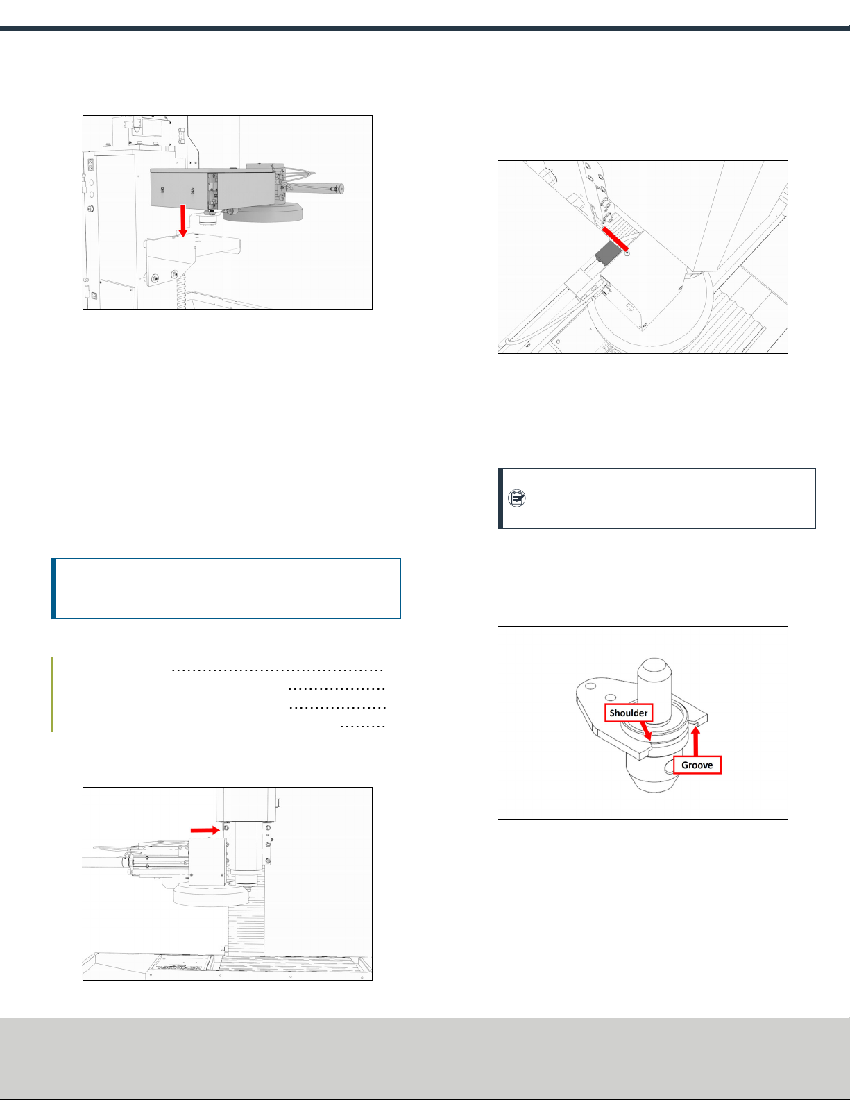
4. Put the alignment rod into a tool holder.
5. Put the tool holder into the fork so that the groove in the tool
holder slides into the fork. Don't rest the tool holder on top of
the fork.
Figure 2-20: Groove on a Tormach Tooling System (TTS)
aligned with the shoulder of an ATC fork.
6. Put a machinist's square on the machine table.
Examine Perpendicularity in the Y Direction
1. Verify that the rod is perpendicular to the machine table in
the Y direction: compare the rod's position to the vertical edge
of the machinist's square.
Page 7
©Tormach® 2019
Specifications subject to change without notice.
tormach.com
TD10559: Owner's Guide: M ATC Retrofit for PCNC 1100 Series 3 (1119A)
TECHNICAL DOCUMENT

lIf the rod is perpendicular to the vertical edge of the
machinist's square, go to "Examine Perpendicularity in the
X Direction" (below).
lIf the rod must be adjusted, go to Step 2.
2. Loosen the flange nuts on the standoffs.
3. Turn the tilt standoff with an adjustable wrench, and slowly
pivot the ATC until the rod is perpendicular to the vertical
edge of the machinist's square.
Figure 2-21: Tilt standoff.
4. Tighten the flange nuts with a 13 mm socket.
5. Reexamine the alignment of the ATC in the Y direction. If the
rod isn't perpendicular to the vertical edge of the machinist's
square, repeat Steps 2 through 5.
Examine Perpendicularity in the X Direction
1. Verify that the rod is perpendicular to the machine table in
the X direction: compare the rod's position to the vertical edge
of the machinist's square.
lIf the rod is perpendicular to the vertical edge of the
machinist's square, go to "Examine the Alignment of the
Carousel Door Opening" (below).
lIf the rod must be adjusted, go to Step 2.
2. Loosen the two socket head cap screws on the linear rails.
Figure 2-22: Socket head cap screws on the linear rails.
3. Slowly pivot the linear rails up or down until the rod is
perpendicular to the vertical edge of the machinist's square.
4. Tighten the socket head cap screws.
5. Reexamine the alignment of the ATC in the X direction. If the
rod isn't perpendicular to the vertical edge of the machinist's
square, repeat Steps 2 through 5.
Examine the Alignment of the Carousel Door Opening
1. Remove the tool holder from the fork, and set it aside.
Note: You'll need this tool later in the installation
procedure to make further alignments.
2. Power on the machine and the PathPilot controller.
a. Turn the Main Disconnect switch to ONon the side of the
electrical cabinet.
b. Twist out the Emergency Stop button on the operator
panel, which enables movement to the machine axes and
the spindle.
c. Press the Reset button on the operator panel.
d. Bring the machine out of reset and reference it.
3. Verify that the ATC is all the way forward (toward the
spindle), and then slowly move the Z-axis down (-Z) to
examine the clearance of the carousel door opening.
4. Verify that the carousel door opening is approximately equal
to the front back and left of the spindle mounting flange:
lIf the carousel door opening is approximately equal, go to
Step 8.
Figure 2-23: Distance between the carousel door
opening and the spindle mounting flange.
lIf the carousel door opening must be adjusted, go to Step
5.
Page 8
©Tormach® 2019
Specifications subject to change without notice.
tormach.com
TD10559: Owner's Guide: M ATC Retrofit for PCNC 1100 Series 3 (1119A)
TECHNICAL DOCUMENT

5. Loosen the four socket head cap screws that secure the ATC
main assembly to the mounting bracket with a 6 mm hex
wrench.
Figure 2-24: Socket head cap screws securing the ATC main
assembly to the mounting bracket.
6. Adjust the carousel door opening as required:
lIf the Carousel Door Opening is Contacting the Front
Pivot the ATC around the locating pin on the bottom of the
mounting bracket toward the front of the machine (closer
to you).
lIf the Carousel Door Opening is Contacting the Back
Pivot the ATC around the locating pin on the bottom of the
mounting bracket toward the back of the machine (closer
to the machine column).
lIf the Carousel Door Opening is Contacting the Left
Loosen the four flange nuts that attach the mounting
bracket to the column to move the bracket forward or
backward.
Note: Moving the ATC mounting bracket could
change the position of the tilt standoff (on the Z-
column). If you move it, you must verify that the
ATC is still correctly installed; go to "Examine
Perpendicularity in the Y Direction" (page7).
Repeat this step as needed.
7. Tighten the socket head cap screws and the flange nuts (if you
loosened them in Step 5).
8. Move the tool tray to its retracted position.
9. Center the machine table: from the PathPilot interface, in the
MDILine DRO field, type G20 G53 G1 X9 Y-4.75 Z0
F20. Then select the Enter key.
10. Power off the machine and the PathPilot controller.
a. Push in the Emergency Stop button on the operator panel,
which removes power to motion control.
b. From the PathPilot interface, select Exit.
c. Turn the Main Disconnect switch to OFF on the side of the
electrical cabinet.
Make Air Connections
1. Cut the cable tie that secures the ATC cables and plastic tubes
together with snips.
2. Route the loose ends of the two 1/4 in. plastic tubes
connected to the ATC main assembly through the enclosure
knockout, up the energy chain, and toward the Power
Drawbar.
WARNING! Crush Hazard: If the ATC isn't completely
retracted, it could move once the air is reconnected.
When you reconnect the air, you must keep your
hands away from the ATC.
3. Connect the loose ends of the 1/4 in. plastic tubes in the
following order:
a. Connect the Retract (PDBBottom) airline to the bottom
push-to-connect elbow on the Power Drawbar.
b. Connect the Advance (PDBTop) airline to the top push-to-
connect elbow on the Power Drawbar
c. Connect the air supply line from the FRL to the air in port in
the ATC main assembly, as shown in the following image.
Figure 2-25: Air in port in the ATC main assembly.
d. If you haven't already done so, connect your shop's air
supply to the FRL.
Make Electrical Connections
Complete the following steps in the order listed:
Rewire the Power Drawbar Board 10
Page 9
©Tormach® 2019
Specifications subject to change without notice.
tormach.com
TD10559: Owner's Guide: M ATC Retrofit for PCNC 1100 Series 3 (1119A)
TECHNICAL DOCUMENT
Connect the ATCLegacy Adapter Cable 10
Rewire the ATC Board 13
Rewire the Power Drawbar Board
If you previously installed the Power Drawbar board, you must
rewire it.
To rewire the Power Drawbar board:
WARNING! Electrical Shock Hazard: You must power off
the machine before making any electrical connections. If
you don't, there's a risk of electrocution or shock.
1. Power off the machine and the PathPilot controller.
a. Push in the Emergency Stop button on the operator panel,
which removes power to motion control.
b. From the PathPilot interface, select Exit.
c. Turn the Main Disconnect switch to OFF on the side of the
electrical cabinet.
2. Open the electrical cabinet door.
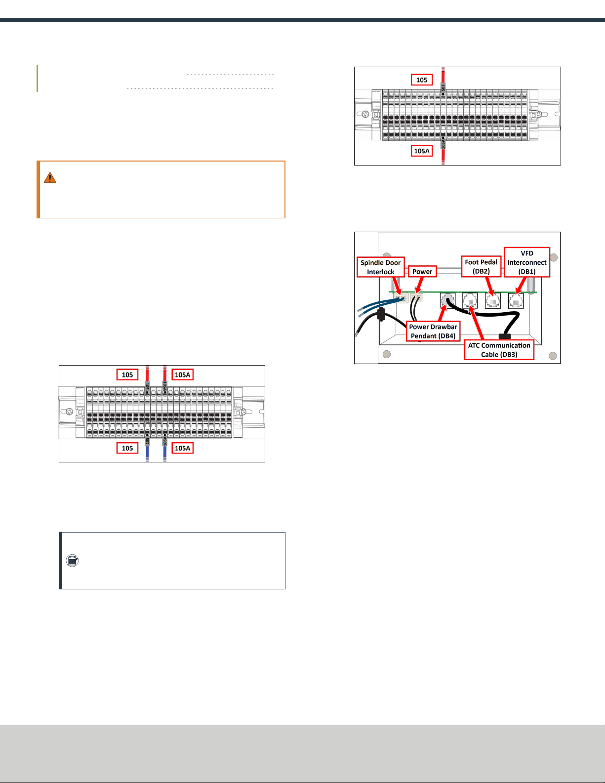
3. Locate blue wires 105 and 105A on the terminal block in the
electrical cabinet.
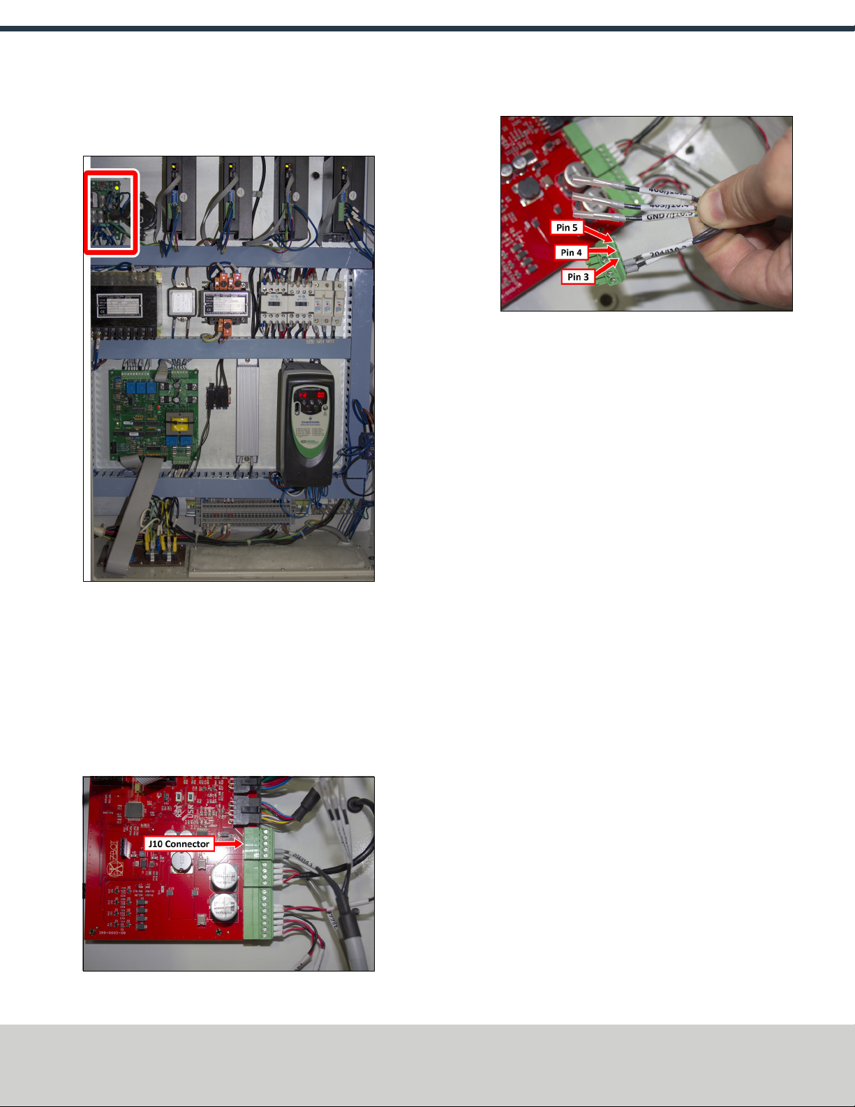
Figure 2-26: Current wire configuration on the terminal
block.
4. Remove blue wires 105 and 105A.
5. Locate red wire 105A on the terminal block. Then, remove it.
Note: During the original procedure to install the
Power Drawbar, wire 105 was given a new label,
making it wire 105A.
6. Connect red wire 105A to the slot opposite red wire 105 on
the terminal block.
Figure 2-27: New wire configuration on the terminal block.
7. In the Power Drawbar control assembly box, locate the blue
spindle door interlock wires on the Power Drawbar board.
Then, unplug them.
Figure 2-28: Current wire configuration on the Power
Drawbar board.
8. Pull the loose blue spindle door interlock wires from the
Power Drawbar control assembly box, through the Z column,
and out of the machine. Then, discard them.
9. In the Power Drawbar control assembly box, locate the power
wire connector on the Power Drawbar board. Then, unplug it.
10. Pull the loose power wire from the Power Drawbar control
assembly box and out of the machine. Then, discard it.
11. In the Power Drawbar control assembly box, locate the VFD
interconnect cable (from DB1) on the Power Drawbar board.
Then, unplug it.
Connect the ATCLegacy Adapter Cable
1. Connect the ATCLegacy Adapter Cable to the ATC power cable
on the main assembly.
2. Route the loose wires from the ATCLegacy Adapter Cable out
of the enclosure and toward the electrical cabinet on the back
of the machine.
Page 10
©Tormach® 2019
Specifications subject to change without notice.
tormach.com
TD10559: Owner's Guide: M ATC Retrofit for PCNC 1100 Series 3 (1119A)
TECHNICAL DOCUMENT

3. Use any open access hole in the bottom of the electrical
cabinet to route the loose wires into the electrical cabinet.
Figure 2-29: Access hole in the bottom of the electrical
cabinet.
4. Remove the wire trough covers in the electrical cabinet.
5. Identify wires T1 and B3 on the ATCLegacy Adapter Cable.
Then, route them through the wire troughs toward the
variable frequency drive (VFD).
Figure 2-30: VFD in the electrical cabinet.
6. Use a Phillips screwdriver to remove the cross-head screw on
the VFD, and then remove the VFD faceplate.
Figure 2-31: Removing the faceplate from the VFD.
7. If you previously installed the Power Drawbar board, you must
remove the VFDinterconnect cable. Identify it on the VFD and
remove it. Then, pull the loose cable out of the machine, and
discard it.
Figure 2-32: VFDinterconnect cable connected to the VFD.
8. Identify slots T1 and B3 on the VFD. You'll make connections
in both slots to connect the ATCLegacy Adapter Cable.
Figure 2-33: Slot identification on the VFD.
Page 11
©Tormach® 2019
Specifications subject to change without notice.
tormach.com
TD10559: Owner's Guide: M ATC Retrofit for PCNC 1100 Series 3 (1119A)
TECHNICAL DOCUMENT

9. Remove wire T1 from the VFD, and then insert it in to the
open slot in the T1 lever nut on the ATCLegacy Adapter Cable.
Note: If you have an (optional) load meter, your
VFDhas an extra wire in slot T1. Remove it from the
VFD, and then insert it into the remaining open slot
in the T1 lever nut on the ATCLegacy Adapter Cable.
10. Completely push the lever down on the T1 lever nut to latch
the wire. Verify that the lever is latched.
11. Connect the loose wire from the T1 lever nut in to slot T1 on
the VFD.
Figure 2-34: T1 lever nut connected to slot T1 on the VFD.
12. Connect the loose wire from the B3/B5 lever nut on the
ATCLegacy Adapter Cable to slot B3 on the VFD.
Note: If you have an (optional) load meter, your
VFDhas an extra wire in slot B3. Remove it from the
VFD, and then insert it into the remaining open slot
in the B3/B5 lever nut on the ATCLegacy Adapter
Cable.
13. Replace the VFD faceplate.
14. Identify the green and yellow ground wire on the ATCLegacy
Adapter Cable. Then, route it through the wire troughs toward
the ground terminal block.
Figure 2-35: Terminal block in the electrical cabinet.
15. Connect the ground wire in to any open slot on the ground
terminal block.
Page 12
©Tormach® 2019
Specifications subject to change without notice.
tormach.com
TD10559: Owner's Guide: M ATC Retrofit for PCNC 1100 Series 3 (1119A)
TECHNICAL DOCUMENT
16. Identify wires 503 and 504 on the ATCLegacy Adapter Cable.
Then, route them through the wire troughs toward the DC-
BUSboard.
Figure 2-36: DC-BUSboard in the electrical cabinet.
17. Connect wire 503 to the TC+ terminal on the DC-BUSboard.
18. Connect wire 504 to the TC- terminal on the DC-BUSboard.
Rewire the ATC Board
1. Unlock and open the lid on the ATC main assembly with a
large, flat-blade screwdriver.
2. Identify the J10 connector on the ATC board, and then unplug
it from the board.
Figure 2-37: J10 connector on the ATC board.
3. Identify the loose ends of wires 403, 408, and GND.
Figure 2-38: Loose wires on the J10 connector from the ATC
board.
4. Remove the plastic wire protectors from the ferrule ends.
5. Use a small, flat-blade screwdriver to connect the following
wires to the J10 connector:
lWire 408 to pin 3
lWire 403 to pin 4
lWire GND to pin 5
6. Plug the J10 connector back in the ATC board.
7. Close the lid on the ATC main assembly and lock it.
Verify the Installation
1. Power on the machine and the PathPilot controller.
a. Turn the Main Disconnect switch to ONon the side of the
electrical cabinet.
b. Twist out the Emergency Stop button on the operator
panel, which enables movement to the machine axes and
the spindle.
c. Press the Reset button on the operator panel.
d. Bring the machine out of reset and reference it.
2. If you have not yet done so, you must make sure that the
PathPilot controller is updated to the latest version of
PathPilot.
For information, see "Update PathPilot" (page3).
Page 13
©Tormach® 2019
Specifications subject to change without notice.
tormach.com
TD10559: Owner's Guide: M ATC Retrofit for PCNC 1100 Series 3 (1119A)
TECHNICAL DOCUMENT

3. From the PathPilot interface, on the Settings tab, select the
ATC radio button.
Figure 2-39: ATC radio button on the Settings tab.
The ATC tab appears in the PathPilot interface.
Note: If prompted, you may need to update the
firmware for the ATC. Follow the on-screen
instructions.
4. Load a tool into the spindle:
a. Push and hold the collet open button on the side of the
ATC.
Figure 2-40: Collet open button on the side of the ATC.
The collet opens.
b. Load a tool into the spindle.
c. Release the button.
The collet closes.
5. From the PathPilot interface, on the Main tab, in the RPM
DRO field, type 1000. Then select the Enter key.
6. Select FWD.
The spindle starts.
7. From the Status tab, make sure that the VFD Running green
light comes on.
Figure 2-41: VFDRunning light on the Status tab.
Note: If the VFDRunning light did not come on in the
previous step, we can help. Email
support@tormach.com to contact Tormach Technical
Support for guidance on how to proceed.
8. Select Stop.
The spindle stops.
Adjust the Power Drawbar
If you have not yet done so, you must adjust the Power Drawbar.
Complete the following steps in the order listed:
Adjust the Drawbar Tension 14
About Drawbar Tension 15
Adjust the Initial Setup 15
Adjust the Drawbar Tension
This adjustment sets the highest possible drawbar tension while
still allowing the Power Drawbar cylinder to release the tool. For
information, see "About Drawbar Tension" (on the next page).
NOTICE! After the initial installation, you must examine the
drawbar tension weekly. During periods of heavy use, examine
the drawbar tension more frequently. If you don't, there's a
risk of tool pull-out.
To adjust the drawbar tension:
1. Put an empty Tormach Tooling System (TTS) tool holder into
the collet.
2. While using one hand to support the tool holder, use the other
to push the Release Tool button.
Page 14
©Tormach® 2019
Specifications subject to change without notice.
tormach.com
TD10559: Owner's Guide: M ATC Retrofit for PCNC 1100 Series 3 (1119A)
TECHNICAL DOCUMENT

3. Dependingon whether the tool holder releases or not, do one
of the following:
lIf the Tool Holder Releases Tighten the Power Drawbar
in quarter-turn increments with two adjustable wrenches.
After each turn, push the Release Tool button. Stop when
the tool holder does not release. Then, loosen the Power
Drawbar one quarter-turn with two adjustable wrenches.
lIf the Tool Holder Doesn't Release Loosen the Power
Drawbar in quarter-turn increments with two adjustable
wrenches while pushing the Release Tool button. Stop
when the tool holder releases.
4. Make a visual reference to help you set or adjust the drawbar
tension in the future: use a paint pen to make a witness mark
on both the head of the drawbar and the end of the spindle.
About Drawbar Tension
While machining, the Tormach Tooling System (TTS) collet holds a
Tormach Tooling System (TTS) tool holder in the spindle by applying
a clamping force to both the shank and the shoulder of the tool. The
tension force that is applied to the drawbar pulls the Tormach
Tooling System (TTS) collet into the spindle taper, which then
applies the clamping force to the Tormach Tooling System (TTS)
tool.
The force on the drawbar — known as drawbar tension — is applied
differently depending on the tool changing method:
lAutomatic (using the Power Drawbar) Tension is applied
by the compressed spring washers.
lManual Tension is applied when you tighten the drawbar into
the collet using a wrench.
Adjust the Initial Setup
In this adjustment, you'll verify that there's enough clearance
between the end of the drawbar and the Power Drawbar cylinder.
NOTICE! If you don't do this adjustment, there's a risk that the
drawbar can loosen, or that operations can be louder than
normal.
1. Examine the space between the hex head screw on the Power
Drawbar cylinder's rod and the top of the drawbar.
Figure 2-42: Correctly spaced drawbar and Power Drawbar
cylinder.
2. Verify that the gap is between 3/64 in. and 1/8 in. (1 mm and
3 mm). Depending on the size of the gap, do one of the
following:
lBetween 3/64 in. and 1/8 in. (1 mm and 3 mm) You
have completed adjusting the initial setup. Go to
Operation.
lLess Than 3/64 in. (1 mm) Go to Step 3.
3. Disconnect the shop's air supply from the Power Drawbar
button.
4. Pull out the quick-release pin.
5. Pivot the Power Drawbar cylinder assembly to the left so that
you can access the Power Drawbar cylinder's rod.
Figure 2-43: Power Drawbar cylinder pivoted to the left.
Page 15
©Tormach® 2019
Specifications subject to change without notice.
tormach.com
TD10559: Owner's Guide: M ATC Retrofit for PCNC 1100 Series 3 (1119A)
TECHNICAL DOCUMENT

6. Remove the hex head screw on the Power Drawbar cylinder’s
rod with an adjustable wrench, and set it aside.
Figure 2-44: Hex head screw on the Power Drawbar
cylinder's rod.
7. Remove the M16 washer from the Power Drawbar cylinder’s
rod, and set it aside.
Figure 2-45: M16 washer removed from the Power
Drawbar cylinder's rod.
8. Put the hex head screw back in, and then tighten it completely
with an adjustable wrench.
9. Pivot the Power Drawbar cylinder to the original location.
10. Push in the quick-release pin.
11. Reconnect the shop's air supply to the Power Drawbar button.
12. Examine the space between the hex head screw on the Power
Drawbar cylinder’s rod and the top of the drawbar.
13. Verify that the gap is between 3/64 in. and 1/8 in. (1 mm and
3 mm). Depending on the size of the gap, do one of the
following:
lBetween 3/64 in. and 1/8 in. (1 mm and 3 mm) You
have completed adjusting the initial setup. Go to
Operation.
lLess Than 1/8 in. (1 mm) Go to Step 14.
14. Find the three provided M14 flat washers.
15. Put one M14 flat washer under each mounting post on the
Power Drawbar cylinder.
2.1.4 Make Final Alignments to the Automatic Tool
Changer (ATC)
Complete the following steps in the order listed:
Adjust the Tool Tray Load Position 16
Verify the Alignment 17
Set the Tool Change Height 17
Adjust for Rotational Play 17
Adjust the Tool Tray Load Position
1. Verify that there's no tool in the spindle.
2. From the PathPilot interface, on the ATC tab, select Ref Tool
Tray.
Figure 2-46: Ref Tool Tray button on the ATCtab.
The tool tray spins.
Note: You're only required to reference the tool tray
once, unlike the mill axes’ referencing procedure.
3. Select Go to Tray Load Position.
Figure 2-47: Go to Tray Load Position button on the ATC
tab.
4. When prompted, select OK.
The tool tray moves forward.
5. Put the tool holder with the rod into the fork.
6. From the PathPilot interface, slowly jog the Z-axis down (-Z)
to bring the spindle nose toward the tool in the tool tray.
7. Make sure that the tool’s shank is aligned concentrically with
the collet in the spindle.
Page 16
©Tormach® 2019
Specifications subject to change without notice.
tormach.com
TD10559: Owner's Guide: M ATC Retrofit for PCNC 1100 Series 3 (1119A)
TECHNICAL DOCUMENT
8. If the tool's shank isn't aligned, do the following:
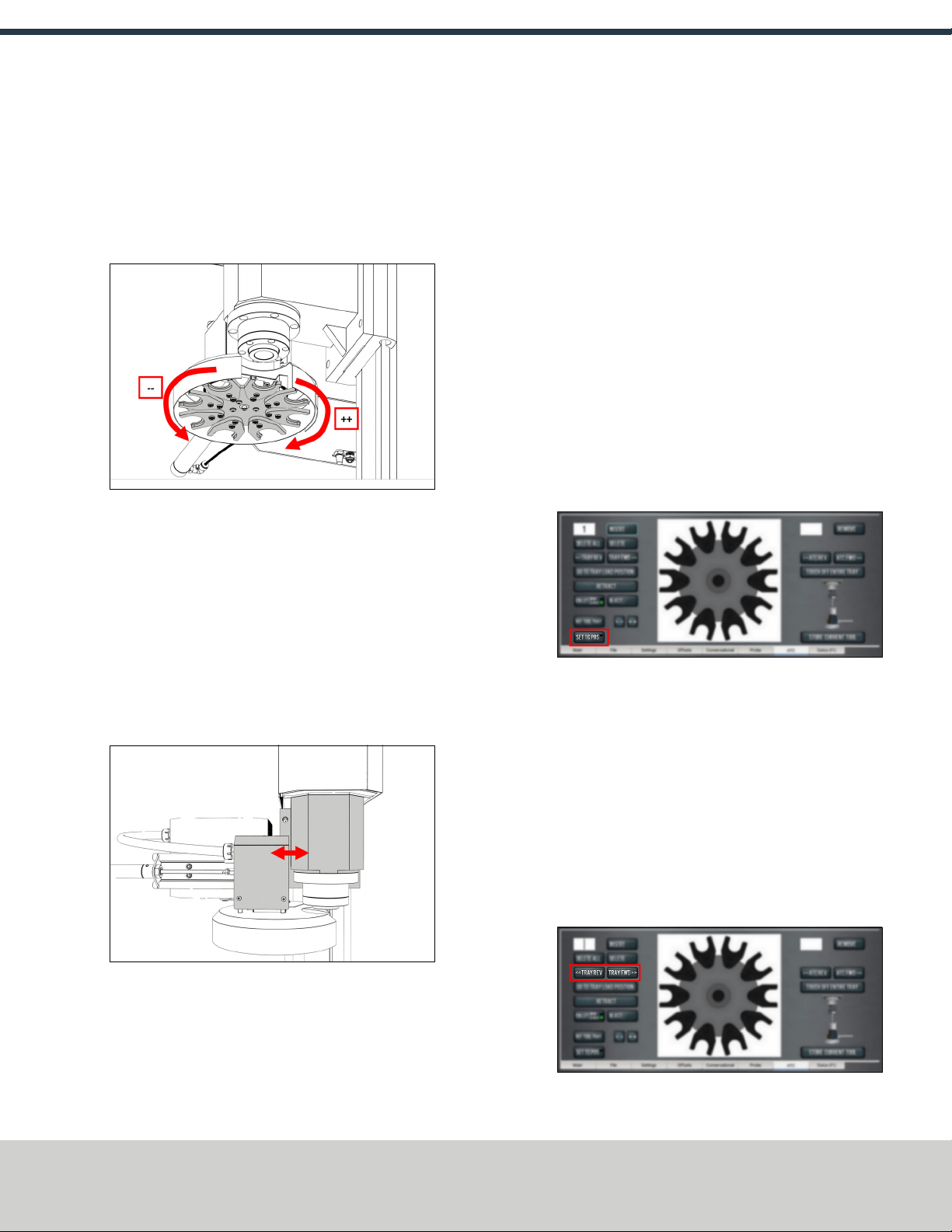
lAdjust the Alignment of the Tool in the Y Direction
(toward or away from the Z column) Determine if the
tray must move clockwise or counterclockwise. From the
PathPilot interface, in the ATC tab, either select -- to step
the tool tray counterclockwise or ++ to step the tool tray
clockwise.
Figure 2-48: Moving the tool tray clockwise or
counterclockwise.
lAdjust the Alignment of the Tool in the X Direction
(left or right) Determine if the tray must move left or
right. Use two wrenches to loosen the jam nut on the end
of the cylinder rod, making sure that you don't spin the rod
end when adjusting the jam nut. Then, either turn the rod
end one-half turn further on to the cylinder rod to move the
tool tray to the left, or turn it one-half turn off of the
cylinder rod to move the tool tray to the right. Once
finished, tighten the jam nut.
Figure 2-49: Moving the tool tray left or right.
Repeat adjustments until the tool's shank is concentric with
the collet in the spindle.
9. From the PathPilot interface, on the ATC tab, select Retract.
Verify the Alignment
1. From the PathPilot interface, select Go to Tray Load Position.
2. Slowly jog the Z-axis down (-Z) over the tool’s shank.
3. Verify that the tool’s shank moves freely into the collet.
4. Depending on the tool's shank movement, do one of the
following:
lMoves Freely Go to "Set the Tool Change Height"
(page20).
lDoesn't Move Freely This indicates that the ATC is
misaligned and you must realign it. Go to "Adjust the Tool
Tray Load Position" (on the previous page).
Set the Tool Change Height
1. From the PathPilot interface, slowly jog the Z-axis down (-Z)
over the tool. Stop jogging when the spindle nose just makes
contact with the shoulder of the tool holder.
2. On the ATC tab, select Set TC POS.
Figure 2-50: Set TCPOS button on the ATC tab.
The tool change position is set.
Adjust for Rotational Play
There's a small amount of rotational play built into the Automatic
Tool Changer (ATC) carousel. This play allows for some
misalignment during tool changes, and you must adjust for it in both
directions. The taper on the tool shank also helps align the tool
during a tool change.
To adjust for rotational play:
1. From the PathPilot interface, on the ATC tab, select Tray Fwd
to rotate the tray clockwise (forward) one full tool slot.
Page 17
©Tormach® 2019
Specifications subject to change without notice.
tormach.com
TD10559: Owner's Guide: M ATC Retrofit for PCNC 1100 Series 3 (1119A)
TECHNICAL DOCUMENT

Figure 2-51: Tray FWDand Tray REVbuttons on the
ATCtab.
2. Select Tray Rev to rotate the tray counterclockwise
(backward) one full tool slot.
3. Verify that the tool’s shank is aligned with the collet in the
spindle.
4. Depending on the alignment, do one of the following:
lAligned You have completed aligning the ATC. Remove
the tool from the fork. Go to "Operation" (page19).
lNot Aligned You must readjust the tool tray rotation. Go
to "Adjust the Tool Tray Load Position" (page16).
Page 18
©Tormach® 2019
Specifications subject to change without notice.
tormach.com
TD10559: Owner's Guide: M ATC Retrofit for PCNC 1100 Series 3 (1119A)
TECHNICAL DOCUMENT
3.1 OPERATION
Note: Make sure that there's always a tool holder in the
collet while the machine is not in use. Retracting the
Power Drawbar to the clamped position with no tool holder
in the collet will eventually fatigue the collet, and may
shorten its service life. For more information, refer to the
Power Drawbar documentation.
Read the following sections to understand how to operate the ATC:
3.1.1 Assign Tool Numbers 19
3.1.2 Automatically Load a Tool into the Tool Tray 19
3.1.3 Automatically Unload a Tool From the Tool Tray 19
3.1.4 Load a Tool into the Spindle 19
3.1.5 Manually Load a Tool Into the Tool Tray 20
3.1.6 Manually Unload a Tool From the Tool Tray 20
3.1.7 Retrieve a Tool From the Tool Tray 20
3.1.8 Set the Tool Change Height 20
3.1.9 Switch to Manual Tool Changes 21
3.1.1 Assign Tool Numbers
Use any tool number, from 1-1000, to assign a position in the
tool tray.
3.1.2 Automatically Load a Tool into the Tool Tray
1. Load a tool into the spindle.
2. From the PathPilot interface, on the ATC tab, type the tool
number in the Tool DRO field. Then select the Enter key.
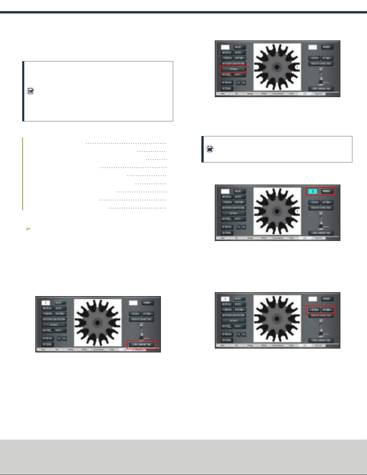
3. Select Store Current Tool.
Figure 3-1: Store Current Tool button on the ATC tab.
The tool is assigned to the nearest open slot. The ATC fetches
the tool from the spindle and stores the tool in the tray. When
stored, the tool number displays on the tray image in the
center of the screen.
4. Click Retract.
Figure 3-2: Retract button on the ATC tab.
The tray returns to the machining position.
3.1.3 Automatically Unload a Tool From the Tool Tray
Note: Typing a new tool number in the Tool DRO field
doesn't remove the tool from its tray assignment.
1. From the PathPilot interface, on the ATC tab, type the tool
number in the Remove DRO field. Then select the Enter key.
Figure 3-3: Remove DROfield on the ATC tab.
2. Select Remove.
The ATC fetches the tool from the tray.
3. Unload the tool from the spindle.
4. From the ATC tab, select ATC FWD or ATC REV.
Figure 3-4: ATCREV and ATCFWD buttons on the ATC tab.
The tray moves to the next location and fetches another tool.
5. Select Retract.
The tray returns to the machining position.
3.1.4 Load a Tool into the Spindle
Load a tool into the spindle:
Page 19
©Tormach® 2019
Specifications subject to change without notice.
tormach.com
TD10559: Owner's Guide: M ATC Retrofit for PCNC 1100 Series 3 (1119A)
TECHNICAL DOCUMENT

1. Push and hold the collet open button on the side of the ATC.
Figure 3-5: Collet open button on the side of the ATC.
The collet opens.
2. Load a tool into the spindle.
3. Release the button.
The collet closes.
Note: If installed, the Power Drawbar button's functionality
is replaced by the button on the ATC.
3.1.5 Manually Load a Tool Into the Tool Tray
1. From the PathPilot interface, on the ATC tab, select Go To
Tray Load Position.
Figure 3-6: Go to Tray Load Position button on the ATCtab.
The spindle head moves up and the ATC moves into the door
open position.
2. Load a tool into an open fork on the tray.
3. From the ATC tab, type the tool number into the Insert DRO
field. Then select the Enter key.
4. Select Insert.
The tool is assigned to the exposed tray slot.
5. Select Tray FWD or Tray REV.
The tray moves to the next slot location.
6. Select Retract.
The tray returns to the machining position.
3.1.6 Manually Unload a Tool From the Tool Tray
1. From the PathPilot interface, on the ATC tab, in the Insert
DRO field, type the tool number. Then select the Enter key.
2. Select Go To Tray Load Position.
The spindle head moves up and the ATC moves into the door
open position.
3. Select Delete.
Figure 3-7: Delete button on the ATCtab.
The tool is unassigned from the tray and the tray moves to
that tool.
4. Select Tray FWD or Tray REV.
The tray moves to the next slot location.
5. Select Retract.
The tray returns to the machining position.
3.1.7 Retrieve a Tool From the Tool Tray
Depending on your workflow, do one of the following from the
PathPilot interface:
oType the command directly into the MDILine DROfield
using the following format:T[TOOL NUMBER] M06
For example, T1 M06
oType the tool number in the Tool DRO field. Then select the
Enter key.
3.1.8 Set the Tool Change Height
1. From the PathPilot interface, slowly jog the Z-axis down (-Z)
over the tool. Stop jogging when the spindle nose just makes
contact with the shoulder of the tool holder.
Page 20
©Tormach® 2019
Specifications subject to change without notice.
tormach.com
TD10559: Owner's Guide: M ATC Retrofit for PCNC 1100 Series 3 (1119A)
TECHNICAL DOCUMENT
Other manuals for ATC
2
Table of contents


