Tormach PSG 612 User manual

QUESTIONS OR COMMENTS?
PLEASE EMAIL US AT:
SUPPORT@TORMACH.COM
OPERATOR MANUAL
TORMACH
PSG 612
2AXIS SEMIAUTOMATIC
PERSONAL SURFACE GRINDER
TORMACH.COM
© 2018 Tormach, Inc. All rights reserved.
UM10159_PSG612_Operators_Manual_0718A


1. Scope of Documentation 2
Customer Service 2
About the PSG 612 2
Intended Use 2
Product Features 2
Components 3
Tool Box Inventory 4
Specifications 5
2. Risks of Machinery 6
Basic Machine Safety 6
Operating Safety 6
Electrical Safety 7
For Lifting 7
For Assembly 7
3. Installation 8
Unpacking 8
Assembly 8
Protecting from Rust 8
Lubrication 8
4. Grinder Operation 11
Control Modes and Power Controls 11
Speed and Feed 11
Wheel On/Wheel Off 11
Start/Stop 11
E-Stop 11
Power Mains 11
Powering Up the Machine 12
Using the Magnetic Chuck 12
5. Working With Wheels 13
Adjusting Table Flags 13
Installing a Grinding Wheel 13
Ring Test 14
Replacing the Hub on a Grinding Wheel 14
Wheel Balancing 15
Dressing a Wheel 16
6. Machine Maintenance 17
Backlash Adjustment 17
Gib Screw Adjustment 17
Changing /Cleaning Air Filters 17
Replacing Fuse 18
Replacing the Y Axis Belt 18
Machine Storage 19
7. Electrical Cabinet Components 20
8. Exploded Views 21
9. Troubleshooting 27
10. Warranty 30
11. Index 32
TABLE OF CONTENTS
UM10159_PSG612_OPERATORS_MANUAL_0718A PB 1UM10159_PSG612_OPERATORS_MANUAL_0718A

The purpose of this manual is to help the reader
understand how to prepare for, operate, and maintain the
Tormach 2-Axis Semi-Automac Personal Surface Grinder
PSG 612.
While the reader may not have an inmate understanding
of the Tormach 2-Axis Semi-Automac Personal
Surface Grinder PSG 612, we assume they have a basic
understanding of how to operate this type of machine.
As with all machinery of this nature, learning the nuances
of operaon is a process that happens through training
and experience. If you are not an experienced operator of
this type of machinery, read through this enre manual,
then learn more from an experienced operator, schooling,
or research before aempng operaons. Following this
advice will help you avoid serious personal injury and get
the best results from your work.
Tormach intends to be as accurate as possible in creang
technical documentaon. That said, periodically manuals
are updated to add or remove content to improve the
overall accuracy and usability. We use an alpha-numeric
revision control method that is idened in the footer of
each page. For example, 0413B is the second update to the
document in the month of April 2013.
The current version of the manual is made available
in electronic format on hp://www.tormach.com/
documents.html. Tormach values customer feedback as it
relates to documentaon. If you have feedback, posive or
construcve, please send an email to
CUSTOMER SERVICE
Tormach provides technical support through mulple
channels. The quickest ways to receive technical support
and the answers you need are through one of the methods
listed below:
• This manual: always the rst place to check
• tormach.com/support
• Email: [email protected]
• Telephone: 608-849-8381
• Fax: 209-885-4534
ABOUT THE PSG 612
Intended Use
The Tormach 2-Axis Semi-Automac Personal Surface
Grinder PSG 612 is a 6” X 12” semi-automac personal
surface grinder. It is intended for use as a general purpose
surface grinder for grinding ferrous materials including cast
iron, mild steel, and alloy steels. Grinding other materials
may be possible, but may require specialized grinding
wheels and or specialized grinding techniques. Tormach
limits support and warranty when products are used
outside the scope of a product’s intended purpose.
All applicable warranes for this equipment are voided
through modicaon to the equipment or use outside
of the Intended Use. Individuals or companies involved
with modifying the equipment or applying the products
assume all consequent liability. Refer to the warranty and
liability secons at the end of this manual for addional
informaon.
Product Features
A surface grinder allows you to smooth the surface of
metallic work pieces, ulizing a semi-automac table that
moves on a horizontal plane and a grinding wheel that
moves along a vercal axis. By mounng a work piece to
the table with a magnec chuck, then moving the table
and the grinding wheel during the grinding process,
extremely small amounts of material can be removed to
create high-tolerance at surfaces.
The PSG 612 is equipped with easy-to-reach front-mounted
handwheels for controlling table movement to posion the
wheel manually.
The table travels in the longitudinal direcon (X) on a
hydrodynamic (oil lm) slideways table, driven by a rack-
and-pinion mechanism. Vercal (Z) travel is driven by a
manually-operated leadscrew with a counterweight for
controlled posioning. Crossfeed travel (Y) is driven by a
leadscrew. Both X and Y are automac and can also be
posioned manually.
The stand doubles as a storage cabinet where you can keep
the necessary tools and extra grinding wheels right where
you need them.
SCOPE OF DOCUMENTATION
UM10159_PSG612_OPERATORS_MANUAL_0718A 23UM10159_PSG612_OPERATORS_MANUAL_0718A
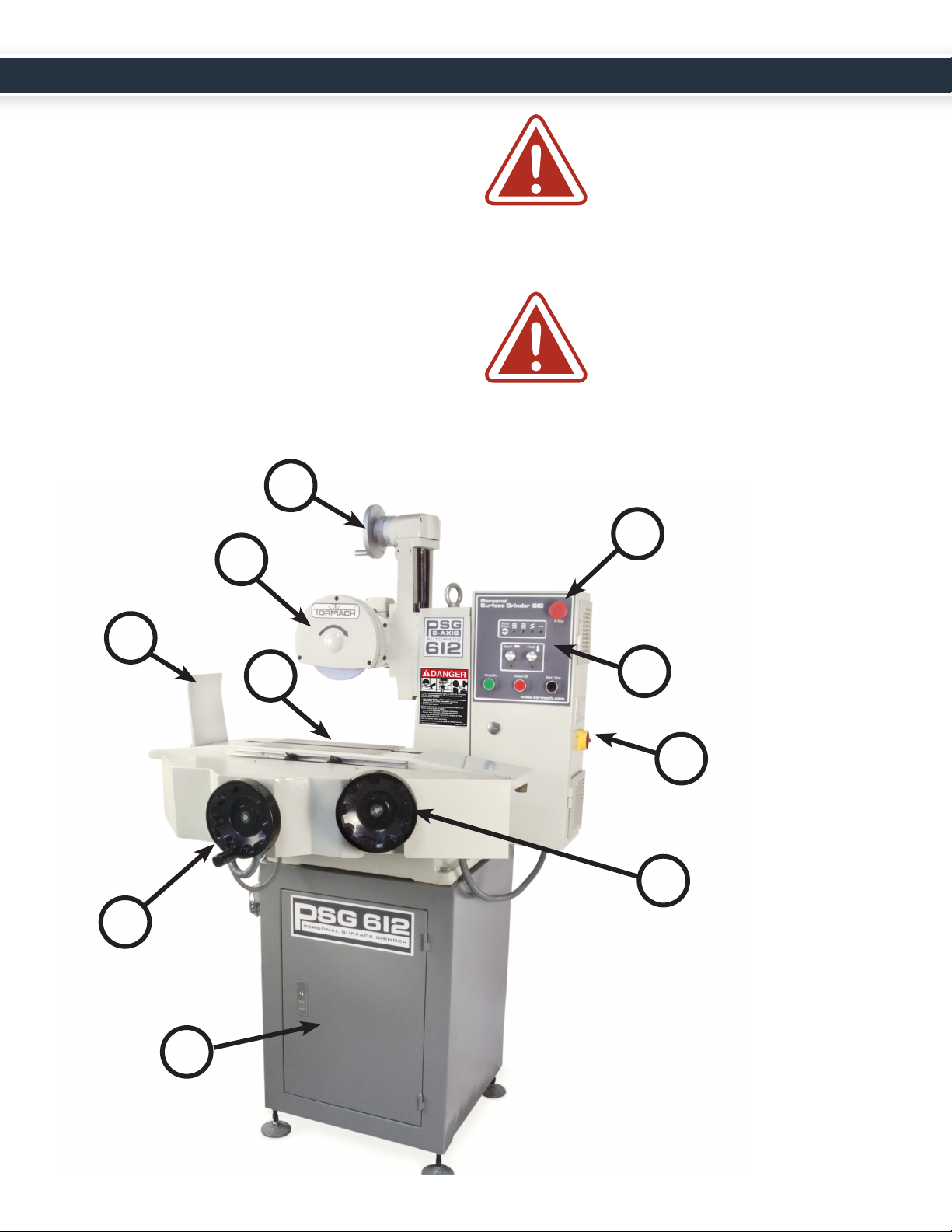
Components
1. Control Panel
2. Power Disconnect
3. Table Jog Handwheel
4. Storage Cabinet
5. Cross Feed Handwheel
6. Table Flags (X)*
7. Shield Plate
8. Grinding Wheel
9. Vercal Adjustment Handwheel
10. Emergency Stop Buon
* Table Flags (Y) (Not Shown)
WARNING: SERIOUS PERSONAL
INJURY COULD OCCUR IF YOU
CONNECT THE MACHINE TO POWER
BEFORE COMPLETING THE SETUP
PROCESS. DO NOT CONNECT POWER
UNTIL INSTRUCTED TO DO SO LATER IN THIS
MANUAL.
WARNING: UNTRAINED USERS HAVE
AN INCREASED RISK OF SERIOUSLY
INJURING THEMSELVES WITH THIS
MACHINE. DO NOT OPERATE THIS
MACHINE UNTIL YOU HAVE
UNDERSTOOD THIS ENTIRE MANUAL AND
RECEIVED PROPER TRAINING.
1
2
4
6
5
3
7
8
9
10
UM10159_PSG612_OPERATORS_MANUAL_0718A 23UM10159_PSG612_OPERATORS_MANUAL_0718A

Tool Box Inventory
Qty Part
1 Metal Tool Box
(Not Shown)
1 Cabinet Lock Keys
1 Balancing Arbor
1 Adjustable Spanner Wrench
1 Diamond Dresser
(in Protecve Case)
1 Diamond Dresser Base
3 Hex Wrenches
4 Machine Foot Assemblies
(Feet, Studs, Nuts and Washers)
1 Grinding Wheel Hubs
2 Auxiliary Clamps and
Bolts w/Nuts
1 Adjustable End Wrench
1 Dual Open End Wrench
1 Spindle Wrench
2 Screwdriver
UM10159_PSG612_OPERATORS_MANUAL_0718A 45UM10159_PSG612_OPERATORS_MANUAL_0718A

Specifications
Product Dimensions:
Dimensions/Weight:
Table Size 6” X 12”
Table Slots 1 Slot: 1/2” X 15 1/2” T
Longitudinal Max Travel 13 7/8”
Cross Feed Max Travel 8 1/4”
Min / Max Distance to
Spindle Center
3” min, 12” max
Maximum Working Height
(Above Table)
8 3/4”
Elevaon (Z) Graduaon 0.001”
Floor to Table Height 40”
Space Required for Full
Range of Movement
51” W X 66” H X 30” D
Stand Footprint 24” X 24”
Approximate Shipping
Weight
530 lbs.
Weight 400 lbs.
Crate Dimensions 43 1/2” W X 66” H X 30” D
Max Workpiece 400 lbs.
Power:
Power Requirements Single Phase, 110-123 V, 50/60 Hz
8 Amp Peak / 4 Amp Connuous
15 A Breaker Recommended
Spindle:
Spindle Motor Industrial Grade 3/4 HP TEFC
Single Phase, 115 V 60 Hz
7 Amp Peak
Inducon Motor
Wheel Size 7” X 1 1/4” X 1/2” Hub
Wheel RPM 3450 RPM (@60 Hz) providing 6300
SFM
Spindle Bearing P6
Iron:
Frame and Table Cast Iron with Hand-Scraped
Hydrodynamic Dovetailed Slide
Ways and Tapered Adjustment Gibs
Slide Way Surfaces Low Fricon PTFE-lled Acetyl
Bonded Sliding Surface, Similar to
Turcite® or Rulon®
Moon:
Feedrate 0-45 /min Longitudinal (X)
0-24 /min Cross Feed (Y)
Axis Drives NEMA 34 Stepper Motors with Leadshine®
High Performance Microstepping Drivers
Moon Longitudinal: Rack and Pinion (Automac)
Cross: Leadscrew w/ An-backlash Nut
(Automac or Manual)
Vercal: Leadscrew w/ An-Backlash Nut
(Manual)
Vercal
Handwheel
Graduaon
0.0005” (0.012mm)
Control:
Operator
Console
Wheel On/O, Speed and Cross Feed
Control, Power On, E-Stop, 4-Mode
Automac Feed
Other Features:
Paint 2-Part Copolymer Enamel,
Cross-linked Acrylic /Modied
Amino Resin
Stand Sheet Metal With Storage Cabinet
and Adjustable Footpads
Lubricaon Single Shot Distribuon, 7 Points
1 Year Warranty:
Standard Warranty 12 Month Tormach Standard
Warranty
Extended Warranty 12 Month Oponal Extended
Warranty, Renewable Yearly
Any machine tool is potenally dangerous. Grinding
wheels are brile and can burst without warning. The
combinaon of a loose or misaligned work piece with the
UM10159_PSG612_OPERATORS_MANUAL_0718A 45UM10159_PSG612_OPERATORS_MANUAL_0718A

inera of a spindle motor and grinding wheel will usually
result in damage to both work and the machine. If loose
hair, clothing, gloves, or jewelry gets caught by a rotang
piece the results can be disastrous. It is the operator’s
responsibility to ensure for his own personal safety, as well
as the safety of bystanders, should such an incident occur.
This manual tries to give you guidance on safety
precauons and techniques, but because we do not know
the details of your workshop or other local condions
we cannot accept responsibility for the performance of
your machine or any damage or injury caused by its use.
It is your responsibility to ensure that you understand the
implicaons of what you are doing and to comply with any
legislaon and codes of pracce applicable to your country
or state.
Operang all machinery and machining equipment can
be dangerous or relavely safe depending on how it is
installed and maintained, and the operator’s experience,
common sense, risk awareness, working condions, and
use of personal protecve equipment (safety glasses,
respirators, etc.).
The owner of this machinery or equipment is ulmately
responsible for its safe use. This responsibility includes
proper installaon in a safe environment, personnel
training and usage authorizaon, regular inspecon and
maintenance, manual availability and comprehension,
applicaon of safety devices, integrity of cung tools or
accessories, and the usage of approved personal protecve
equipment by all operators and bystanders.
The manufacturer of this machinery or equipment will
not be held liable for injury or property damage from
negligence, improper training, machine modicaons, or
misuse. Failure to read, understand, and follow the manual
and safety labels may result in serious personal injury,
including amputaon, broken bones, electrocuon, or
death.
The symbols used in this manual to idenfy hazard levels
are dened as follows:
WARNING: INDICATES A
POTENTIALLY HAZARDOUS
SITUATION THAT, IF NOT AVOIDED,
COULD RESULT IN SERIOUS INJURY
OR DEATH.
CAUTION: INDICATES A POTENTIALLY
HAZARDOUS SITUATION THAT, IF
NOT AVOIDED, COULD RESULT IN
INJURY. CAUTIONS ARE ALSO USED
TO DRAW ATTENTION TO UNSAFE
PRACTICES OR ADVERSE OPERATING
CONDITIONS.
Note: Indicates supplemental informaon and
instrucons on proper operang condions/
techniques.
BASIC MACHINE SAFETY
Operating Safety
Safe operaon of the machinery depends on its proper use
and precauons taken by each operator.
Read and understand this manual. Be certain every
operator understands the proper operaon and safety
requirements before using the machine.
1. Do not operate this machine without knowing the
funcon of every control key, buon, knob or handle.
Refer to the manual or contact Tormach if any funcon
is not understood.
2. Never operate this machine with unbalanced or
damaged grinding wheels.
3. Protect your eyes. Wear approved safety glasses (with
side shields) at all mes.
4. Ear protecon should be used on any operaons that
exceed sound levels of 85dBa.
5. Never wear rings, watches, long sleeves, neckes,
jewelry or other loose items when operang or
working around the machine. Long hair should be
bound or kept under a hat.
6. Do not wear gloves while operang the machine.
Gloves are easily caught in moving parts or cung
tools.
7. Never operate the machine aer consuming alcoholic
beverages or taking strong medicaon.
8. Protect your hands. Stop the machine spindle and
ensure that the computer control is stopped before
RISKS OF MACHINERY
UM10159_PSG612_OPERATORS_MANUAL_0718A 67UM10159_PSG612_OPERATORS_MANUAL_0718A

you:
a. Change tools;
b. Change parts or adjust the work piece;
c. Clear away chips or debris – always use a chip
scraper or brush;
d. Make an adjustment to the part, xture, or take
measurements;
9. Keep work area well lit. Ask for addional light if
needed.
10. Use proper grinding wheels for the job.
11. Chips and dust from certain materials (e.g.,
magnesium) can be ammable. Fine dust from
normally non-ammable materials can be ammable
or even explosive.
12. Chips and dust from certain materials can be toxic.
Vapors from certain overheated materials can be toxic.
Always check a Materials Safety Data Sheet (MSDS) of
suspect materials. Refuse machining work requests of
unknown materials.
13. If you are in any doubt you must seek guidance from a
professionally qualied expert rather than risk injury to
yourself or to others.
14. Always stop the grinder and check to ensure the
machine is in stop mode before adjusng the tool or
work piece.
15. Use adequate safeguarding around the operang
envelope.
It is the responsibility of the employer to provide and
ensure point of operaon safeguarding per the following:
• OSHA 1910.212 - General Requirements for All
Machines
• ANSI B11.09-2010 Safety Requirements for Grinding
Machines
• ANSI B11.TR3-2000 Risk Assessment and Risk
Reducon - A Guideline to Esmate, Evaluate, and
Reduce Risks Associated with Machine Tools
ELECTRICAL SAFETY
Power Input: The power input should be
unplugged before working in the electrical
cabinet.
Grounding: Power inputs must be grounded.
During installaon it is not enough to assume that the
ground line of a wall outlet is properly grounded. Check
connuity between the machine frame and true earth
ground (water pipe or similar) to ensure a good ground
connecon.
Electrical Panel: NEVER operate the grinder with the
cabinet door open.
Retained Electrical Power: Electronic devices within the
electrical cabinet may retain dangerous electrical voltages
aer the power has been removed.
Electrical Service: Certain service and troubleshoong
operaons require access to the electrical cabinet while
the electrical power is on. Only qualied electrical
technicians should perform such operaons.
In preparaon for installing the Tormach 2-Axis Semi-
Automac Personal Surface Grinder PSG 612 Surface
Grinder you will need to idenfy a workspace that is large
enough to accommodate the machine foot print. Select a
workspace that is relavely level and away from exposure
to moisture or vibraons.
CAUTION: TORMACH STRONGLY
RECOMMENDS INSTALLATION AND
ASSEMBLY BE COMPLETED WITH THE
ASSISTANCE OF ANOTHER PERSON.
REQUIRED TOOLS AND ITEMS
During the installaon process you will need the following
items:
For Lifting
• A forkli, engine hoist, or other mechanical liing
device rated for the weight of the machine.
• A chain or clevis rated for at least 1500 pounds.
For Assembly
• Machine Foot Assemblies (Included)
• Crowbar
• Level
UNPACKING
The Tormach PSG 612 will arrive in a shipping crate or
pallet jack designed to be moved with a forkli at the base.
UM10159_PSG612_OPERATORS_MANUAL_0718A 67UM10159_PSG612_OPERATORS_MANUAL_0718A
Tormach recommends leaving the machine bolted to the
crate unl it is moved to the installaon locaon.
Note: If you noce any transport damage to the
shipping container or machine, please call Tormach
Customer Service at 1-608-849-8381 before
proceeding with the installaon instrucons.
CAUTION: DO NOT APPLY ANY FORCE
TO THE TABLE WHILE MOVING THE
MACHINE UNLESS THE RODS AND
STRAPS USED DURING SHIPPING ARE
IN PLACE. THE TABLE IS A SLIDING
MECHANISM HELD IN PLACE BY ITS OWN WEIGHT
AND A CROSS FEED SCREW. TILTING THE TABLE IN
AN UPRIGHT POSITION CAN DAMAGE THE CROSS
FEED SCREW.
ASSEMBLY
1. Using a crowbar, remove the sides of the shipping
crate.
2. With the grinder base sll connected to the base of
the crate, reach underneath the crate to un-thread and
remove the four bolts and washers used to secure the
base to the crate.
3. Temporarily remove the X table: Remove the X table
ags and carefully li the table o of the machine
saddle. This provides beer balance when liing the
machine from the liing point.
4. Connect the chain or clevis to the eye bolt located at
the top of the grinder.
5. Using the forkli or mechanical liing device, carefully
li the grinder up from the base of the crate.
6. Pull the base of the crate out and away from the
grinder.
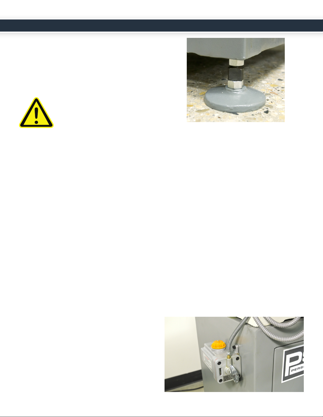
7. Thread the stud, nut, and washer onto the machine
foot and screw the machine foot assembly into
the boom of the grinder cabinet as shown in the
following photo.
8. Slowly lower the machine to the ground at its desired
locaon and replace the table and table ags.
9. Level the machine, adjusng the posion of each
machine foot assembly as necessary.
PROTECTING FROM RUST
Exposed iron and steel surfaces should always be protected
from rust and corrosive environments. If your grinder will
be unused for more than a couple days, you should mist
the surfaces with light water repellent oil such as WD-40.
INITIAL LUBRICATION
The X-axis has a bonded layer of plasc compound, a
composion of Acetyl and PTFE similar to Turcite®. This
is state of the art technology for oil lubricated slideways
and superior to plain ground surfaces or hardened and
chromed surfaces.
When properly maintained, sliding surfaces will last for a
long me. If you use the oil lubricaon system properly the
slideways are not normally maintenance items.
The central lubricaon pump should be lled with quality
way oil. We recommend Perkins Perlube WL-68 (Tormach
Part Number 31386). Other acceptable alternaves
are Tonna 68 (Shell), Vactra No. 2 (Mobil), Way-lube
68 (Sunoco), WayLube 68 (Texaco), Febis 68 (Esso) or
equivalent oil.
INSTALLATION
UM10159_PSG612_OPERATORS_MANUAL_0718A 89UM10159_PSG612_OPERATORS_MANUAL_0718A

A shot of lubricaon should be given for each 4 hours of
operaon and aer the machine has stood unused for
more than 48 hours.
Always make certain that the lubricaon oil is clean. The
oil is delivered to 7 points throughout the machine. This
includes (reference the Lubricaon Schemac on the next
page):
• X-Front
• X-Back
• Y-Right
• Y-Le
• X-Drive Sha
• Z-Ways
• Y-Leadscrew
These are some of the most crical and expensive
mechanical parts of the machine. Any dirt or foreign
material suspended in the oil is going to be delivered
directly to these parts and can dramacally shorten the
eecve life of the machine.
Be sure to clean o the cover and surrounding area before
relling the oil reservoir. The strainer at the top of the
reservoir is only a screen; it is not a lter.
Your PSG 612 comes standard with a single shot manual
oil pump. An oponal Automac Oiler is also available
(Tormach Part Number 31373).
Notes:
• The pump is spring loaded, where the spring
force creates a very light hydraulic pressure. You
can get the oil out quicker by pushing a bit, but
apply too much force and you can pop o one of
the oil lines.
• You will have a more uniform distribuon of oil
if the machine is moving when the hydraulic
pressure is applied.
• The pump sucks up oil from the reservoir on the
pull stroke and delivers it to the machine on the
push stroke. If at some point the oil pump seems
to move much easier on the push stroke then
make certain that you do not have a broken oil
line.
• Extreme axis posions can expose the oil
distribuon channels that are cut into the way
support saddle surfaces. If the pump is used in
those posions the hydraulic force of the oil will
not apply it throughout the machine as intended.
Instead the oil will simply squirt out at the point
where the oil channel is exposed.
• Aer a long period of inacvity or in cold
condions the oil system may become clogged.
See Tormach Service Bullen SB0031 – Flushing
the Lubricaon System in the Event of a Clog.
UM10159_PSG612_OPERATORS_MANUAL_0718A 89UM10159_PSG612_OPERATORS_MANUAL_0718A

P-18
P-19
P-20
P-21
Elbow (31311)
Nut (31310)
Ferrule (31309)
Manifold Orifice (31370)
Gib Orifice (31408)
Nut and Ferrule Bundle (31409)
4mm Nylon Tubing (31304)
PUMP
(31302 or 31373)
Left Side
Y Lead
Screw
X Front
Y Right
Y Left
X Drive
Short
Z Ways
Protective Metal Sheath (31306)
Compression Fittings
Large XY
manifold
(34709)
X Back
P-1
P-2
P-3
P-4
(33954)
UM10159_PSG612_OPERATORS_MANUAL_0718A 10 11 UM10159_PSG612_OPERATORS_MANUAL_0718A

CONTROL MODES AND POWER
CONTROLS
Speed and Feed
The speed and feed knobs are used to control the moon
of the work table. Speed controls X-axis moon and Feed
controls how far the table moves in the Y-axis. Turn the
knobs in a clockwise direcon to increase speed or feed.
Wheel On/Wheel Off
The Wheel On and Wheel O buons turn the grinding
wheel on and o, respecvely. Wheel O will not stop the
X- or Y-axis.
1. Mode Select Button
Push this buon to switch between grinding modes. Each mode
has a green LED below the mode symbol to indicate the mode is
acve. The machine will not change feed modes while in moon.
2. Feed at Both Ends The grinder feeds in the Y-axis at each end of the X-axis stroke.
3. Feed at Left End Only The grinder feeds in the Y-axis at the le end of each X-axis stroke.
4. Continuous Feed The Y-axis is in connuous feed at set feed.
5. No Feed Use this feed for plunge grinding. No Y-axis moon.
Start/Stop
The Start/Stop buon starts and stops table moon.
E-Stop
The E-Stop buon supplies power to the machine. Rotate
to power up
Main Power Disconnect
The Power Mains switch (located on the side of the control
panel) completely disconnects the machine from an
electrical power source.
Speed
Feed
GRINDER OPERATION
UM10159_PSG612_OPERATORS_MANUAL_0718A 10 11 UM10159_PSG612_OPERATORS_MANUAL_0718A
POWERING UP THE MACHINE
1. Connect the main power cord to an approved IEC wall
outlet.
2. Turn the main disconnect located on the side of the
cabinet to on.
3. Rotate the red emergency (E-stop) knob located on the
electrical box.
4. All of the LED lights on the control panel will blink
once, indicang power to the machine.
5. If either of the LED lights for the speed or feed buon
is acve (red), the table is outside the dened range of
moon and the table is tripping a proximity switch.
6. Manually adjust the table in the X- or Y- direcon if
necessary. The table should move freely.
7. When the table locaon is within the limits, the red
LED lights will turn o.
8. Select the desired grinder operaon mode by pushing
the Mode Select buon unl the LED light to that
operaon turns green.
9. Press/toggle the black start buon to start and stop
table moon. The E-Stop buon should be used in
emergency situaons and to completely terminate
power to the machine.
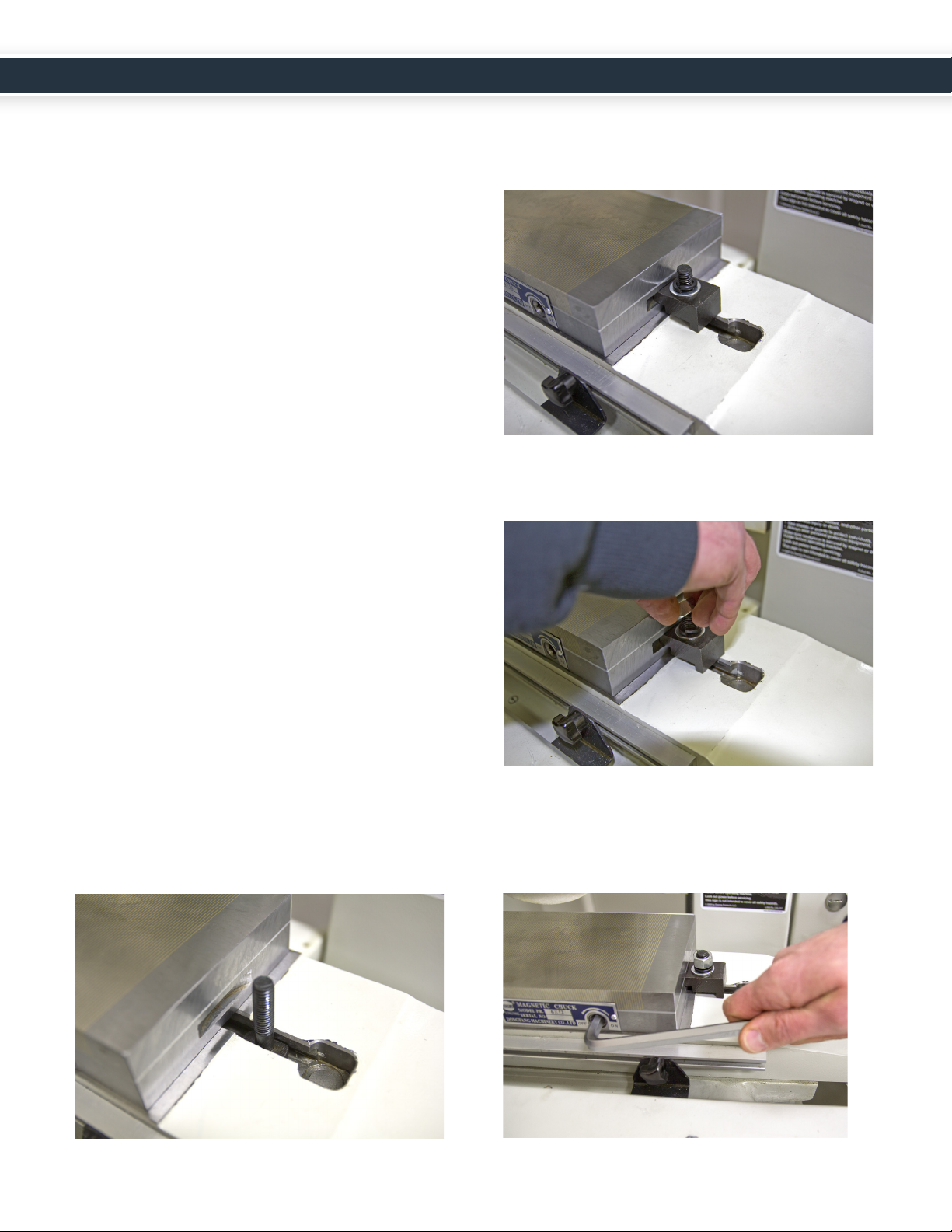
USING THE MAGNETIC CHUCK
To install the Magnec Chuck (Tormach Part Number
33210) for workholding:
1. Locate the auxiliary clamps with bolts and nuts
(included in the tool box).
2. Wipe the table surface clean, removing any debris or
material.
3. Place the magnec chuck on the grinding surface.
4. Insert the bolts in the T-slots located on either side of
the magnec chuck.
5. Lower the clamps down onto the bolts and then
slide the xture into the grooves on each side of the
magnec chuck.
6. Slide the washer and nut down onto the top of the
bolts and ghten.
7. Insert the wrench into the slot on the front face of the
magnec chuck. Rotate the wrench to the direcon
of “on” or “o” to acvate or deacvate the magnec
eld.
UM10159_PSG612_OPERATORS_MANUAL_0718A 12 13 UM10159_PSG612_OPERATORS_MANUAL_0718A

ADJUSTING TABLE FLAGS
Adjust the distance between the X-axis and Y-axis table
ags to the size of the part being ground.
To set the X-axis and Y-axis travel limits, move the table
ags to the desired locaon by loosening and sliding the
thumbscrews.
Note: Dierent table speeds will produce dierent
amounts of overtravel. As an example, with slow
table movement the table will stop quicker in a
smaller distance than when the table speed is faster.
You may need to adjust the table ags if you change
your table speed.
Note: The thumbscrews must remain on opposite
sides of the proximity switch located in the center
of the grinding surface under the table guard. If
both screws (table ags) are moved to either side
of the proximity switch, the table will not run. If the
proximity switch is defecve, the LEDs will not light.
Keep the travel flags on opposite sides of the
proximity switch located under the table guard.
INSTALLING A GRINDING WHEEL
CAUTION: NEVER INSTALL A
GRINDING WHEEL THAT HAS NOT
BEEN PROPERLY BALANCED.
There are many reasons for changing the grinding wheel.
These include changing the type of material that is being
ground or changing the grit type of the wheel itself (for
example, from ne to course). Over me the grinding
wheel will experience wear and will need to be replaced.
1. Remove the three socket head cap screws that hold
the wheel guard cover.
2. Set the wheel guard cover to the side.
3. Using the spanner wrench, remove the spindle nut.
Note: The spindle nut is a le-hand thread.
WORKING WITH WHEELS
UM10159_PSG612_OPERATORS_MANUAL_0718A 12 13 UM10159_PSG612_OPERATORS_MANUAL_0718A

4. Firmly grasp the grinding wheel with one hand and
remove the hub. If the wheel spins freely, you will
need to hold the wheel in one hand while you insert
the spindle wrench in the slot on the back side of the
spindle motor.
Note: You may need to lightly tap the hub in order to
remove the tapered hub from the spindle sha.
5. Pull the hub and wheel back and away from the
grinder.
6. Ensure the inside of the hub is clean and free from
debris. A clean nger works best for this job.
7. Also ensure the spindle taper is wiped clean.
8. Gently place the new wheel onto the spindle and
install the nut, keeping in mind it is a le-hand thread.
9. Hold the wheel in one hand and ghten it down with a
spanner wrench.
Note: You may need to re-insert the spindle wrench
in the slot on the back side of the spindle motor. Do
not over ghten.
10. Replace the cover and the socket head cap screws.
RING TEST
Lightly tap the circumference of the grinding wheel with
a metal object (a wrench works ne). Listen for consistent
ringing sounds. There should be no dead tones as you tap
in several locaons around the wheel.
CAUTION: THE GRINDING WHEEL
SHOULD BE PROPERLY BALANCED
AND DRESSED BEFORE FIRST USE.
UM10159_PSG612_OPERATORS_MANUAL_0718A 14 15 UM10159_PSG612_OPERATORS_MANUAL_0718A
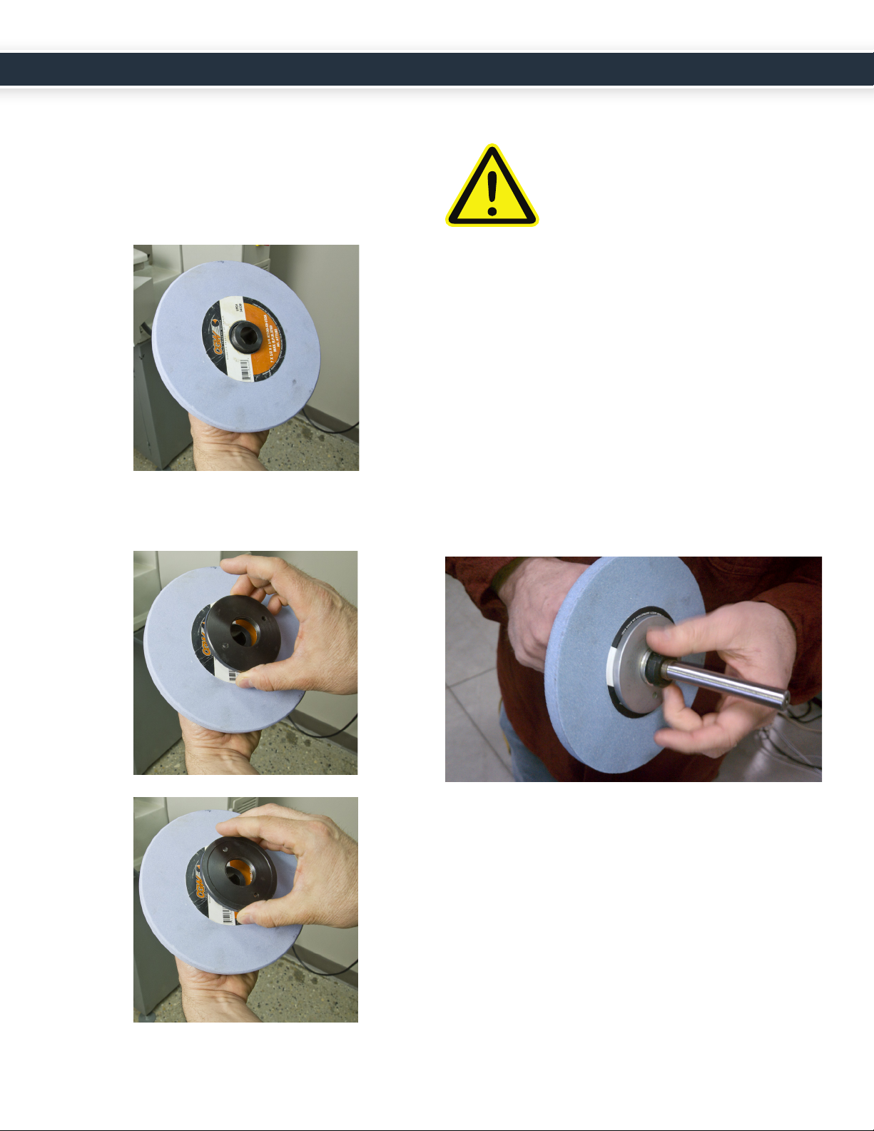
REPLACING THE HUB ON A
GRINDING WHEEL
1. Insert the wheel onto the hub with the product label
facing out/up so that the wheel is resng at against
the back shoulder of the hub.
2. While holding the back of the hub, screw the nut onto
the hub (again note the le handed threads). Make
sure that the “ledge” side of the hub is facing the
wheel.
Correct
Incorrect
3. Tighten the hub nut using the spanner wrench.
CAUTION: OVER TIGHTENING THE
HUB NUT CAN DAMAGE THE
GRINDING WHEEL.
WHEEL BALANCING
For more informaon on balancing a wheel, go to
tormach.com/support and watch our video, Surface
Grinder Basics: How to Balance a Grinding Wheel.
To eliminate vibraon of the grinding wheel during
normal operaon, the grinding weight should be properly
balanced on the wheel hub.
1. To adjust the balance, remove the wheel and hub from
the grinder.
2. Thread the wheel hub onto the balancing arbor and
secure it in place with the washer and nut included
with the accessory kit.
3. Using a level surface and two equally sized resng
blocks (1-2-3 blocks work ne for this task), rest the
balancing arbor on the plates with the wheel between
the plates as shown.
UM10159_PSG612_OPERATORS_MANUAL_0718A 14 15 UM10159_PSG612_OPERATORS_MANUAL_0718A
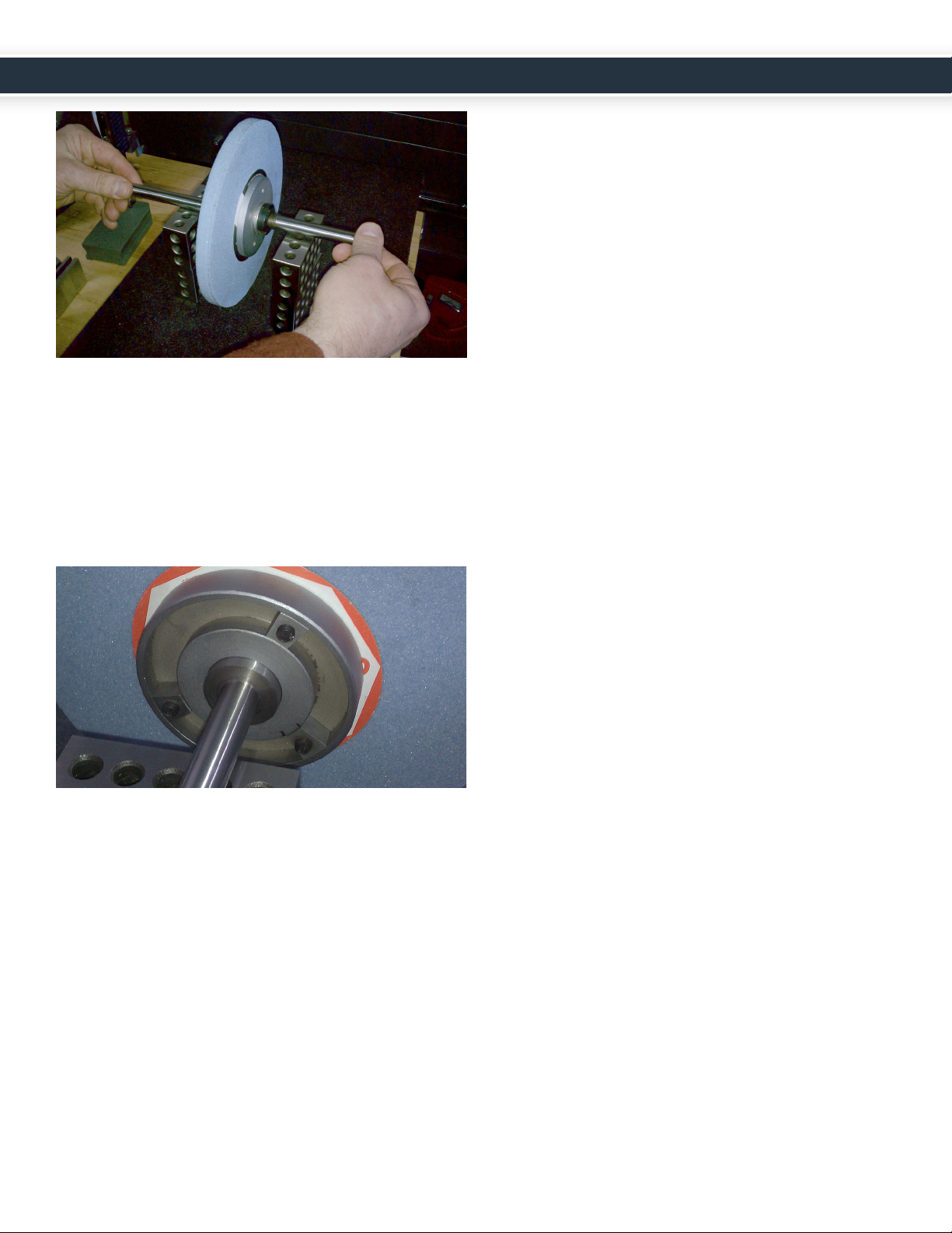
4. Spin the arbor in either direcon and set it on the
blocks as show in the above photo. When you let go
of the arbor, the wheel should remain at rest. If the
wheel is not balanced, it will rotate. Repeat this step
several mes.
5. If necessary, adjust the balancing weights on the inside
side of the wheel hub using a at head screwdriver,
moving the weights away from the direcon of the
“heavy spot.”
DRESSING A WHEEL
For more informaon on dressing a wheel, go to
tormach.com/support and watch our video, Surface
Grinder Basics: Grinding Wheel Dressing with an Opcal
Wheel Dresser.
1. When facing the machine, place the wheel dresser
onto the surface grinder magnet with the pointed
diamond p on center.
2. Turn the grinding wheel on in staonary moon and
turn the feed and speed knobs full to the le (in the o
posion) to eliminate table moon.
3. Carefully feed the grinding wheel down onto the
diamond using the vercal adjustment handwheel
(Z-axis downfeed) unl contact is made between the
p and the grinding wheel surface.
4. Turn the table jog handwheel (Y-axis crossfeed) and
slowly move the diamond p across wheel surface and
dress unl the wheel achieves the desired nish.
Note: Reference the Control Modes secon for a
denion of the control modes and instrucons on
switching between modes of operaon.
UM10159_PSG612_OPERATORS_MANUAL_0718A 16 17 UM10159_PSG612_OPERATORS_MANUAL_0718A

BACKLASH ADJUSTMENT
Over the course of normal operaon, the PSG 612 may
need backlash adjustment on the Y-axis crossfeed and
(less frequently) on the Z-axis downfeed. If you noce
lost moon in Y- or Z- adjust the backlash adjustment set
screws as follows:
1. Manually move the table in the Y- or Z- direcon so
that it reaches the edge of travel.
2. Using an Allen wrench, manually ghten both set
screws, ensuring the screws are ghtened evenly.
Note: The set screws are located to the le and the
right of the lead screw as shown:
Set Screw Adjustment on the Y-Axis
Set Screw Adjustment on the Z-Axis
GIB SCREW ADJUSTMENT
The slide ways are hand scraped as part of the
manufacturing process. This means that the Z axis saddle
is ed to the column. They are scraped in as a set
and neither the saddle nor the column can be had as a
replacement component. Likewise, the base, XY saddle,
and machine table are scraped in as a set.
The slide ways have tapered gib plates (also hand scraped),
where the posion of the Gib Plate controls the ghtness
and fricon in a slide way.
Like the backlash adjustment on lead screws, the gib
screws on the Y- and Z-axes can loosen over the course of
normal operaon.
1. If you noce the table is wobbling, manually ghten
the gib screw with a at head screwdriver unl you
feel resistance as you move the axis.
2. Back o 1/8 turn.
Note: You may want to manually ghten the gib
screws before rst use, as the grinder may have
experienced excess vibraon during transit.
CHANGING/CLEANING AIR
FILTERS
1. Remove the enre air lter panel from the side of the
control panel.
2. Using a screwdriver, open the front panel cover and
remove the air lter.
MACHINE MAINTENANCE
UM10159_PSG612_OPERATORS_MANUAL_0718A 16 17 UM10159_PSG612_OPERATORS_MANUAL_0718A

3. Wash the air lter with mild soapy water and air dry.
Reassemble the panel and place it into posion on the
control panel.
REPLACING FUSE
Note: While 32A is the fuse holder rang, the Tor-
mach PSG612 is rated for a 15A fuse. Replacement
fuses should be 15A.
WARNING: UNPLUG THE MACHINE
BEFORE REPLACING FUSE.
1. Pull down on the tab at the top of the fuse box.
2. Open the housing and carefully pull the fuse out
of the box.
3. Insert a replacement 15A fuse.
REPLACING THE YAXIS BELT
1. Remove the two cover guard screws.
2. Li and remove the cover guard.
3. Move the table fully to the le.
4. Remove the ve motor cover screws.
UM10159_PSG612_OPERATORS_MANUAL_0718A 18 19 UM10159_PSG612_OPERATORS_MANUAL_0718A
Table of contents
Popular Grinder manuals by other brands


Hitachi
Hitachi G 18SH2 Technical data and service manual

EINHELL
EINHELL TC-AG 115/1 Original operating instructions

Chicago Pneumatic
Chicago Pneumatic RediPower RP9105QB Operator's manual

Makita
Makita DGA508RFE instruction manual

Ingersoll-Rand
Ingersoll-Rand AG Series Product information

Makita
Makita 9005B instruction manual