Tormach PCNC 1100 User manual

Questions or comments?
All rights reserved.
UM10349_PCNC1100_Manual_0916A
Document Part Number: 35426
©2015 Tormach Inc.
IMPORTANT: Read and understand all operator manual safety precautions and instructions
before attempting PCNC 1100 installation, operation, or maintenance.
Tormach®PCNC
1100
Operator Manual
™

Chapter 1 2UM10349_PCNC1100_Manual_0916A
Preface
SAVE THESE INSTRUCTIONS!
This manual contains important safety warnings and operang instrucons for the Tormach PCNC
1100 mill. Refer to these instrucons before aempng installaon, operaon or maintenance.
Keep these instrucons together with your PCNC 1100 mill so they are readily accessible. The most
recent version of this manual is available at: www.tormach.com/tormach_product_manuals
Read Before Operating
Read and follow all warnings, cauons, and operang instrucons before operang this mill. Failure
to do so may result in voided warranty, property damage, serious injury or death.
Symbol Description Example
WARNING! Indicates a hazard which, if not
avoided, could result in death or serious injury.
WARNING! Ejection Hazard: Tools and
workpieces must be clamped properly. Failure to do
so may result in serious injury or death.
CAUTION! Indicates a hazard which, if not
avoided, could result in injury or mill damage.
CAUTION! Sharp Objects: Be sure to wear
gloves when uncrating mill. Failure to do so may
result in serious injury.
IMPORTANT! IMPORTANT! Addresses important practices not
related to personal injury.
IMPORTANT! Damage to mill may occur if
motor weight is supported by motor wires.
NOTE: NOTE:Provides additional information, clarication,
reminders, or helpful hints.
NOTE: For further information on automatic oiler
troubleshooting, refer to operator manual.
Safety Overview
Any machine tool is potenally dangerous. The automaon inherent in a CNC machine presents
added risk not present in a manual mill. Tormach CNC mills can deliver sucient force to break
brile tools, crush bones, and tear esh.
This manual provides guidance on safety precauons and techniques, but because the specics of
any one workshop (or other local condions) can vary greatly, Tormach accepts no responsibility for
machine performance or any damage or injury caused by its use. It is your responsibility to ensure
you understand the implicaons of what you are doing and comply with any legislaon and codes
of pracce applicable to your city, state or naon.

Chapter 1
3
UM10349_PCNC1100_Manual_0916A
Preface
Machine Safety
Safe operaon of the machine depends on its proper use and the precauons taken by the operator.
Read and understand this manual prior to mill use. Only trained personnel — with a clear and
thorough understanding of its operaon and safety requirements — should operate this mill.
General Safety:
• Wear OSHA-approved safety glasses, safety shoes, and ear protecon.
• Remove loose-ng clothing, neckes, gloves, and jewelry.
• Tie up long hair or secure under a hat.
• Never operate a machine aer consuming alcohol or taking medicaon.
• Keep work area well lit and deploy addional lighng, if needed.
Operaonal Safety:
• Understand CNC mills are automacally controlled and may start at any me.
• Never operate with unbalanced tooling or spindle xtures.
• Remove all tools (wrenches, chuck keys, etc.) from spindle and machine table before starng
operaons; loose items can become dangerous projecles.
• Use adequate work clamping; loose workpieces can become dangerous projecles.
• Protect your hands. Stop machine spindle and ensure mill moon has stopped before:
- Reaching into any part of the machine moon envelope
- Changing tools, parts or adjusng the workpiece
- Changing belt/pulley posion
- Clearing away chips, oil or coolant; always use a chip scraper or brush
- Making an adjustment to part, xture, coolant nozzle or when taking measurements
- Removing protecve shields or safeguards; never reach around a guard
• Keep work area clear of cluer as mill moon can occur when keys are accidently pressed or
objects fall on keyboard, resulng in unexpected moon.
• Posion clamping aachments clear of tool path. Be aware of workpiece cutos that could be
cut free during operaons and become dangerous projecles.
• Always use proper feeds/speeds, as well as depth/width of cut to prevent tool breakage.
• Check for damaged tools/workpieces and cease operaons if detected; replace before
restarng operaons as these can become dangerous projecles. Never use longer or larger
tools than necessary.

Chapter 1 4UM10349_PCNC1100_Manual_0916A
Preface
• Chips and dust from certain materials (e.g., magnesium) can be ammable. Fine dust from
normally non-ammable materials may be ammable or even explosive.
• Chips, dust, and vapors from certain materials can be toxic. Always check the Materials Safety
Data Sheet (MSDS) for each material.
IMPORTANT: It is the responsibility of the employer/operator to provide and ensure point of operaon
safeguarding per the following:
• OSHA 1910.212 – General Requirements for All Machines
• OSHA 1910.212 – Milling Machines, point of operaon safeguarding
• ANSI B11.22-2002 Safety Requirements for Turning Centers and Automac Numerically
Controlled Turning Machines
• ANSI B11.TR3-2000 Risk Assessment and Risk Reducon – A Guideline to Esmate, Evaluate,
and Reduce Risks Associated with Machine Tools
• Safety Requirements for Construcon, Care, and Use of Drilling, Milling and Boring Machines
(ANSI B11.8-1983). Available from American Naonal Standards Instute, 1430 Broadway,
New York, New York 10018
• Concepts and Techniques of Machine Safeguarding (OSHA Publicaon Number 3067).
Available from The Publicaon Oce – OSHA, U.S. Department of Labor, 200 Constuon
Avenue, NW, Washington, DC 20210
Electrical Safety
WARNING! Electrical Shock Hazard: Be sure to power o machine before making any electrical
modicaons. Failure to do so may result in serious injury or death.
Input Power: The PCNC 1100 has two electrical power inputs, primary and secondary. The 230 VAC
primary input supplies axis and spindle power, while the 115 VAC secondary input supplies power
to the PathPilot®controller and accessory outlets. The wiring and electrical components associated
with either circuit are capable of delivering lethal electrical shocks. Care should be exercised when
working inside the electrical cabinet.
Grounding: Both primary and secondary power inputs must be grounded. Do not assume during
installaon that a wall outlet is properly grounded. Check connuity between the machine frame
and true earth ground (metal water pipe or similar) to ensure a good ground connecon.
Ground Fault Interrupter: A Ground Fault Interrupter or GFI (also known as a Residual Current
Circuit Breaker or RCCB) outlet must be used to supply power to the 115 VAC power input for the
secondary input.

Chapter 1
5
UM10349_PCNC1100_Manual_0916A
Preface
Electrical Cabinet: Never operate the machine tool with the electrical cabinet open. Never allow
coolant pump to operate with the electrical cabinet open. Do not allow the coolant system to ow
coolant directly at the electrical cabinet or the operator panel. Neither the electrical cabinet nor the
operator panel controls are hermecally sealed against liquids.
Electrical Service: Certain service and troubleshoong operaons require access to the electrical
cabinet while power is on. Only qualied electrical technicians should perform such operaons.
Retained Electrical Power: Electronic devices within the electrical cabinet may retain dangerous
electrical voltage aer the power is o.
Support
Tormach provides no-cost technical support to our customers through mulple channels. The
quickest way to get the answers you need is normally in this order:
• Refer to operator manual rst
• Reference related documents at: hp://www.tormach.com/documents
• Email: inf[email protected]
• Phone: 608-849-8381 x2001, Monday through Friday 8 a.m. to 5 p.m. (central standard me)
• Fax: 209-885-4534
Scope and Intellectual Property
This document is intended to provide sucient informaon to allow you to install, setup, and use
your Tormach PCNC mill. It assumes that you have appropriate experience and/or access to training
for any computer-aided design/manufacturing soware to use with the mill.
Tormach Inc. is dedicated to connual improvement of its products, so suggesons for enhancements,
correcons, and claricaons are welcome.
The right to make copies of this manual is granted solely for the purpose of training courses related
to, evaluaon of, and/or use of the mill. It is not permied, under this right, for third pares to
charge for copies beyond the cost of prinng.
Every eort has been made to make this manual as complete and as accurate as possible but no
warranty or tness is claimed or implied. All informaon provided is on an as is basis. The authors,
publisher, and Tormach Inc. shall not have any liability for, or responsibility to, any person or enty
for any reason for any loss or damage arising from the informaon contained in this manual.
Tormach, PCNC 1100 Personal CNC, PCNC 770 Personal CNC, Tormach Tooling System (TTS), and
PathPilot are trademarks or registered trademarks of Tormach Inc. If other trademarks are used
in this manual, but not acknowledged, please nofy Tormach Inc. so this can be remedied in
subsequent edions. Tormach milling machines and accessories are covered by one or more of the
following U.S. Patents: 7,386,362, D606,568, D612,406, D621,859 and Patent(s) Pending.

Chapter 1 6UM10349_PCNC1100_Manual_0916A
Preface
Intended Use Statement
The PCNC 1100 is intended for use as a general purpose CNC milling machine. The intended use includes
cung convenonal (non-abrasive) materials such as unhardened mild or alloy steels, aluminum,
plascs, wood, and similar materials (or other material that can be cut with a rotang cuer).
Outside Scope of Intended Use
Applicaons for the equipment or modicaons of the equipment outside of the Intended Use
Statement are supported through consulng engineering and excluded from Tormach’s no-cost
technical support.
All of the technical informaon and insight required to support variaons from the intended use
cannot possibly be foreseen. If the extensive documentaon provided is insucient, Tormach can
provide addional informaon and engineering support on a consulng-engineering basis. If you
have your quesons well organized, we can normally provide all the informaon you need in short
order. Consulng engineering is done by electrical and mechanical engineers and billed at current
hourly rates.
All warranes for Tormach equipment are voided through modicaon to the equipment or use
outside of the intended use. Individuals or companies involved with modifying the equipment or
applying the products assume all consequent liability.
Performance Expectations and Cutting Ability
The following table summarizes the cung performance envelope of each PCNC mill.
PCNC 1100 PCNC 770
Spindle Speed Range1100-5140 RPM 175-10000 RPM
Spindle Power Rating 1.5 hp 1 hp
Feed Rate Range 0-110 ipm (X,Y)
0-90 ipm (Z)
0-135 ipm (X,Y)
0-110 ipm (Z)
1For standard R8 spindle
PCNC mills are capable of cung any material that can be cut with a rotang cuer at or near their
recommended feeds and speeds. As with any mill, care should be exercised so that programmed
cuts do not exceed the maximum available spindle horsepower. Small diameter cuers may perform
beer with use of a companion spindle or RPM mulplier such as the Tormach Speeder™ (for more
informaon, refer to chapter 8, Accessories).

Chapter 1
7
UM10349_PCNC1100_Manual_0916A
Preface
Resolution, Accuracy, and Repeatability
The following table summarizes resoluon, accuracy, and repeatability of PCNC mills as delivered.
Resolution of Motion (minimum discrete positional move) 0.0001”
Ball Screw Positional Accuracy ≤ 0.0006” per foot
Combined Positional Accuracy1≤ 0.0013” per foot
1 Includes addional contribung factors such as compressibility of bearings, ball screw windup, fricon, etc.
Each PCNC Mill ships with a Cercate of Inspecon. This report details quality assurance
measurements performed at the factory by a Tormach quality assurance team member on each mill
prior to shipping.
A sample cercate of inspecon and more informaon on quality assurance measurements is
available at: hp://www.tormach.com/quality_overview.html
In pracce, accuracy and repeatability are heavily inuenced by the techniques used by the
machinist. A skilled machinist can oen deliver accuracy that exceeds the accuracy specied by
the manufacturer, while an inexperienced machinist may have diculty delivering the expected
accuracy. With this understanding, Tormach cannot predict operator accuracy. Nevertheless, the
accuracy specied by the manufacturer remains an important reference point.
Nomenclature
This manual uses the following typographical nomenclature.
Soware Control Refers to a Software Control, i.e., an on-screen button
Hardware Control Refers to a button or switch on mill’s Operator Panel
G-code (e.g., G01X34.8) Used to show G-code programs
Key name (i.e., Enter)Tells you to press the indicated key
Buon name (i.e., Stop)Tells you to press the indicated button

Chapter 1 8UM10349_PCNC1100_Manual_0916A
Preface
Table of Contents
1. Overview 20
1.1 Specicaons (PCNC 1100) 21
2. Site Planning and Prep 22
2.1 General Site Requirements 22
2.1.1 Space Requirements 22
2.2 Electrical Requirements 22
2.2.1 Grounding 22
2.2.2 Plug Paern 22
2.2.3 Ground Fault Interrupter (GFI) Use 23
2.2.4 Electrical Noise 23
2.2.5 Opons for Electrically Non-conforming Sites 23
2.2.5.1 Buck-Boost Transformer 23
2.2.5.2 Step-up/Step-down Transformer 23
2.2.5.3 Quick 220™ Voltage Converter Power Supply 23
3. Installaon 24
3.1 Receiving, Uncrang, and Inial Inspecon 24
3.1.1 Shipment Arrival 24
3.1.2 Moving the Crate 24
3.1.3 Inial Uncrang 25
3.1.4 Shipping Damage or Shortages 25
3.2 Installaon Sequence 25
3.3 Basic Installaon Procedure 25
3.3.1 Paral Stand Assembly 25
3.3.2 Remove Tool Tray (PCNC 1100 only) 26
3.3.3 Remove Accessory Tool Box 26
3.3.4 Assembling Y-Axis (PCNC 1100 only) 26

Chapter 1
9
UM10349_PCNC1100_Manual_0916A
Preface
3.3.5 Li and Move Mill 27
3.3.5.1 Remove Mill from Pallet 27
3.3.5.2 Liing Bar Kit 27
3.3.5.3 Liing from Below 27
3.3.5.4 Moving Kit (PCNC 770 Only) 28
3.3.5.5 Lowering Mill onto Stand 28
3.3.6 Install Tool Tray (PCNC 1100 only) 28
3.3.7 Install Drip Tray 28
3.3.8 Install PathPilot Controller 29
3.4 Installaon of Add-ons 31
3.4.1 Stand 31
3.4.2 Machine Arm 31
3.4.2.1 Mouse, Keyboard, and Jog Shule 31
3.4.3 USB Bulkhead Port 31
3.4.4 Manual or Automac Oiler 31
3.4.5 Coolant System 31
3.5 Essenal Controls Overview 32
3.5.1 E-stop, Start, Reset, and Power 32
3.6 Power O/Power On Procedure 33
3.6.1 Inial PathPilot Controller Conguraon 34
3.7 Validate Basic Installaon 34
3.7.1 Verify Spindle Funcon 34
3.7.2 Verify Limit Switch Funcon 35
3.7.3 Verify Axis Funcon 36
3.7.4 Coolant On/O 36
3.7.5 Installaon Troubleshoong 36
3.8 Controller Customizaon 37

Chapter 1 10 UM10349_PCNC1100_Manual_0916A
Preface
4. Operaon 38
4.1 Control Locaons 38
4.1.1 Operator Panel 38
4.1.2 PathPilot Interface 38
4.2 Inializing the Mill 39
4.2.1 Vital Reference 39
4.3 Jogging 39
4.3.1 Manual Control Group 39
4.4 Spindle Controls 40
4.4.1 Manual Spindle Control Via Operator Panel 40
4.4.2 Automated Spindle Control Via PathPilot Interface 41
4.4.3 Changing Spindle Speed Range 41
4.5 Tool Holders 42
4.6 Part Setup/Workholding 43
5. Intro to PathPilot 44
5.1 Making Your First Part 44
5.1.1 Referencing the Mill 44
5.1.2 Workpiece Preparaon 45
5.1.3 Tooling Preparaon 45
5.1.4 Mill Posion, Work Osets and Tool Osets 45
5.1.4.1 Seng Work Oset by Touching O Workpiece 46
5.1.4.2 Seng Tool Length Oset by Touching O Workpiece 48
5.1.5 Wring the G-code 49
5.1.5.1 Operaon 1 49
5.1.5.2 Operaon 2 51
6. PathPilot Interface 53
6.1 Overall Layout 53
6.2 Persistent Controls 54

Chapter 1
11
UM10349_PCNC1100_Manual_0916A
Preface
6.2.1 Program Control Group 54
6.2.2 Posion Status Group 56
6.2.3 Manual Control Group 57
6.2.4 Keyboard Shortcuts 60
6.3 Main Tab 60
6.4 File Tab 64
6.5 Sengs Tab 65
6.6 Osets Tab 68
6.6.1 Tool Tab 68
6.6.1.1 Oine Measurement with Height Gauge 69
6.6.1.2 Automated Measurement with an Electronic Tool Seer 69
6.6.1.3 Measurement by Touching O Tool 70
6.6.2 Osets Table 70
6.6.3 Tool Oset and Fixture Informaon Backup 70
6.6.4 Work Tab 70
6.7 Conversaonal Tab 71
6.7.1 Face Tab 71
6.7.2 Prole Tab 72
6.7.3 Pocket Tab 73
6.7.3.1 Rectangular 73
6.7.3.2 Circular 75
6.7.4 Drill/Tap Tab 76
6.7.4.1 Drill 78
6.7.4.2 Tap 79
6.7.5 Thread Mill Tab 80
6.7.6 Engrave Tab 82
6.8 Probe Tab 84

Chapter 1 12 UM10349_PCNC1100_Manual_0916A
Preface
6.8.1 XYZ Probe Tab 84
6.8.2 Rect/Circ Tab 85
6.8.3 Probe/ETS Setup Tab 86
6.9 ADMIN Commands 86
7. Programming 87
7.1 Denions 87
7.2 G-code Programming Language 90
7.2.1 Overview 90
7.2.2 Block 90
7.2.3 Real Value 90
7.2.4 Number 90
7.3 Formang G-code Blocks 91
7.3.1 Oponal Program Stop Control – (M01 BREAK) 94
7.4 Addional G-code Formang Notes 94
7.4.1 Repeated Items 94
7.4.2 Order of Execuon 94
7.4.3 Error Handling 96
7.4.4 Modality and Modal Commands 96
7.4.5 Modal Groups 96
7.4.6 Default Modes 97
7.5 G-codes 97
7.5.1 Rapid Linear Moon – G00 99
7.5.2 Linear Moon at Feed Rate – G01 100
7.5.3 Arc at Feed Rate – G02 and G03 101
7.5.3.1 Radius Format Arc 101
7.5.3.2 Center Format Arc 102
7.5.4 Dwell – G04 105

Chapter 1
13
UM10349_PCNC1100_Manual_0916A
Preface
7.5.5 Set Osets – G10 105
7.5.5.1 Set Tool Table – G10 L1 105
7.5.5.2 Set Coordinate System – G10 L2 106
7.5.5.3 Set Tool Table – G10 L10 106
7.5.5.4 Set Tool Table – G10 L11 107
7.5.5.5 Set Coordinate System – G10 L20 107
7.5.6 Plane Selecon – G17, G18 and G19 108
7.5.7 Length Units – G20 and G21 108
7.5.8 Return to Pre-dened Posion – G28 and G28.1 108
7.5.9 Return to Pre-dened Posion – G30 and G30.1 109
7.5.10 Straight Probe – G38.x 109
7.5.10.1 Using the Straight Probe Command 110
7.5.11 Cuer Compensaon 111
7.5.12 Dynamic Cuer Compensaon – G41.1, G42.1 112
7.5.13 Apply Tool Length Oset – G43 112
7.5.14 Engrave Sequenal Serial Number – G47 113
7.5.15 G49 Cancel Tool Length Compensaon – G49 113
7.5.16 Absolute Coordinates – G53 114
7.5.17 Select Work Oset Coordinate System – G54 to G59.3 114
7.5.18 Set Exact Path Control Mode – G61 114
7.5.19 Set Blended Path Control Mode – G64 115
7.6 Canned Cycles 115
7.6.1 Preliminary Canned Cycle Moon 117
7.6.2 Canned Cycle – High Speed Peck Drill – G73 117
7.6.2.1 G80 Cycle 118
7.6.2.2 G81 Cycle 118
7.6.2.3 G82 Cycle 120

Chapter 1 14 UM10349_PCNC1100_Manual_0916A
Preface
7.6.2.4 G83 Cycle 121
7.6.2.5 G85 Cycle – Boring Cycle (Feed rate out) 121
7.6.2.6 G88 Cycle – Boring Cycle (Dwell, Manual Out) 122
7.6.2.7 G89 Cycle – Boring Cycle (Dwell, Feed rate out) 122
7.6.2.8 Distance Mode – G90 and G91 123
7.6.2.9 Arc Distance Mode – G90.1, G91.1 123
7.6.2.10 Temporary Work Osets – G92, G92.1, G92.2 and G92.3 123
7.6.2.11 Feed Rate Mode – G93, G94 and G95 124
7.6.2.12 Spindle Control Mode – G96, G97 125
7.7 Built-in M-codes 125
7.7.1 Program Stop and Program End – M00, M01, M02 and M30 126
7.7.2 Spindle Control – M03, M04 and M05 127
7.7.3 Tool Change – M06 127
7.7.4 Coolant Control – M07, M08 and M09 127
7.7.5 Override Control – M48 and M49 128
7.7.6 Feed Override Control – M50 128
7.7.7 Spindle Speed Override Control – M51 128
7.7.8 Set Current Tool Number – M61 128
7.7.9 Set Output State – M64/M65 128
7.7.10 Wait on Input – M66 130
7.7.11 Operator Dened Commands – M100 to M199 130
7.8 Other Input Codes 131
7.8.1 Feed Rate – F 131
7.8.2 Spindle Speed – S 131
7.8.3 Change Tool Number – T 131
7.9 Advanced Programming with Parameters and Expressions 131
7.9.1 Parameters 131

Chapter 1
15
UM10349_PCNC1100_Manual_0916A
Preface
7.9.2 Parameter Types 133
7.9.2.1 Numbered Parameters 133
7.9.2.2 Subroune Parameters 134
7.9.2.3 Named Parameters 135
7.9.3 Expressions 135
7.9.3.1 Binary Operators 136
7.9.3.2 Funcons 137
7.10 Programming with Subrounes 137
7.10.1 Subroune Labels and Subroune Keywords 137
7.10.1.1 Dening a Subroune 138
7.10.1.2 Calling a Subroune 139
7.10.1.3 Condional Subrounes 140
7.10.1.4 Repeang Subrounes 140
7.10.1.5 Looping Subrounes 141
8. Accessories 143
8.1 4th Axis Kits 143
8.2 Enclosures, Stands, and Machine Arms 145
8.3 Tapping Opons 146
8.4 Oil And Coolant System Opons 147
8.4.1 Automac Oiler 147
8.4.2 Spray Coolant 147
8.4.3 Chip Flap Kit 147
8.4.4 Coolant Hose and Accessories 148
8.4.5 Tramp Oil Pillow 148
8.5 Spindle Opons 148
8.5.1 High Speed Spindle Opons 148
8.5.1.1 Kress Companion Spindle Kit 149

Chapter 1 16 UM10349_PCNC1100_Manual_0916A
Preface
8.5.1.2 Tormach Speeder 149
8.5.1.3 High-speed Spindle 149
8.5.2 Other Spindle Opons 149
8.5.2.1 BT30 Spindle Cartridge 149
8.5.2.2 Spindle Load Meter 150
8.5.2.3
LED Spindle Light 150
8.6 Power Drawbar and ATC 150
8.6.1 Power Drawbar 150
8.6.2 Automac Tool Changer (ATC) 151
8.7 Auxiliary Electronic Opons 151
8.7.1 External Contactor Kit 151
8.7.2 Switchable Convenience Outlet Kit 152
8.7.3 USB M-code I/O Interface Kit 152
8.7.4 Integrated Remote E-stop Kit 152
8.8 Controller Opons 152
8.8.1 USB Bulkhead Port Assembly 152
8.9 Prototyping Accessories 153
8.9.1 Injecon Molder 153
8.9.2 CNC Scanner 153
8.9.3 Probe 154
8.9.3.1 Calibrang Probe Tip 155
8.9.3.2 Measuring Probe Tip Diameter 157
8.9.4 Tool Seer 157
8.9.4.1 Tool Seer Trigger Height 157
9. Maintenance 158
9.1 Regular Maintenance 158
9.1.1 Rust Prevenon 159
9.1.2 Way Covers 159

Chapter 1
17
UM10349_PCNC1100_Manual_0916A
Preface
9.1.3 Flood Coolant System 159
9.1.4 Lubricaon System 160
9.1.4.1 Manual Pump Specics 160
9.1.5 Drawbar and TTS Collet 161
9.2 Spindle Belt 161
9.3 Advanced Maintenance 162
9.3.1 Overview 162
9.3.2 Denions 162
9.3.2.1 How to Measure Lost Moon 163
9.3.3 Gib Adjustment 164
9.3.3.1 Overview 164
9.3.3.2 Adjustment Procedure 165
9.3.4 Angular Contact Bearing Preload Adjustment 166
9.3.4.1 Overview 166
9.3.4.2 Adjustment Procedure 168
9.3.4.3 Determining Proper Angular Contact Bearing Preload 168
9.3.5 Geometry Adjustment of Precision Mang Surfaces 169
9.4 Spindle Bearing Adjustment 170
9.5 Spindle Calibraon 170
9.6 Mill Transportaon 172
10. Troubleshoong 173
10.1 Troubleshoong Basics 173
10.2 Tips and Tools for Troubleshoong (equipment and procedures) 175
10.2.1 Safety 175
10.2.2 Tips on Controller Diagnoscs 175
10.2.3 Troubleshoong Tools 175
10.2.4 Using Digital Mulmeter for Electrical Tests 176

Chapter 1 18 UM10349_PCNC1100_Manual_0916A
Preface
10.2.4.1 Measuring DC Voltage 176
10.2.4.2 Measuring AC Voltage 176
10.2.4.3 Measuring Resistance 176
10.2.5 Contacng Technical Support 176
10.3 Frequently Found Problems 177
10.3.1 Loose Wires 177
10.3.2 Wire Hairs 178
10.3.3 Poor Cable Connecons 178
10.3.4 Sensors (Limit Switches) 178
10.3.5 Unexplained Stop or Limit Switch Error While Running 178
10.4 Electrical Maintenance 178
10.4.1 Electrical Service 178
10.5 System Troubleshoong 179
10.5.1 Power Distribuon Subsystem 181
10.5.1.1 Overview 181
10.5.1.2 Details of Power Distribuon Subsystem 185
10.5.2 Control Power Subsystem 186
10.5.2.1 Details of Control Power Subsystem 188
10.5.3 Controller Communicaon Subsystem 189
10.5.3.1 Overview 189
10.5.3.2 Details on Controller Communicaon Subsystem 189
10.5.4 Axes Drive Subsystem 191
10.5.4.1 Overview of Axis Drive Subsystem 191
10.5.4.2 Details of Axis Drive Subsystem 203
10.5.5 Spindle Drive Subsystem 207
10.5.5.1 Overview 207

Chapter 1
19
UM10349_PCNC1100_Manual_0916A
Preface
11. Diagrams and Parts List 218
11.1 Upper Mill Assembly (exploded view) 218
11.2 Lower Mill Assembly (exploded view) 221
11.3 Electrical Cabinet 223
11.4 Connecons 225
11.5 Stepper Connecons 226
11.6 Operator Panel 227
11.7 Ribbon Cable and Miscellaneous 228
11.8 Lubricaon System 230

Chapter 1 20 UM10349_PCNC1100_Manual_0916A
Overview
1. Overview
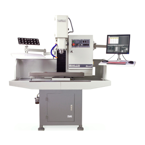
Tormach PCNC mills are intended for use as general purpose CNC mills. Pictured below is a typical
PCNC 1100 mill set up, including several opons.
Item # Component Item # Component
1 Electrical Cabinet 6PathPilot®Interface
2Serial Number Plate
Main Disconnect Switch
7Keyboard Table
8Machine Arm (2)
3 Red E-stop 9 Path Pilot Controller Compartment
4 Green Start Button 10 Storage Compartment
5 Operator Panel 11 Coolant Compartment
Figure 1.1
5
7
8
9
11
2
3
4
8
10
16
Other manuals for PCNC 1100
1
Table of contents
Other Tormach Power Tools manuals
