Tormach 770M User manual

TECHNICAL DOCUMENT
Owner's Guide:
770M® Power
Drawbar
TD10541: Owner's Guide: 770M® Power Drawbar (0618A) Page 1 Specifications subject to change without notice.
©Tormach® 2018
1.1 PURPOSE
This document gives instructions on installing a 770M® Power
Drawbar.
1.2 PRODUCT INFORMATION
Product: Power Drawbar
Quantity Description PN
1 1/4-inch Plastic Tube —
1 1/4-inch Push-to-Connect Air Fitting
Adapter
—
1 10 mm Shoulder Screw —
1 Anti-Seize 31273
1 Extend (Red) Air Line —
1 FRLFilter-Regulator-Lubricator 38829
1 Power Drawbar Button Assembly 38216
1 Power Drawbar Cylinder Assembly 37750
1 Quick-Release Pin —
1 Retract (White)Air Line —
8 Spring Washer —
4 Zip Tie 38436
NOTE: If any of these items are missing, we can help.
Email support@tormach.com to contact Tormach
Technical Support for guidance on how to proceed.
©Tormach® 2018
Specifications subject to change without notice.
Page 2 tormach.com
TD10541: Owner's Guide: 770M® Power Drawbar (0618A)
TECHNICAL DOCUMENT
2.1 SETTING UP THE POWER DRAWBAR
2.1.1 Required Tools
This procedure requires the following tools. Make sure that you
have them available before you begin.
lAdjustable wrench, two
lClean cloth
lMetric hex wrench set
lPaint pen
2.1.2 Air Requirements
The Power Drawbar uses compressed air to release tools held in
the spindle. You must make sure the site conforms to the
following air supply requirements.
lAir Pressure. Between 90 pounds per square inch (psi) and
120 psi (620 kPa - 825 kPa).
If the air supply is more than 120 psi (825 kPa), you must
use a regulator.
lDry Air. We recommend using a compressed air dryer,
desiccator, or filter between the air compressor and the
machine.
lLubricated Air. You must lubricate the air with air tool oil.
Use the FRLFilter-Regulator-Lubricator (PN 38829) or
similar for this purpose.
2.1.3 To Install the Power Drawbar
Installing the Power Drawbar varies if you have an (optional)
Automatic Tool Changer (ATC).
Power Drawbar Only
Installing the Power Drawbar involves the following steps.
Complete them in the order listed:
lStep 1: "Prepare the Machine" (below)
lStep 2: "Disassemble the Original Drawbar" (below)
lStep 3: "Assemble the Power Drawbar" (on the next page)
lStep 4: "Install the FRLFilter-Regulator-Lubricator" (page7)
lStep 5: "Set Up the FRLFilter-Regulator-Lubricator" (page7)
lStep 6: "Make Air Connections" (page8)
Power Drawbar and ATC
Installing the Power Drawbar and the ATC involves the following
steps. Complete them in the order listed:
lStep 1: "Prepare the Machine" (below)
lStep 2: "Disassemble the Original Drawbar" (below)
lStep 3: "Assemble the Power Drawbar" (on the next page)
lStep 4: "Install the FRLFilter-Regulator-Lubricator" (page7)
lStep 5: "Set Up the FRLFilter-Regulator-Lubricator" (page7)
lStep 6:Install the Automatic Tool Changer (ATC)
Prepare the Machine
1. If there is already a Tormach Tooling System® (TTS®) tool
holder in the spindle, remove it.
2. Make sure that you can access the inside of the spindle
cabinet: Jog the Z-axis down (-Z) until it is about six inches
from the machine table.
3. Power off the machine and the PathPilot® controller.
a. Push in the Emergency Stop button on the operator box,
which disables movement of the axes and the spindle.
b. From the PathPilot® interface, click Exit.
c. Turn the Main Disconnect switch to Off on the side of the
electrical cabinet.
Disassemble the Original Drawbar
CAUTION! Loose Objects Hazard: The original drawbar
contains spring-loaded hardware, which could quickly
become loose, causing serious injury. Before
disassembling the original drawbar, you must put on
safety eyewear that meets ANSI Z87+.
1. Put on eye protection.
2. Open the spindle door.
3. Use one hand to support the Tormach Tooling System®
(TTS®) collet, and use the other to turn and remove the
drawbar.
4. Set the collet and the drawbar aside.
©Tormach® 2018
Specifications subject to change without notice.
Page 3 tormach.com
TD10541: Owner's Guide: 770M® Power Drawbar (0618A)
TECHNICAL DOCUMENT
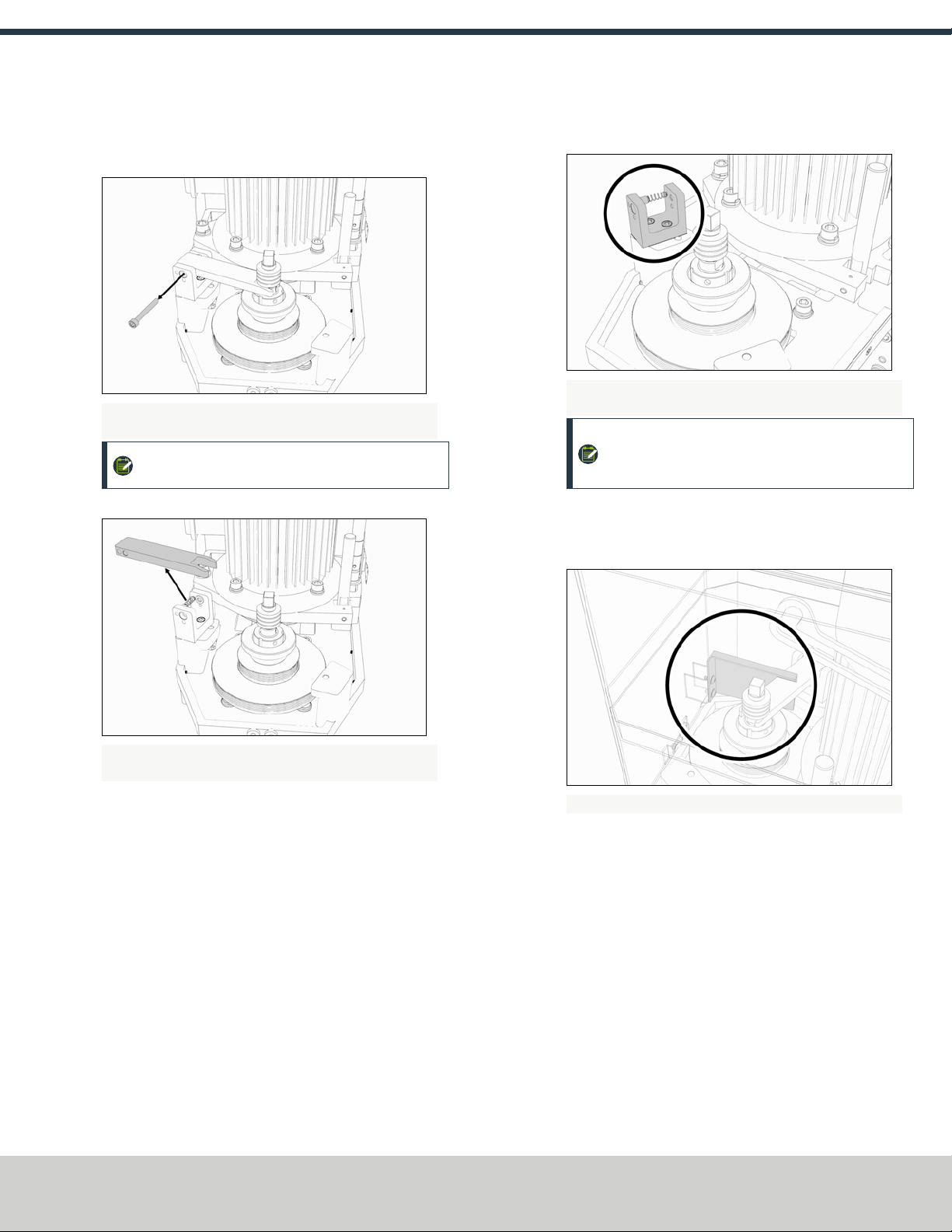
5. Use one hand to hold on to the spindle lock arm, and then
use a 5 mm hex wrench to remove the spindle lock arm
pivot screw.
Figure 2-1: Spindle lock arm pivot screw removed from the
original drawbar assembly.
NOTE: The spindle lock arm assembly contains
spring-loaded hardware.
6. Carefully remove the spindle lock arm.
Figure 2-2: Spindle lock arm removed from the original
drawbar assembly.
7. Use a 5 mm hex wrench to remove the spindle lock base and
components.
Figure 2-3: Spindle lock base from the original drawbar
assembly.
NOTE: Keep all components for future use. The
drawbar, drawbar bushing, and spindle lock are all
required to operate without a Power Drawbar.
8. Use a clean cloth to wipe down all exposed drawbar
mounting surfaces inside the spindle motor cabinet.
9. Remove the spindle lock arm on the spindle door.
Figure 2-4: Spindle lock arm on the spindle door.
Assemble the Power Drawbar
1. Identify the drawbar that you set aside in "Disassemble the
Original Drawbar" (on the previous page).
2. Remove the drawbar bushing from the drawbar, and set it
aside.
3. Put Anti-Seize (provided) on the bottom of the drawbar
head.
4. Identify the eight spring washers provided.
©Tormach® 2018
Specifications subject to change without notice.
Page 4 tormach.com
TD10541: Owner's Guide: 770M® Power Drawbar (0618A)
TECHNICAL DOCUMENT

5. Move one spring washer on the drawbar, with the convex
side of the spring washer toward the drawbar head.
Figure 2-5: Example of moving the convex side of a spring
washer toward the drawbar head.
6. Move another spring washer on the drawbar, with the
concave side of the spring washer toward the concave side
of the spring washer from Step 5.
Figure 2-6: Example of moving the concave sides of two
spring washers together.
7. Put Anti-Seize on the edge of the contact surface between
the pair of spring washers that you put on the drawbar in
Step 5 and Step 6.
8. Repeat steps 5-7 for the remaining six spring washers. Make
sure that you put Anti-Seize on the spring washers at every
contact point.
9. Examine the stack of spring washers. Make sure that all
eight spring washers are installed on the drawbar and
arranged in four sets of opposing pairs.
Figure 2-7: Example of all eight spring washers installed on
the drawbar.
10. Identify the drawbar bushing that you set aside in Step 2,
and reinstall it on the drawbar. Make sure that the smaller
diameter of the drawbar bushing is toward the bottom of
the drawbar.
11. Put Anti-Seize on the top of the drawbar bushing.
12. Put Anti-Seize on the bottom threads of the drawbar.
Figure 2-8: Example of the locations to apply Anti-Seize on a
drawbar assembly.
13. Put Anti-Seize on the outside taper of the Tormach Tooling
System® (TTS®) collet. Make sure that there is no Anti-Seize
on the inside of the collet.
14. Insert the drawbar assembly into the spindle.
©Tormach® 2018
Specifications subject to change without notice.
Page 5 tormach.com
TD10541: Owner's Guide: 770M® Power Drawbar (0618A)
TECHNICAL DOCUMENT
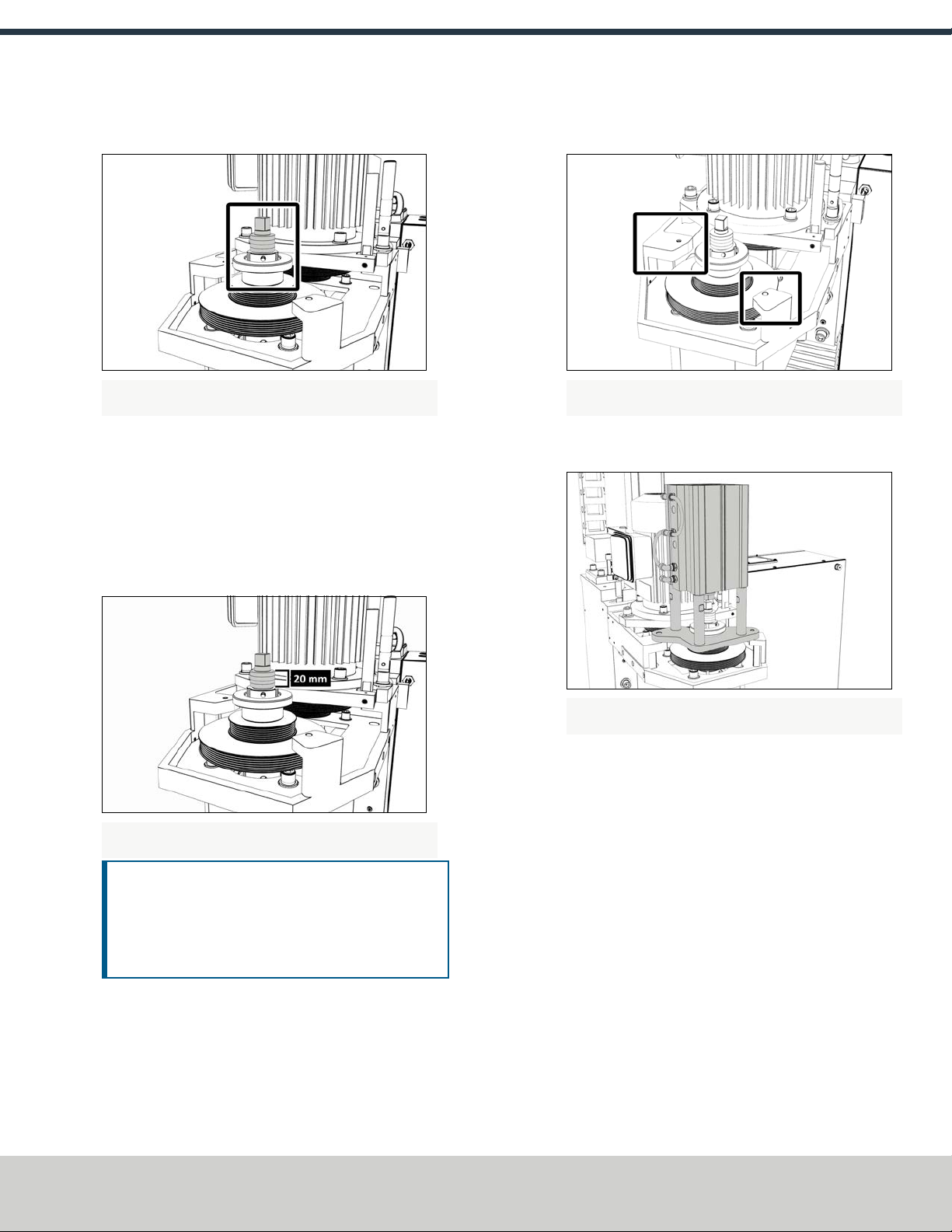
15. Use one hand to insert the collet into the spindle, and then
turn in the drawbar.
Figure 2-9: Drawbar assembly installed in the spindle motor
cabinet.
16. Hand tighten the drawbar.
17. Use one hand to insert an empty Tormach Tooling System®
(TTS®) tool holder into the collet, and then use an adjustable
wrench to tighten the collet into the drawbar.
18. Use two large, adjustable wrenches to tighten the Power
Drawbar until the spring washer stack is compressed to a
height of 20 mm.
Figure 2-10: Example of a correctly compressed spring
washer stack.
NOTICE! After the initial installation, you must
complete a final drawbar tension adjustment. For
more information, go to "Adjust the Drawbar Tension"
(page9). If you don't complete a drawbar tension
adjustment, there's a risk of tool pull-out.
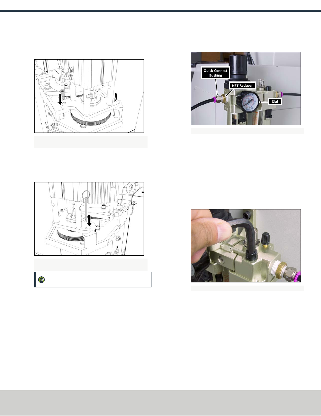
19. Identify the Power Drawbar cylinder assembly provided.
20. Identify the Power Drawbar mounting surfaces inside of the
spindle motor cabinet as shown in the following image.
Figure 2-11: Power Drawbar mounting surfaces inside of the
spindle motor cabinet.
21. Put the Power Drawbar cylinder assembly on the mounting
surface.
Figure 2-12: Power Drawbar cylinder assembly inside of the
spindle motor cabinet.
22. Identify the 10 mm shoulder screw provided, and then put
anti-seize on its threads.
©Tormach® 2018
Specifications subject to change without notice.
Page 6 tormach.com
TD10541: Owner's Guide: 770M® Power Drawbar (0618A)
TECHNICAL DOCUMENT
23. Use a 5 mm hex wrench to install the 10 mm shoulder
screw on the Power Drawbar cylinder’s mount plate.
The unit is securely installed to the spindle head.
Figure 2-13: 10 mm shoulder screw installed on the Power
Drawbar cylinder's mount plate.
24. Identify the quick- release pin provided, and then insert it on
the Power Drawbar cylinder’s mount plate.
The quick-release pin allows the Power Drawbar cylinder to
pivot within the spindle motor cabinet.
Figure 2-14: Quick-release pin installed on the Power
Drawbar cylinder's mount plate.
NOTE: The Power Drawbar cylinder intentionally
floats.
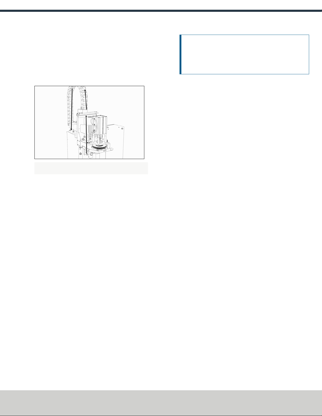
Install the FRLFilter-Regulator-Lubricator
1. Clean the FRL to make sure that it's free of dust.
2. Remove and discard the plastic inserts from the FRL.
3. Put two layers of thread seal tape on the threads of the dial.
4. Install the dial on the front of the FRL.
5. Install two quick-connect bushings into the two
NPTreducers.
6. Put two layers of thread seal tape on the threads of the NPT
reducers.
7. Install one NPT reducer into the valve housing on either side
of the FRL.
Figure 2-15: FRL installed on a mill's backsplash.
8. Determine the location to install the FRL.
9. Use the FRL bracket as a template to mark and drill two
holes.
10. Install the FRL bracket using your own hardware.
11. Connect the air lines to the quick-connect bushings that you
installed in Step 5.
Set Up the FRLFilter-Regulator-Lubricator
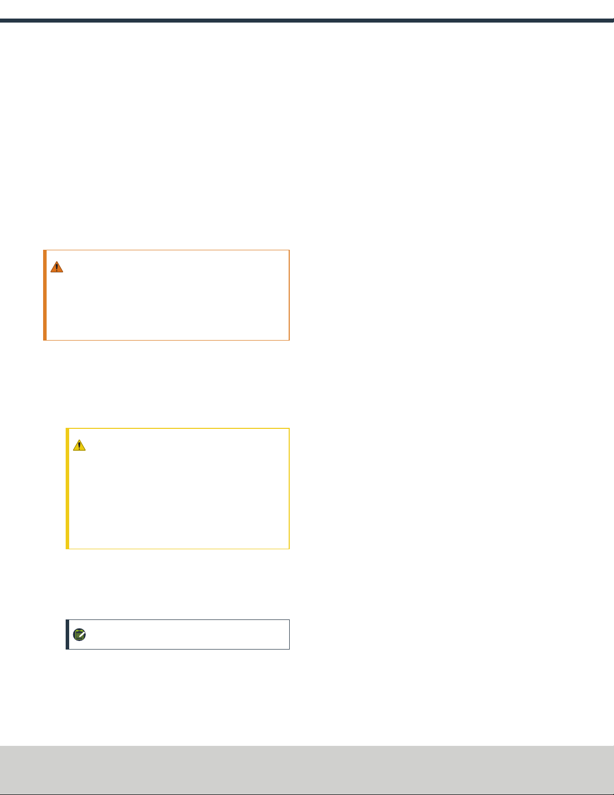
1. Use a hex wrench to open the fill port on the FRL.
Figure 2-16: Example of opening the fill port on an FRL.
2. Use a small funnel to fill the lubricator bowl with standard
air tool oil. Make sure that you only use oil that is
specifically designed for air tools.
3. Turn the adjustment knob halfway toward the +.
4. Flush all air bubbles from the system.
©Tormach® 2018
Specifications subject to change without notice.
Page 7 tormach.com
TD10541: Owner's Guide: 770M® Power Drawbar (0618A)
TECHNICAL DOCUMENT

5. Examine the sight window for air bubbles. When there are
no air bubbles in the sight window, and a drop of lubricant is
on the bottom of the stem, turn the adjustment knob one-
quarter back.
Figure 2-17: Components to flush the air from the FRL.
Make Air Connections
NOTE: If you have an (optional) Automatic Tool Changer
(ATC), install it now.
1. Identify the button box assembly provided.
2. Use a 3 mm hex wrench to remove the four M5 × 0.8 - 10
button head screws securing the cover to the button box,
and then remove the cover.
3. Use two M4 × 0.7 - 50 socket head cap screws to install the
button box base, standoffs, and button assembly to the mill
head.
Figure 2-18: Button box base installed on the mill head.
4. Remove and discard the shipping plugs on the Power
Drawbar.
5. Identify the Retract (white) air line provided, and then
connect one end to the Retract port on the Power Drawbar
button.
Figure 2-19: Example of the Power Drawbar air line routing.
6. Route the loose end of the Retract air line to the Power
Drawbar cylinder, and then connect it to the bottom-most
elbow fitting.
Figure 2-20: Retract fitting on the Power Drawbar cylinder.
7. Identify the Extend (red) air line provided, and then connect
one end to the Extend port on the Power Drawbar button.
8. Route the loose end of the Extend air line to the Power
Drawbar cylinder, and then connect it to the upper-most tee
fitting.
Figure 2-21: Extend fitting on the Power Drawbar cylinder.
©Tormach® 2018
Specifications subject to change without notice.
Page 8 tormach.com
TD10541: Owner's Guide: 770M® Power Drawbar (0618A)
TECHNICAL DOCUMENT
9. Use three cable ties to secure both air lines together.
10. Identify the 1/4-inch plastic tube provided, and then connect
one end to the Air Supply push-to-connect elbow on the
Power Drawbar button.
11. Route the loose end of the 1/4-inch plastic tube through the
energy chain and toward the FRL.
Figure 2-22: Example of the air line routing through the
energy chain.
12. Connect the 1/4-inch plastic tube to the Output port on the
FRL.
13. Identify the 1/4-inch plastic tube provided, and then connect
one end to the Input port on the FRL.
14. Identify the 1/4-inch push-connect air fitting adapter
provided, and then put it on the loose end of the 1/4-inch
plastic tube.
15. Route the 1/4-inch plastic tube to your shop's air supply and
connect it with the adapter.
16. Use a 3 mm hex wrench to reinstall the button box cover
with the screws that you set aside in Step 2.
2.1.4 To Adjust the Power Drawbar
After installing the Power Drawbar, you must adjust it. Complete
the following steps in the order listed:
lStep 1: "Adjust the Drawbar Tension" (below)
lStep 2: "Adjust the Initial Setup" (below)
Adjust the Drawbar Tension
The purpose of this adjustment is to set the highest possible
drawbar tension while still allowing the Power Drawbar cylinder to
release the tool. For more information, go to "About Drawbar
Tension" (below).
NOTICE! After the initial installation, you must examine the
drawbar tension weekly. During periods of heavy use,
examine the drawbar tension more frequently. If you don't,
there's a risk of tool pull-out.
To adjust the drawbar tension:
1. Install an empty Tormach Tooling System® (TTS®) tool
holder in the collet.
2. Use one hand to support the tool holder, and then push the
Release Tool button. Do one of the following:
lIf the tool holder releases: Use two adjustable wrenches
to tighten the Power Drawbar in quarter-turn increments
while pushing the Release Tool button after each turn.
Stop when the tool holder does not release.
lIf the tool holder does not release: Use two adjustable
wrenches to loosen the Power Drawbar in quarter-turn
increments while pushing the Release Tool button. Stop
when the tool holder releases.
3. Make a visual reference to help you set or adjust the
drawbar tension in the future: Use a paint pen to make a
witness mark on both the head of the drawbar and the end
of the spindle.
About Drawbar Tension
While machining, the Tormach Tooling System® (TTS®) collet
holds a Tormach Tooling System® (TTS®) tool holder in the spindle
by applying a clamping force to both the shank and the shoulder of
the tool. The tension force that is applied to the drawbar pulls the
Tormach Tooling System® (TTS®) collet into the spindle taper,
which then applies the clamping force to the Tormach Tooling
System® (TTS®) tool.
The force on the drawbar, known as the drawbar tension, is
applied differently depending on the tool changing method:
lWhen you change tools manually, the tension is applied
when you tighten the drawbar into the collet using a
wrench.
lWhen you change tools with the Power Drawbar, the tension
is applied by the compressed spring washers.
Adjust the Initial Setup
The purpose of this adjustment is to make sure that there is
enough clearance between the end of the drawbar and the Power
Drawbar cylinder.
©Tormach® 2018
Specifications subject to change without notice.
Page 9 tormach.com
TD10541: Owner's Guide: 770M® Power Drawbar (0618A)
TECHNICAL DOCUMENT

NOTICE! If you don't do this adjustment, there's a risk that
the drawbar can loosen, or that operations can be louder than
normal.
1. Examine the space between the hex head screw on the
Power Drawbar cylinder's rod and the top of the drawbar.
Figure 2-23: Example of a correctly spaced drawbar and
Power Drawbar cylinder.
2. Make sure that the gap is between 1 mm and 3 mm.
Depending on the size of the gap, do one of the following:
lIf the gap is between 1 mm and 3 mm, you have
completed adjusting the initial setup.
lIf the gap is less than 1 mm or greater than 3 mm, go to
Step 3.
3. Disconnect the shop's air supply from the Power Drawbar
button.
4. Pull out the quick-release pin.
5. Pivot the Power Drawbar cylinder assembly to the left so
that you can access the Power Drawbar cylinder's rod.
Figure 2-24: Power Drawbar cylinder pivoted to the left.
6. Use an adjustable wrench to remove the hex head screw on
the Power Drawbar cylinder’s rod.
Figure 2-25: Hex head screw on the Power Drawbar
cylinder's rod.
7. Remove the M16 washer from the Power Drawbar cylinder’s
rod, and set it aside.
Figure 2-26: M16 washer removed from the Power Drawbar
cylinder's rod.
8. Use an adjustable wrench to reinstall the hex head screw,
and then tighten it completely.
9. Pivot the Power Drawbar cylinder to the original location.
10. Push in the quick-release pin.
11. Reconnect the shop's air supply to the Power Drawbar
button.
12. Examine the space between the hex head screw on the
Power Drawbar cylinder’s rod and the top of the drawbar.
13. Makesure that the gap is between 1 mm and 3 mm.
Depending on the size of the gap, do one of the following:
lIf the gap is between 1 mm and 3 mm, go to "Operating
the Power Drawbar" (page12).
lIf the gap is less than 1 mm, go to Step 14.
14. Identify the three extra M16 flat washers provided.
©Tormach® 2018
Specifications subject to change without notice.
Page 10 tormach.com
TD10541: Owner's Guide: 770M® Power Drawbar (0618A)
TECHNICAL DOCUMENT

15. Put one M16 flat washer under each mounting post on the
Power Drawbar cylinder.
©Tormach® 2018
Specifications subject to change without notice.
Page 11 tormach.com
TD10541: Owner's Guide: 770M® Power Drawbar (0618A)
TECHNICAL DOCUMENT
3.1 OPERATING THE POWER DRAWBAR
The Power Drawbar is designed to provide more than sufficient
tool holding force to resist regular cutting loads. Machining
practices outside of these situations may result in tool holder pull-
out.
While operating the machine, avoid the following conditions:
lHigh chatter machining
lHigh cutter engagement (chip load) combined with high
helix angle cutter geometries
3.1.1 Change Tools with the Power Drawbar
WARNING! Ejection Hazard: Wait until the spindle is
completely stopped before pressing the Release Tool
button. Never press the Release Tool button while the
spindle is turning. Tooling can become a dangerous
projectile if it's released from a turning spindle.
1. With one hand on the Tormach Tooling System® (TTS®) tool
holder installed in the spindle, press and hold the Release
Tool button.
The Power Drawbar activates and releases the tool holder in
the spindle. Remove the tool from the spindle.
CAUTION! Pinch Hazard: Keep fingers clear of the
Tormach Tooling System® (TTS®) collet when
changing tools. Never put your fingers into an
unclamped Tormach Tooling System® (TTS®) collet.
If your fingers are in the Tormach Tooling System®
(TTS®) collet as it closes, it can crush or pinch your
fingers.
2. Insert a new tool holder.
3. Let go of the Release Tool button.
The Power Drawbar reverts to clamp mode and secures the
tool in the spindle.
NOTE: In the event of an air pressure loss, the
power drawbar reverts to clamp mode.
While the Power Drawbar is in clamp mode, make sure that
there's always a tool in the collet. Retracting the Power
Drawbar to clamp mode with no tool in the collet will
eventually fatigue the collet, and could shorten its service
life.
©Tormach® 2018
Specifications subject to change without notice.
Page 12 tormach.com
TD10541: Owner's Guide: 770M® Power Drawbar (0618A)
TECHNICAL DOCUMENT

4.1 MAINTAINING THE POWER DRAWBAR
Read the following sections to understand how to maintain the
Power Drawbar:
l"Examine Air Pressure" (below)
l"Lubricate the Power Drawbar" (below)
l"Examine Wear Items" (below)
4.1.1 Examine Air Pressure
Appropriate air supply helps with smooth actuation, and prevents
premature component failure. Examine the air to the Power
Drawbar for the following:
lMake sure that it's between 90 psi and 120 psi.
lMake sure that it's been lubricated with common air tool oil.
4.1.2 Lubricate the Power Drawbar
Every 5000 cycles (or six months — whichever comes first),
use Anti-Seize to lubricate the following parts on the Power
Drawbar:
oContact surfaces between spring washers
oEccentric pivot mount
oTop of the drawbar (below the drawbar flange and the
spring washers)
4.1.3 Examine Wear Items
Examine the following wear items regularly:
oSpring Washers. Inspect all spring washers once a month
for cracks. If they're damaged, replace them immediately
with the following item:
oPower Drawbar Spring Washer (PN 31319)
oTormach Tooling System® (TTS®) Collet and Drawbar.
Using the Power Drawbar may cause these items to wear
faster than with a manual drawbar. Inspect them
regularly, and immediately replace any damaged items
with the following:
oR8 Drawbar (PN 38793)
oPower Drawbar Alignment Bushing (PN 31330)
oTormach Tooling System® (TTS®) Adapter Collet: R8
(PN 35356)
oPower Drawbar Cylinder Rebuild Kit (PN 32093)
©Tormach® 2018
Specifications subject to change without notice.
Page 13 tormach.com
TD10541: Owner's Guide: 770M® Power Drawbar (0618A)
TECHNICAL DOCUMENT
Other manuals for 770M
2
Table of contents
Other Tormach Power Tools manuals


