Toro 38701 User manual

FormNo.3439-892RevB
PowerBroom
ModelNo.38701—SerialNo.400000000andUp
Registeratwww.Toro.com.
OriginalInstructions(EN)*3439-892*

ItisaviolationofCaliforniaPublicResourceCode
Section4442or4443touseoroperatetheengineon
anyforest-covered,brush-covered,orgrass-covered
landunlesstheengineisequippedwithaspark
arrester,asdenedinSection4442,maintainedin
effectiveworkingorderortheengineisconstructed,
equipped,andmaintainedforthepreventionofre.
Theenclosedengineowner'smanualissupplied
forinformationregardingtheUSEnvironmental
ProtectionAgency(EPA)andtheCaliforniaEmission
ControlRegulationofemissionsystems,maintenance,
andwarranty.Replacementsmaybeorderedthrough
theenginemanufacturer.
WARNING
CALIFORNIA
Proposition65Warning
Theengineexhaustfromthisproduct
containschemicalsknowntotheStateof
Californiatocausecancer,birthdefects,
orotherreproductiveharm.
Introduction
Thismachineisintendedtobeusedbyresidential
homeownersorprofessional,hiredoperators.Itis
designedforremovingsnow,dust,anddirtfrompaved
surfaces,suchasdrivewaysandsidewalks,and
othersurfacesfortrafconresidentialorcommercial
properties,aswellasthatchfromgrass.
Readthisinformationcarefullytolearnhowtooperate
andmaintainyourproductproperlyandtoavoid
injuryandproductdamage.Youareresponsiblefor
operatingtheproductproperlyandsafely.
Visitwww.Toro.comforproductsafetyandoperation
trainingmaterials,accessoryinformation,helpnding
adealer,ortoregisteryourproduct.
Wheneveryouneedservice,genuineToroparts,or
additionalinformation,contactanAuthorizedService
DealerorT oroCustomerServiceandhavethemodel
andserialnumbersofyourproductready.Figure1
identiesthelocationofthemodelandserialnumbers
ontheproduct.Writethenumbersinthespace
provided.
Important:Withyourmobiledevice,youcan
scantheQRcodeontheserialnumberdecal(if
equipped)toaccesswarranty,parts,andother
productinformation.
g325100
Figure1
1.Modelandserial-numberlocation
ModelNo.
SerialNo.
Thismanualidentiespotentialhazardsandhas
safetymessagesidentiedbythesafety-alertsymbol
(Figure2),whichsignalsahazardthatmaycause
seriousinjuryordeathifyoudonotfollowthe
recommendedprecautions.
g000502
Figure2
1.Safety-alertsymbol
Thismanualuses2wordstohighlightinformation.
Importantcallsattentiontospecialmechanical
informationandNoteemphasizesgeneralinformation
worthyofspecialattention.
©2020—TheToro®Company
8111LyndaleAvenueSouth
Bloomington,MN554202
Contactusatwww.Toro.com.
PrintedintheUSA
AllRightsReserved

Contents
Safety.......................................................................3
GeneralSafety...................................................3
SlopeIndicator...................................................4
SafetyandInstructionalDecals..........................5
ProductOverview.....................................................7
Controls.............................................................7
Specications....................................................8
Attachments/Accessories...................................8
BeforeOperation...................................................9
BeforeOperationSafety.....................................9
FillingtheFuelTank............................................9
CheckingtheSweepingPath..............................9
AdjustingtheBroomHeight..............................10
DuringOperation.................................................10
DuringOperationSafety...................................10
OperatingtheEngine.........................................11
DrivingtheMachine..........................................13
OperatingtheBroom........................................14
AdjustingtheBroomSideAngle........................15
UsingtheAlternateCasterLocation..................16
ClearingaCloggedBroom................................16
AfterOperation....................................................16
AfterOperationSafety......................................16
PreventingFreeze-upafterUse........................17
TransportingtheMachine.................................17
Maintenance...........................................................18
RecommendedMaintenanceSchedule(s)...........18
MaintenanceSafety..........................................18
PreparingforMaintenance...............................18
Lubrication........................................................19
EngineMaintenance.........................................19
FuelSystemMaintenance................................22
DriveSystemMaintenance...............................23
BroomMaintenance.........................................24
BeltMaintenance..............................................26
ChassisMaintenance.......................................30
Storage...................................................................30
StorageSafety..................................................30
PreparingtheMachineforStorage...................30
RemovingtheMachinefromStorage................31
Troubleshooting......................................................32
Safety
Thismachinehasbeendesignedinaccordancewith
ANSI/OPEIB71.3andANSIB71.4specications.
Thisproductiscapableofinjuringhandsandfeetand
ofthrowingobjects.Failuretoobservethefollowing
safetyinstructionscouldresultinseriousinjury.
Alwaysfollowallsafetyinstructionstoavoidserious
personalinjury.
GeneralSafety
•Readandunderstandthecontentsofthis
Operator’sManualbeforeyoustarttheengine.
•Ensurethateveryoneusingthisproductknows
howtouseit,knowshowtoshutofftheengine
quickly,andunderstandsthewarnings.
•Releasethebroom-drivelever,traction-drivelever,
shutofftheengine,andwaitforallmovingparts
tostopwheneveryouleavetheoperatingposition
foranyreason.
•Donotputyourhandsorfeetnearorunder
movingpartsonthemachine.Keepclearofthe
dischargeopeningatalltimes.
•Donotoperatethemachinewithoutallguards
andothersafetyprotectivedevicesinplaceand
working.
•Keepbystanders,especiallysmallchildren,outof
theoperatingarea.
•Neverallowchildrentooperatethemachine.
3
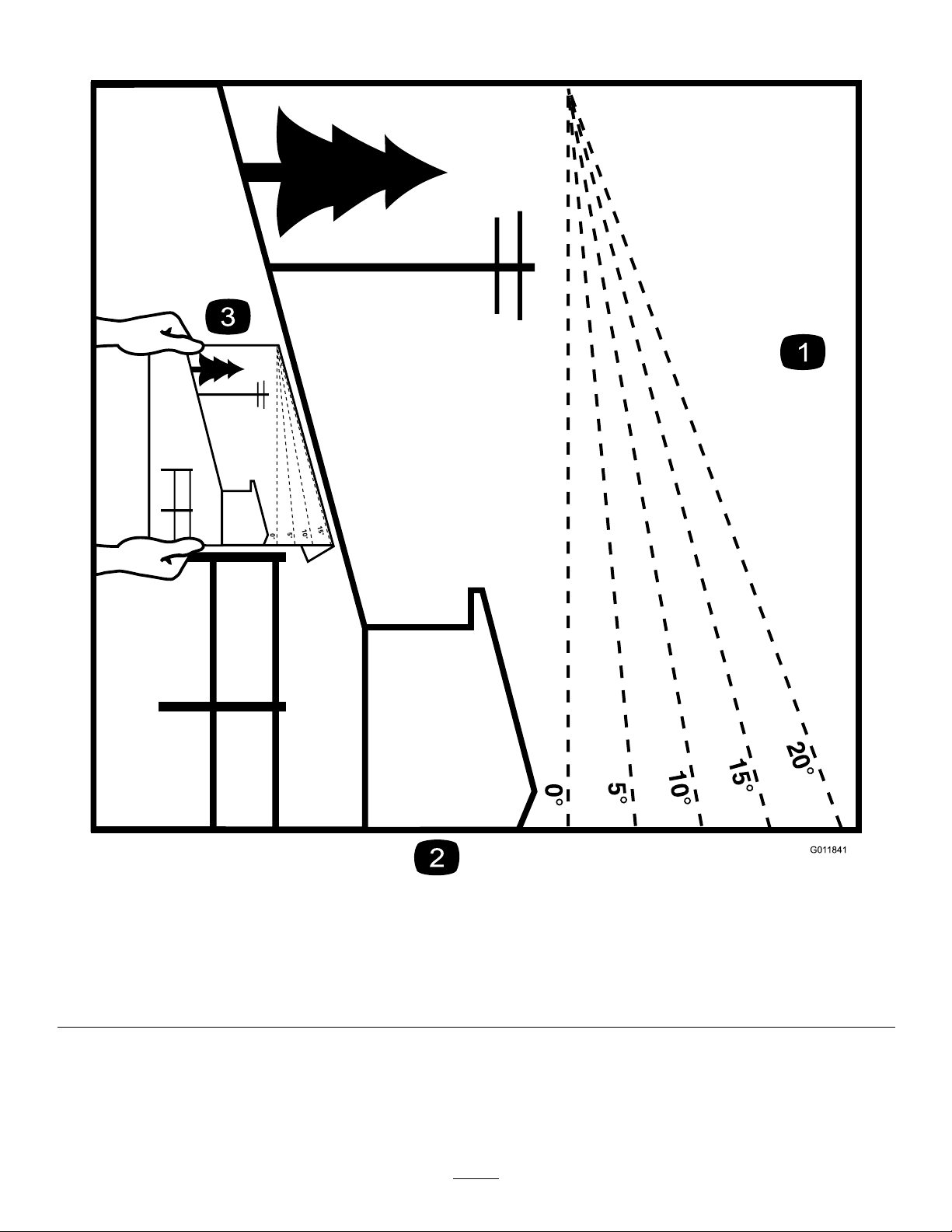
SlopeIndicator
g011841
Figure3
1.Themaximumslopeyoucansafelyoperatethemachineonis10°.Usetheslopeindicatortodeterminethedegreeofslopeof
hillsbeforeoperating.Donotoperatethismachineonaslopegreaterthan10°.Foldalongtheappropriatelinetomatchthe
recommendedslope.
2.Alignthisedgewithaverticalsurface,atree,building,fencepole,etc.
3.Exampleofhowtocompareslopewithfoldededge.
4
SafetyandInstructionalDecals
Safetydecalsandinstructionsareeasilyvisibletotheoperatorandarelocatednearanyarea
ofpotentialdanger.Replaceanydecalthatisdamagedormissing.
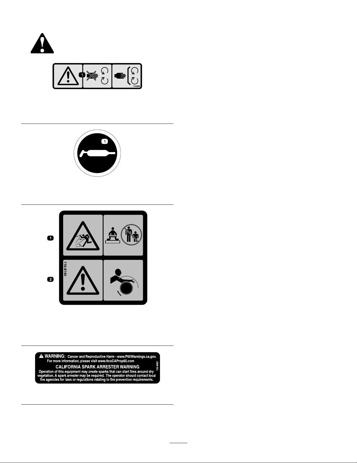
decal112-9028
112-9028
1.Warning—stayawayfrommovingparts;keepallguardsin
place.
decal115-2903
115-2903
1.Grease
decal116-8140
116-8140
1.Thrownobjecthazard—Do
notoperatewhenpeople
andpetsareinthearea.
2.Warning—Entanglement
hazard—stayclearofthe
rotatingbroom.
decal133-8062
133-8062
5
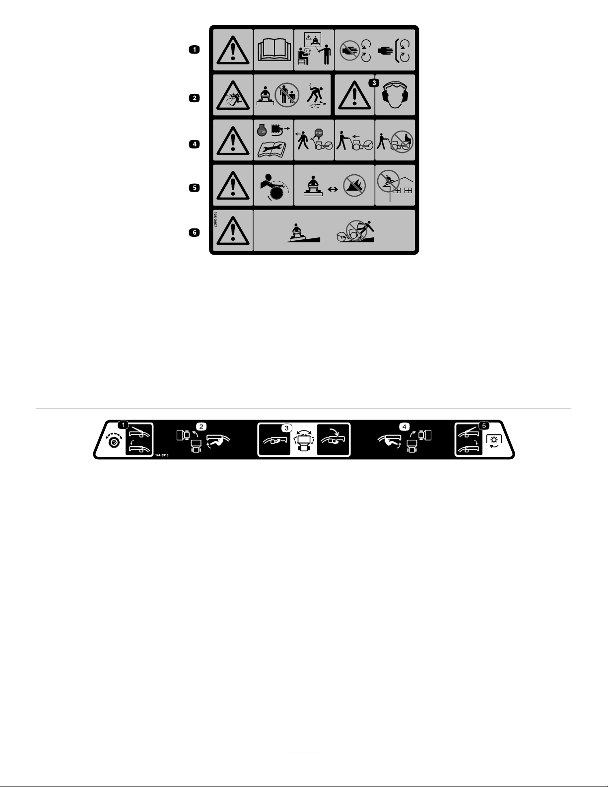
decal135-2867
135-2867
1.Warning-ReadtheOperator’sManual.DoNotoperatethis
machineunlessyouaretrained.Stayawayfrommoving
parts;keepallguardsinplace.
4.Warning-Stopengineandremovesparkplugbeforeadjusting,
servicing,orcleaningmachineandattachments.Before
leavingtheoperator’sposition,disengagebroom,traction
drive,andstopengine.Lookbehindandtothesidebefore
changingdirections.DoNotcarrypassengers.
2.Thrownobjecthazard-DoNotoperatewhenpeopleandpets
areinthearea;pickupobjectsthatcouldbethrownbybroom.
5.Warning-Entanglementhazard-stayclearofrotatingbroom.
Broombristleswillmeltorburn-keepawayfromextreme
heatorame.DoNotoperateonanyrooforotherelevated
surface.
3.Warning-Wearhearingprotection.6.Warning-Operateacrossslopesnotupanddown.Use
extremecautionwhenoperatingonslopes.
decal144-0316
144-0316
1.Engagethetraction-controllevertoactivatethetractiondrive.4.Engagetheright-turnlevertoturnright.
2.Engagetheleft-turnlevertoturnleft.5.EngagethePTOlevertoactivatethePTO.
3.Engagethebroom-anglelevertoadjustthebroom.
6

ProductOverview
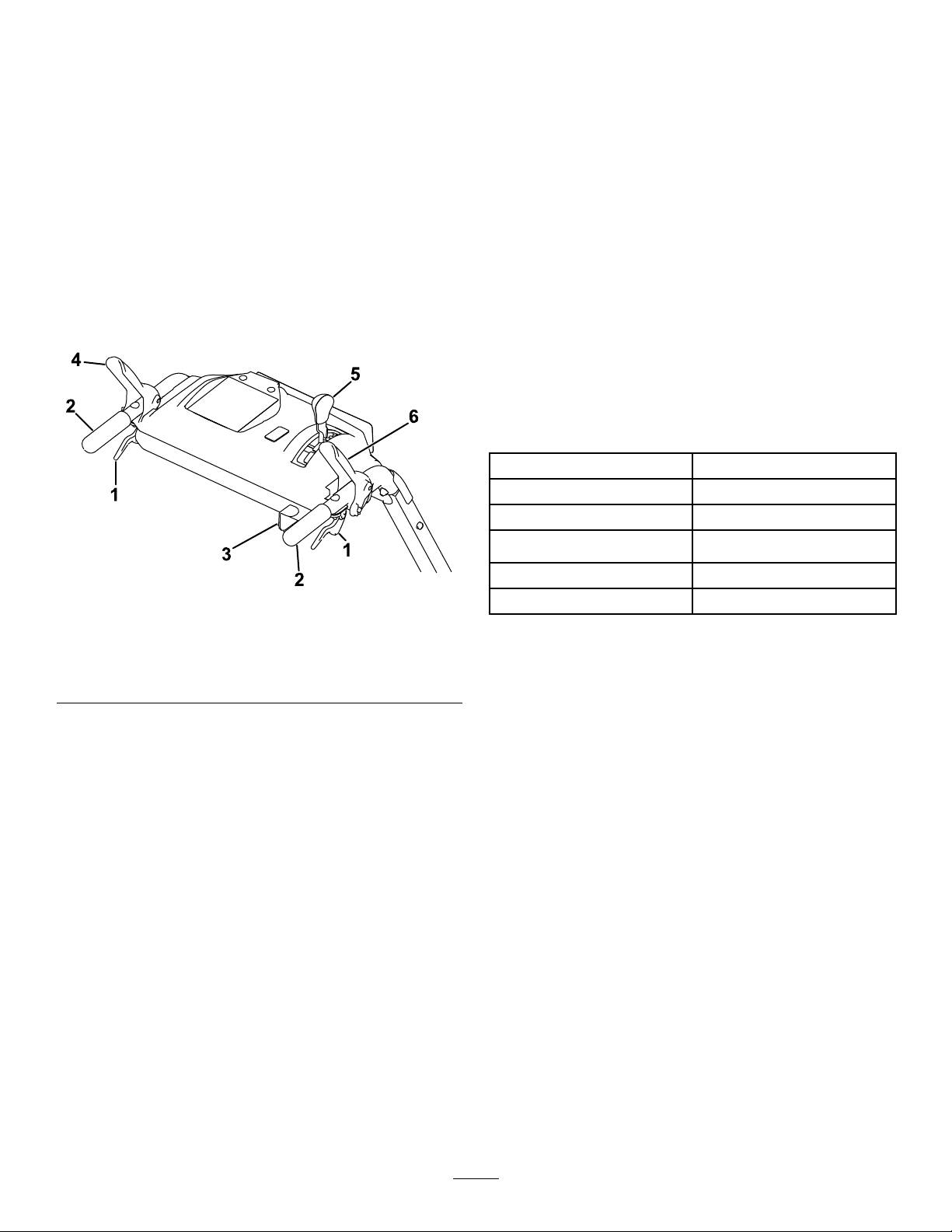
g325102
Figure4
1.Wheel-clutchlever6.Traction-drivelever
2.Broom-anglelever7.Fuel-tankcap
3.Broom-drivelever8.Broomandhood
4.Speed-selectorlever9.Broom-height-adjustment
pin
5.Handbargrip
Controls
Determinetheleftandrightsidesofthemachinefrom
thenormaloperatingposition.
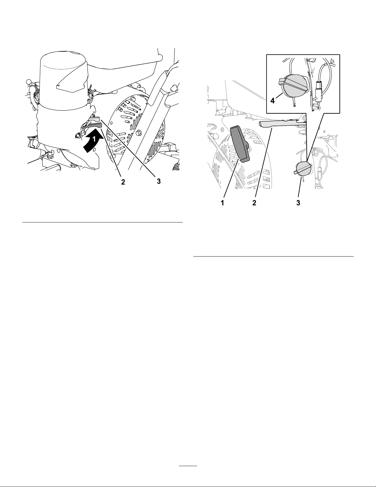
ChokeControl
Thechokecontrolisthetopleverlocatedontherear,
leftsideoftheengineabovethefuel-shutoffvalve
(Figure5).
Thechokeisusedtoaidinstartingacoldengine.
MovetheleverlefttotheONpositionforacoldstart.
DonotrunawarmenginewiththechokeintheON
position.
g326826
Figure5
1.Chokecontrol4.Recoil-starthandle
2.Fuel-shutoffvalve5.EngineOn/Offswitch
3.Throttlecontrol
Fuel-ShutoffValve
Usethefuel-shutoffvalvetoshutoffthefuelwhen
youwillnotusethemachineforafewdays,parkthe
machineinsideabuilding,ortransportthemachineto
andfromthejobsite(Figure5).
Movethelevertothelefttoshutoffthefuel.Movethe
levertotherighttoturnonthefuel.
ThrottleControl
Thethrottlecontrolislocatedontherear,rightsideof
theengineandbelowthefueltank(Figure5).
Thethrottleisusedtocontrolenginespeed.Moving
thethrottlecontroltotheleftincreasestheengine
speed,andmovingitrightdecreasestheengine
speed.
EngineOn/OffSwitch
Locatedontherightsideoftheengine(Figure5).
RotatetheswitchclockwisetotheONposition
beforestartingtheengine.Rotatetheswitch
counterclockwisetotheOFFpositiontoshotoffthe
engine.
7
Wheel-ClutchLevers
Thewheel-clutchleversarelocatedbelowtheright
andlefthandles.
Thewheelclutchleversallowthedrivetomomentarily
disengageto1orbothwheelswiththetraction-drive
leversqueezed.Thisallowsforeasierturningand
maneuveringthemachine(Figure6).
Note:Squeezingbothwheelclutchlevers
simultaneouslydisengagesthedrivetobothwheels
(free-wheeling).Thisenablesyoutomanuallymove
themachinebackwardwithoutstoppingtoshiftitinto
areversegear.Italsoallowsyoutomaneuverand
transportthemachinemoreeasilywhentheengine
isnotrunning.
g325105
Figure6
1.Wheel-clutchlever4.Traction-drivelever
2.Handle5.Speed-selectorlever
3.Broom-anglelever6.Broom-drivelever
Broom-DriveLever
Thebroom-driveleverislocatedabovetheright
handle(Figure6).
Toengagethebroom,squeezethelevertothehandle.
Todisengagethebroom,releasetherightlever.
Traction-DriveLever
Thetraction-driveleverislocatedabovetheleft
handle(Figure6).
Thetraction-drivelevercontrolstheforwardand
reversemotionofthemachine.T oengagethetraction
drive,squeezethelevertothehandle.
Note:Holdingdownthetraction-driveleveragainst
thehandleengagesthetractiondrivetobothwheels.
Speed-SelectorLever
Thespeed-selectionleverislocatedonthemain
consolepanel(Figure6).
Thespeedselectorhas6forwardand2reverse
settings.Tochangespeeds,releasethetraction-drive
lever,andshiftthespeed-selectorlevertothedesired
setting.Theleverlocksinanotchateachspeed
setting.
Broom-AngleLever
Thebroom-angleleverislocatedattherighthandle
(Figure6).
Thebroom-anglelevercontrolstheanglelock.The
broomanglecanbelockedinto3positions:straight
ahead,orangledtotheleftorright19°.
Specications
Width118cm(46.5inches)
Length185.5cm(73inches)
Height105.5cm(41.5inches)
Weight151kg(333lb)
Enginespeed(noload)Fullspeed:3600±100rpm
Fueltankcapacity4.1L(1.0USgallon)
Attachments/Accessories
AselectionofT oroapprovedattachmentsand
accessoriesisavailableforusewiththemachine
toenhanceandexpanditscapabilities.Contact
yourAuthorizedServiceDealerorauthorizedToro
distributororgotowww.T oro.comforalistofall
approvedattachmentsandaccessories.
Toensureoptimumperformanceandcontinuedsafety
certicationofthemachine,useonlygenuineT oro
replacementpartsandaccessories.Replacement
partsandaccessoriesmadebyothermanufacturers
couldbedangerous,andsuchusecouldvoidthe
productwarranty.
8

Operation
BeforeOperation
BeforeOperationSafety
GeneralSafety
•Wearappropriateclothing,includingeye
protection;longpants;substantial,slip-resistant
footwear;andhearingprotection;alsoweara
respiratorordustmaskindustyconditions.Tie
backlonghair,securelooseclothing,anddonot
wearloosejewelry.
•Thoroughlyinspecttheareawhereyouwillusethe
machine,andremovealldoormats,sleds,boards,
wires,andotherforeignobjects.
•Ifashield,safetydevice,ordecalisdamaged,
illegible,ormissing,repairorreplaceitbefore
beginningoperation.Also,tightenanyloose
fasteners.
FuelSafety
Fuelisextremelyammableandexplosive.Areor
explosionfromfuelcanburnyouandothers.
•Topreventastaticchargefromignitingthefuel,
placethecontainerand/ormachineontheground
beforelling,notinavehicleoronanobject.
•Fillthefueltankoutdoorswhentheengineiscold.
•Replacethefuelcapsecurelyandwipeupspills.
•Donothandlefuelwhensmokingoraroundan
openameorsparks.
•Storefuelinanapprovedfuelcontainer,outofthe
reachofchildren.
•Whenfuelisinthetank,tipthemachineonlyas
directedintheinstructions.
•Ifyouspillfuelonyourclothing,changeyour
clothingimmediately.
FillingtheFuelTank
TypeUnleadedgasoline
Minimumoctanerating87(US)or91(research
octane;outsidetheUS)
EthanolNomorethan10%byvolume
MethanolNone
MTBE(methyltertiarybutyl
ether)
Lessthan15%byvolume
OilDonotaddtothefuel
Useonlyclean,fresh(nomorethan30daysold),fuel
fromareputablesource.
FillthefueltankasshowninFigure7;donotllabove
thebottomofthefueltankneck.
g216203
Figure7
Important:Forbestresults,purchaseonlythe
quantityoffuelthatyouexpecttousein30days.
Otherwise,addfuelstabilizer/conditionertofresh
fuelasdirectedbythefuel-stabilizer/conditioner
manufacturer.
CheckingtheSweeping
Path
Abroomsweepswiththetipsofitsbristles.Whenyou
applytoomuchdownwardpressure,thebroomno
longerusesitstips;thebroomisnowworkingwiththe
sidesofthebristles.Thislimitstheickingactionof
thebristlesandsweepingeffectiveness,decreasing
theservicelifeofthebroom.
1.Drivethemachinetoaat,dustyareaandstop
themachine.
2.Withtheenginerunning,movethethrottle
midwaybetweentheSLOWandFASTpositions.
3.Squeezethebroom-drivecontrol,andallowthe
broomtorotatefor30seconds.
4.Releasethebroom-drivecontrol,shutoffthe
engine,andwaitforallmovingpartstostop.
5.Checktheareasweptbythebroom.The
broom-sweepareashouldequalthefullbroom
widthandamaximumdepthof51to102mm(2
to4inches).
9

g017922
Figure8
1.51to102mm(2to4
inches)maximumdepth
3.Sweptarea
2.Fullbroomwidth
6.Ifthebroom-sweepareaistoolarge,toosmall,
oruneven,adjustthebroomheight;referto
AdjustingtheBroomHeight(page10).
AdjustingtheBroomHeight
1.Drivetoaat,dustyareaandstopthemachine.
2.Ensurethatthebroom-driveleverisreleased,
shutofftheengine,andwaitforallmovingparts
tostop.
3.Toadjustthebroomheight,removeandretain
thepinfromtheadjustersleeveandwheeltube
ofthecaster(Figure9).
g030413
Figure9
1.Caster-wheeltube3.Pin
2.Positionstoachieve3mm
(1/8inch)increments
4.Adjustersleeve
4.Raiseorlowerthecasterwheeltubetoadjust
theareasweptbythebroomasstatedin
CheckingtheSweepingPath(page9).
Note:Selectanyholecombinationthatisin
alignmenttoplaceandlatchtheretainingpin;
matchthesamepositionontheotherside.
5.Forneradjustment,slidetheadjustersleeve1
pinholeupordownonthecasterwheeltube
toadjustthebroomheightin3mm(1/8inch)
increments(Figure9).Repeatsteps3through5
fortheothercasterwheel.
•Toraisethebroomin3mm(1/8inch)
increments,slightlyraisetheadjustersleeve
andinsertthepinintothenextpinholebelow
thecurrentholeused.
•Tolowerthebroomin3mm(1/8inch)
increments,slightlylowertheadjustersleeve
andinsertthepinintothenextpinhole
abovethecurrentholeused.
6.Whenthebroomheightisadjusted,secure
thepinoneachcasterwheel,andcheckthe
broom-sweeparea;refertoCheckingthe
SweepingPath(page9).
DuringOperation
DuringOperationSafety
GeneralSafety
•Staybehindthehandlesandawayfromthe
dischargeopeningwhileoperatingthemachine.
Keepyourface,hands,feet,andanyotherpart
ofyourbodyorclothingawayfrommovingor
rotatingparts.
•Neverdirectthedischargetowardpeopleorareas
wherepropertydamagecanoccur.
•Useyourfullattentionwhileoperatingthe
machine.Donotengageinanyactivitythat
causesdistractions;otherwise,injuryorproperty
damagemayoccur.
•Donotoperatethemachinewhileill,tired,or
undertheinuenceofalcoholordrugs.
•Exercisecautiontoavoidslippingorfalling,
especiallywhenoperatingthemachineinreverse.
•Alwaysbesureofyourfooting,andkeeparm
holdonthehandles.Walk;neverrun.
•Donotclearsnow,dirt,orthatchacrossthefaceof
slopes.Exerciseextremecautionwhenchanging
directiononslopes.Donotattempttoclearsteep
slopes.
10

•Donotoperatethemachinenearglassenclosures,
automobiles,windowwells,dropoffs,etc.without
properlyadjustingthebroomdischargeangle.
•Donotoperatethemachinewithoutgoodvisibility
orlight.
•Lookbehindandusecarewhenbackingupthe
machine.
•Exerciseextremecautionwhenoperatingthe
machineonorcrossinggraveldrives,walks,or
roads.Stayalertforhiddenhazardsortrafc.
•Neverattempttomakeanyadjustmentswhile
theengineisrunning,exceptasdirectedinthe
instructions.
•Afterstrikingaforeignobject,shutofftheengine,
andinspectthemachinefordamage.Repairany
damagebeforestartingthemachine.
•Ifthemachinestartstovibrateabnormally,shutoff
theengineandcheckimmediatelyforthecause.
•Donotruntheengineindoors,exceptwhen
startingitandformovingthemachineinoroutof
thebuilding;exhaustfumesaredangerous.
•Donotoverloadthemachinecapacityby
attemptingtoclearsnow,dirt,orthatchattoofast
ofarate.
•Shutofftheenginewheneveryouleavethe
operatingposition,beforeuncloggingthe
broomhousing,andwhenmakinganyrepairs,
adjustments,orinspections.
•Beforeclearingthebroom,parkthemachine
onlevelground,shutofftheengine,waitfor
allmovingpartstostop,anddisconnectthe
spark-plugwire(s).Sharpobjectscanbecome
entangledinthebristles.Wearglovesanduse
cautionwhencleaningoutthebroomofforeign
objects;donotuseyourbarehands.
•Neveroperatethemachineathightransport
speedsonslipperysurfaces.
•Useonlyattachmentsandaccessoriesapproved
bythemanufacturerofthemachine.
OperatingtheEngine
PositioningtheAir-CleanerCover
forColdorWarmAirTemperature
Important:Runningtheenginewiththe
air-cleanercoverpositionedforcold-weather
operationinnormalconditionscandamagethe
engine.
Theair-cleanercoverhas2positions:thecoldor
normal,ambientairpositions:
Adjusttheair-cleanercoverasfollows:
•Whenoperatinginacoldambientaircondition
(coldairtemperatureandhumidity)—positionthe
air-cleanercoverwithsnowakedecalfacingout
(Figure10).
Note:Usethispositionifyourmachineexhibits
carburetoricing.Symptomsincludetheengine
runsroughatidleorlowspeed,anditdischarges
blackorwhitesmokeintheexhaust.
•Whenoperatinginanormalambientair
condition—positiontheair-cleanercoverwithsun
decalfacingout(Figure10).
Note:Usethispositionifyourmachineisnot
exhibitingcarburetoricing.
g326835
Figure10
1.Normalambientair
position
2.Coldambientairposition
11
OpeningtheFuel-ShutoffValve
Movethefuel-shutoffvalvelocatedbelowthechoke,
totherighttoturnonfuel(Figure11).
g325099
Figure11
1.FUELONposition3.Choke
2.Fuel-shutoffvalve
StartingtheEngine
1.Ontherightsideoftheengine,rotatetheengine
On/OffswitchclockwisetotheONposition
(Figure12).
g325098
Figure12
1.Recoil-starthandle3.Engineswitch(OFF
position)
2.Throttle4.Engineswitch(ON
position)
2.Ontherear,leftsideoftheengine,movethe
chokelevertothelefttotheONposition.On
awarmengine,leavethechokeintheOFF
position(Figure11).
3.PlacethethrottlemidwaybetweentheSLOW
andFASTpositionslocatedonrear,rightsideof
theengine(Figure12).
4.Slowlypulltherecoil-starthandleuntilyoufeel
resistanceandthenstop(Figure12).
5.Allowtheropeoftherecoil-starthandletoretract
andthensharplypullthehandlestraightout.
Note:Allowtheropetoretractslowly.
6.Allowtheenginetowarmupforseveralminutes,
thenmovethechoketowardtheOFFposition
(Figure11).
StoppingtheEngine
1.Releasethebroom-driveleverandthe
traction-drivelever.
2.PlacethethrottlemidwaybetweentheSLOW
andFASTpositions(Figure12).
12
3.Allowtheenginetorunforaminimumof15
seconds,thenturntheengineOn/Offswitchto
theOFFpositiontostoptheengine(Figure12).
4.Waitforallmovingpartstostopbeforeleaving
theoperatingposition.
5.Usethefuel-shutoffvalvetoshutofffuelwhen
youwillnotusethemachineforafewdays,park
themachineinsideabuilding,ortransportthe
machinetoandfromthejobsite(Figure11).
DrivingtheMachine
CAUTION
Ifthetractiondriveisnotproperlyadjusted,
themachinemaymoveinthedirection
oppositeofwhatyouintended,causinginjury
and/orpropertydamage.
Carefullycheckthetractiondriveandadjustit
properly,ifnecessary.
Important:Ifthemachinemoveswhenthe
tractionleverisdisengaged,checkandadjustthe
tractioncable;refertoCheckingtheBroomDrive
Adjustment(page25)andAdjustingtheTraction
Cable(page24),orcontactyourAuthorized
ServiceDealer.
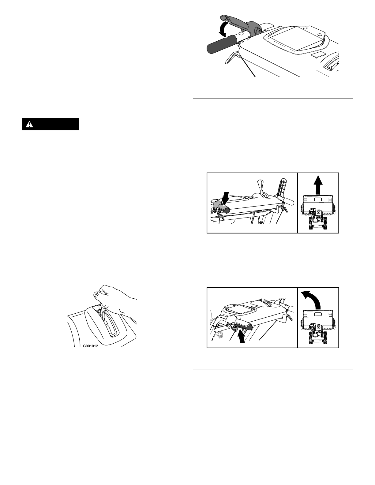
DrivingForward
1.Placethespeedselectorlevertothedesired
forwardposition,makingsurethatitlocksinthe
notch(Figure13).
g001012
Figure13
Note:Ifthegroundspeedistoofast,debrisor
snowwillpileupinfrontofthebroomcausing
thebroomtoplowinsteadofsweep.Thiscan
damagethebristlesandthedriveline.
2.Slowlysqueezethetraction-drivelevertothe
lefthandle(Figure14).
Note:Holddownthetraction-driveleveragainst
thehandletoengagethetractiondriveforboth
wheels.
g326524
Figure14
3.Tostopthetractiondrive,releasethe
traction-drivelever.
4.Usethewheelclutchesleversasfollows:
Note:
•Todrivestraight,squeezethetraction-drive
leverbutdonotsqueezethewheel-clutch
levers(Figure15).
g326528
Figure15
•Toturnleft,squeezethetraction-drivelever
andsqueezetheleftwheel-clutchlever
(Figure16).
g326521
Figure16
Note:Whenyoucompletetheturn,release
thewheel-clutchlever.Thetractiondrive
engagesbothwheels.
•Toturnright,squeezethetraction-drivelever
andsqueezetherightwheel-clutchlever
(Figure17).
13
g326522
Figure17
Note:Whenyoucompletetheturn,release
thewheel-clutchlever.Thetractiondrive
engagesbothwheels.
•Momentarilysqueezeandreleasetheleft
orrightwheel-clutchlevertomakesteering
adjustmentsandkeepthemachinemoving
inastraightline,especiallyindeepsnow.
5.Toshutoffthetractiondrive,releasethe
traction-drivelever.
DrivingtheMachineRearward
1.Placethespeed-selectorleverintothedesired
reverse-speedrange,makingsurethatthe
speedselectorlocksinthenotch.
2.Tomoverearward,engagethetractiondrive
andslowlysqueezethelefttractionlevertothe
handle.
Note:Momentarilysqueezingandreleasingthe
leftorrightwheel-clutchleverallowsforsteering
adjustmentstokeepthemachinegoingina
straightline.
Note:Toturnright,squeezetheright
wheel-clutchlevertowardthehandle.This
disengagesthedrivetotherightwheelwhilethe
leftwheelcontinuesdriving,andthemachine
turnstotheright.
Note:Similarly,squeezingtheleftwheel-clutch
leverturnsthemachinetotheleft.
Note:Squeezingbothwheel-clutchlevers
simultaneouslydisengagesthedrivetobothwheels.
Thisenablesyoutomovethemachinerearward
withoutstoppingtoshiftitintoareversegear.Italso
allowsyoutomaneuverandtransportthemachine
moreeasilywhentheengineisnotrunning.
PivotingtheMachinewiththe
EngineShutoff
Squeezebothwheel-clutchleverssimultaneouslyand
pivotthemachine(Figure18).
g326520
Figure18
OperatingtheBroom
DANGER
Whenthemachineisinoperation,contact
withrotatingormovingpartswillseverely
injurehandsandfeet.
•Beforeadjusting,cleaning,inspecting,
troubleshooting,orrepairingthemachine,
shutofftheengineandwaitforallmoving
partstostop.Disconnectthewirefrom
thesparkplugandkeepitawayfromthe
plugtopreventsomeonefromaccidentally
startingtheengine.
•Staybehindthehandlesandawayfromthe
broomwhileoperatingthemachine.
•Keepface,hands,feet,andanyother
partofyourbodyorclothingawayfrom
concealed,moving,orrotatingparts.
14
WARNING
Contactwitharotatingbroomcanresult
inseriouspersonalinjuryordeathtothe
operatororbystanders.
•Toremoveanobstructionfromthebroom;
refertoClearingaCloggedBroom(page
16).
•Donotoperatethemachineifthebroom
driveleverisnotfunctioningproperly.
ContactyourAuthorizedServiceDealer.
WARNING
Therotatingbroomcanthrowstonesand
otherforeignobjects,causingserious
personalinjurytoyouorbystanders.
•Keeptheworkingareaclearandfreeofall
objectsthatthebroomcouldpickupand
throw.
•Keepallchildrenandpetsawayfromthe
areaofoperation.
CAUTION
Whenthebroomisengaged,itmaydrivethe
machineinthereversedirection.Ifthebroom
heightisadjustedtoolow,themachinemay
movemoreforcefullyinthereversedirection,
causinginjuryand/orpropertydamage.
Carefullycheckthebroomheightandadjust
itproperlyorcontactyourAuthorizedService
Dealer.
1.SettheenginethrottletotheFASTposition.
2.Placethespeedselectorleverintothedesired
positionandslowlysqueezethelefthand
tractiondrivelever.
Important:Makesurethatthetractiondrive
isengagedbeforeoperatingthebroom;
otherwise,thebroommaydrivethemachine
inthereversedirection.
3.Engagethebroombyslowlysqueezingtheright
broomlevertothehandle(Figure19).
g326523
Figure19
•Iftheengineslowsdownunderaloadorthe
wheelsslip,shiftthemachineintoalower
gear.
•Ifthefrontofthemachineridesup,shift
themachineintoalowergear.Ifthefront
continuestorideup,liftthehandles.
4.Tostopthebroom,releasetherightlever.
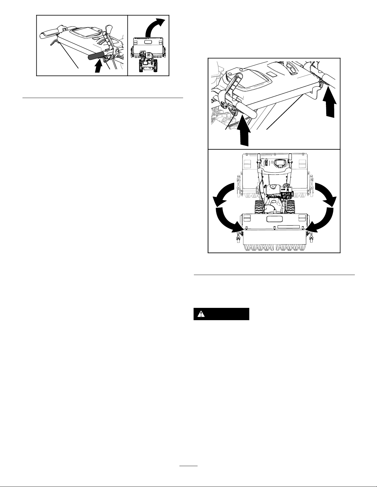
AdjustingtheBroomSide
Angle
1.Disengagethebroomandshutofftheengine.
2.Waitforallmovingpartstostop.
3.Pushtheleverdownwiththethumbofyourright
hand(Figure20).
g326519
Figure20
4.Squeezetheleftwheel-clutchlevertothehandle
(Figure20)andpushthebroomhousingto
followingpositions.
15
•19°totheleft
•Straightahead
•19°totheright
5.Oncethebroomispositioned,releasethe
broomanglelever.
Important:Ensurethatthebroomlocksinto
placeatoneofthe3positions.
6.Releasetheleftwheel-clutchlever.
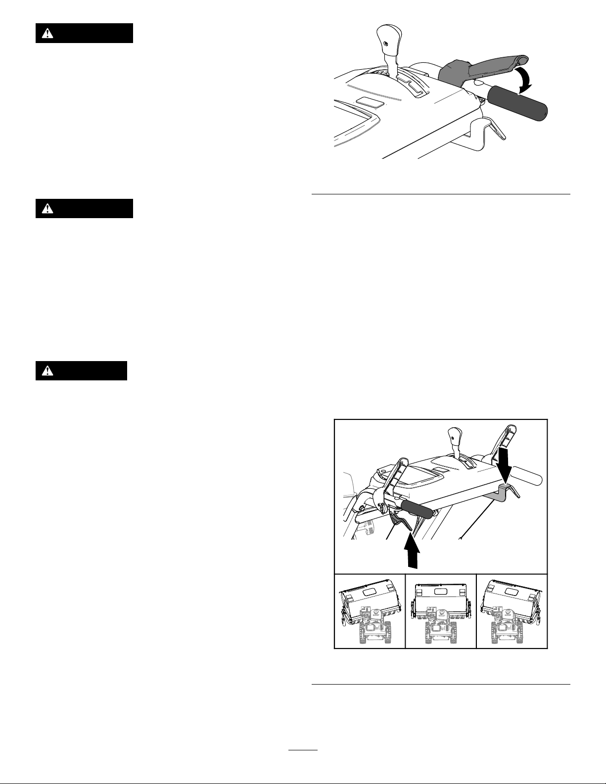
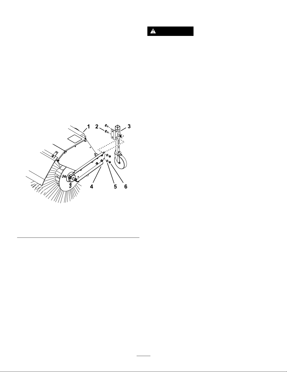
UsingtheAlternateCaster
Location
Whenworkinginsnow,movethecastersfromthe
frontofthebroomarmtothebackthebroomhood
(Figure21).
g326877
Figure21
1.Broomhood4.Broomarm
2.Carriagebolt5.Washer
3.Casterbracket6.Locknut
1.Supportthebroom.
2.Removethe2locknuts,2washers,and2
carriagebolts(Figure21)thatsecurethecaster
brackettothebroomarm.
3.Atthebackofthebroomhood,aligntheholesin
thecasterbracketwiththeholesontheinboard
sideofthebroomarm(Figure21).
4.Securethecasterbrackettothebroomarmwith
the2locknuts,2washers,and2carriagebolts
(Figure21).
ClearingaCloggedBroom
WARNING
Therotatingbroomcouldcauseserious
injury.
Shutofftheengineandallowallrotatingparts
tostopbeforecleaningthebroom.
•Ifthebroombecomesclogged,stayinthe
operatingpositionandreleasethetraction-drive
lever.Whileengagingthebroom,pushdownon
thehandlestoraisethefrontofthemachinea
fewcentimeters(inches)offthepavement.Then
liftthehandlesquicklytobumpthefrontofthe
machineonthepavement.Repeatifnecessary.
•Ifyoucannotunclogthebroombybumpingthe
frontofthemachine,dothefollowing:
–Parkthemachineonlevelground.shutoffthe
engine,waitforallmovingpartstostop,and
disconnectthespark-plugwire.
–Sharpobjectscanbecomeentangledin
bristles.Useglovesandcautionwhen
removingforeignobjectsfromthebroom;do
notuseyourhands.
AfterOperation
AfterOperationSafety
GeneralSafety
•Neverstorethemachinewithfuelinthefuel
tankinsideabuildingwhereignitionsourcesare
present,suchashotwaterheaters,spaceheaters,
orclothesdryers.Allowtheenginetocoolbefore
storingthemachineinanyenclosure.
•Whenstoringthemachineformorethan30
days,refertotheStoragesectionforimportant
information.
•Whenoperatinginsnowyconditions,runthe
machineforafewminutesafterremovingsnowto
preventfreeze-upofthebroomandhousing.
•Whencleaning,repairing,orinspectingthe
machine,ensurethattherotarybroomandall
movingpartshavestopped.Disconnectthe
spark-plugwireandkeepitawayfromtheplugto
preventaccidentalstarting.
•Disengagethepowertotherotarybroomwhen
transportingorstoringthemachine.
16

PreventingFreeze-upafter
Use
•Insnowyandcoldconditions,somecontrolsand
movingpartsmayfreeze.Donotuseexcessive
forcewhentryingtooperatefrozencontrols.Ifyou
havedifcultyoperatinganycontrolorpart,start
theengineandletitrunforafewminutes.
•Afterusingthemachine,lettheenginerunfora
fewminutestopreventmovingpartsfromfreezing.
Engagethebroomtoclearanyremainingsnow
frominsidethehousing.Shutofftheengineand
waitforallmovingpartstostop,anddisconnect
thespark-plugwire.Removeallice,snow,orother
debrisfromthemachine.
•Connectthespark-plugwire.Withtheengine
switchintheOFFposition,pulltherecoil-starter
handleseveraltimestopreventtherecoilstarter
fromfreezingup.
TransportingtheMachine
WARNING
Usingrampsthatarenotstrongenoughor
properlysupportedtoloadthemachineonto
thetransportvehiclecouldbedangerous.The
rampscouldcollapse,causingthemachineto
fall,whichcouldcauseinjury.
•Useproperrampsthataresecuredtothe
truckortrailer.
•Keepyourfeetandlegsoutfromunderthe
machinewhenloadingandunloading.
PreparingtoTransportthe
Machine
Performthefollowingbeforetransportingthemachine:
•Closethefuel-shutoffvalve.
•Useaheavy-dutytrailertotransportthemachine.
Placethemachineineitheraforwardorreverse
gear,thenblockthewheels.
•Securelyfastenthemachinetothetrailerwith
straps,chains,cables,orropes.
•Ensurethatthetrailerhasallthenecessary
lightingandmarkingasrequiredbylaw.
17

Maintenance
Note:Determinetheleftandrightsidesofthemachinefromthenormaloperatingposition.
RecommendedMaintenanceSchedule(s)
MaintenanceService
IntervalMaintenanceProcedure
Aftertherst2hours•Checkthetractioncableadjustmentandcorrectitifnecessary.
•Checkthebroomdriveadjustmentandcorrectitifnecessary.
Aftertherst5hours•Changetheengineoil.
Beforeeachuseordaily
•Checktheengineoillevel.
•Checkthebroom-shaftshearpin.
•Checkforloosehardware.
Every50hours
•Cleanthefoampre-cleaner(morefrequentlyindustyconditions).
•Checkthetireairpressure.
•Checktheconditionofthebelts.
Every100hours
•Lubricatethebroom-angle-lockpin.
•Changetheengineoil(morefrequentlyinsevereconditions).
•Checkthesparkplug.
Every200hours•Replacethefoampre-cleaner.
Every300hours•Replacethepaperairlter(morefrequentlyindustyconditions).
Yearly
•Lubricatethehexshaft.
•Checkthetractioncableadjustmentandcorrectitifnecessary.
•Checkthebroomdriveadjustmentandcorrectitifnecessary.
Yearlyorbeforestorage
•Drainthefuelsystemandruntheengineoutthefuelattheendoftheoperating
season.
•Checkthetireairpressure.
Important:Refertoyourengineowner'smanualforadditionalmaintenanceprocedures.Forengine
adjustments,repairs,orwarrantyservicenotcoveredinthismanual,contacttheauthorizedengine
servicedealer.
MaintenanceSafety
Readthefollowingsafetyprecautionsbefore
performinganymaintenanceonthemachine:
•Beforeservicing,adjusting,orcleaningthe
machine,shutofftheengineandwaitforall
movingpartstostop.Ifmajorrepairsareever
needed,contactyourAuthorizedServiceDealer.
•Alwaysweareyeprotectionwhileperformingan
adjustmentorrepairtoprotectyoureyesfrom
foreignobjectsthatthemachinemaythrow.
•Checkallfastenersatfrequentintervalsforproper
tightnesstoensurethatthemachineisinsafe
workingcondition.
•Donotchangethegovernorsettingsontheengine.
•PurchaseonlygenuineTororeplacementparts
andaccessories.
PreparingforMaintenance
1.Movethemachinetoalevelsurface.
2.Shutofftheengineandallowittocool.
3.Disconnectthespark-plugwirefromthespark
plugandkeepthewireawayfromtheplug,to
preventaccidentalstarting(Figure22).
18
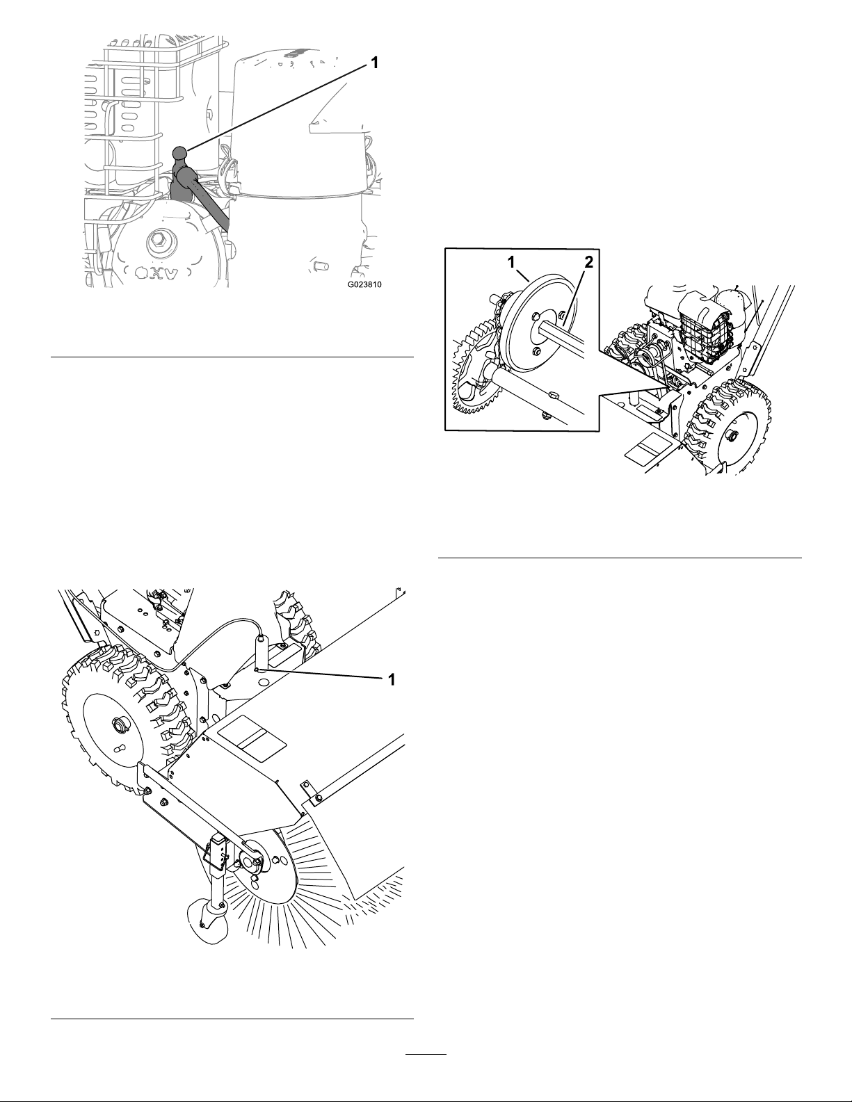
g023810
Figure22
1.Spark-plugwire
Lubrication
LubricatingtheBroom-Angle-Lock
PinandtheHexShaft
ServiceInterval:Every100hours
Yearly
1.Lubricatethebroom-angle-lockpinttingwith
No.2lithiumgrease(Figure23).
g325097
Figure23
1.Broom-angle-lockpin
2.Removethebeltcoverandtheengineshield.
3.Movethespeed-selectorlevertotheR2position.
4.Dipalong,clean,small-tippedpaintbrushin
automotiveengineoilandlightlylubricatethe
hexshaft(Figure24).
Important:Donotgetoilontherubber
wheelorthealuminumfriction-driveplateas
thetractiondrivewillslip(Figure24).
Note:Rockthemachineforwardandrearward
torotatethehexshaft.
g325104
Figure24
1.Aluminumfriction-drive
plate
2.Hexshaft
5.Movethespeedselectorlevertoposition6.
6.Lubricatetheotherendofthehexshaft.
7.Movethespeedselectorleverforwardand
rearwardafewtimes.
8.Installthebeltcoverandtheengineshield.
EngineMaintenance
ServicingtheAirCleaner
ServiceInterval:Every50hours—Cleanthefoam
pre-cleaner(morefrequentlyin
dustyconditions).
Every200hours—Replacethefoam
pre-cleaner.
Every300hours—Replacethepaperairlter
(morefrequentlyindustyconditions).
Important:Donotoperatetheenginewithoutthe
airlterassembly;extremeenginedamagemay
occur.
1.Releasethelatchesonthecoverfortheair
cleaner.
19
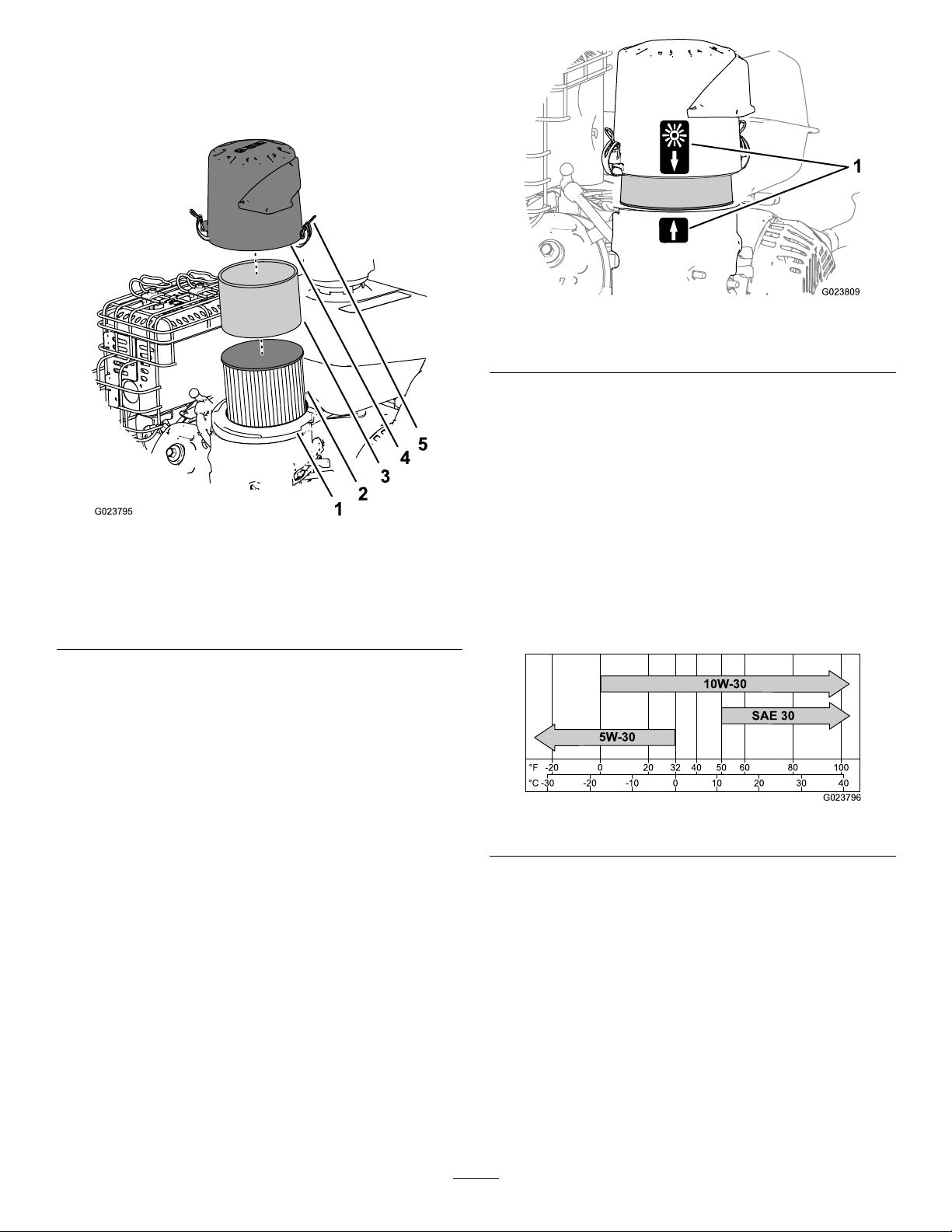
2.Removethecoverandcleanitthoroughly
(Figure25).
Note:Becarefultopreventdirtanddebrisfrom
fallingintothebase.
g023795
Figure25
1.Air-lterbase4.Cover
2.Paperairlter5.Latchontheair-cleaner
cover(2)
3.Foampre-cleaner
3.Removethefoampre-cleaner,washitwitha
milddetergentandwater,andthenblotitdry
(Figure25).
4.Removeandinspectthepaperairlter(Figure
25);discarditifitisexcessivelydirty.
Important:Donottrytocleanapaperlter.
5.Wipedirtawayfromthebaseandthecoverwith
amoistrag.
Note:Becarefultopreventdirtanddebrisfrom
enteringtheairductleadingtothecarburetor.
6.Installthefoampre-cleanerontothepaperair
lter(Figure25).
Note:Useanewpaperairlterifyoudiscarded
theoldone.
7.Installtheairlterassemblytotheair-lterbase
(Figure25).
8.Alignthearrowdecalontheair-cleanercover
andthearrowdecalonthebase(Figure26).
g023809
Figure26
1.Alignment-arrowdecal(normalambientairpositionshown)
9.Securetheair-ltercovertothebasewiththe
latches.
CheckingtheEngine-OilLevel
ServiceInterval:Beforeeachuseordaily
EngineOilType:T oro4–CyclePremiumEngineOil
Usehigh-qualitydetergentoils(includingsynthetic)
ofAPI(AmericanPetroleumInstitute)serviceclass
SJorhigher.Selecttheviscositybasedontheair
temperatureattimeofoperationasshowninthetable
below.
g023796
Figure27
Checktheoillevelwhentheengineiscold.
1.Cleantheareaaroundthedipstick.
2.Removethedipstickandreadtheoillevel
(Figure28).
20
Table of contents
Other Toro Floor Machine manuals


