Toro Workman GTX User manual

Form No. 16224SL Rev C
Workman®GTX Gasoline
Original Instructions (EN)

©
THE TORO COMPANY 2020
This document and all information contained herein is the sole property of The Toro Company (and/or its affiliated companies). No
intellectual property rights are granted by the delivery of this document or the disclosure of its content. This document shall not be
reproduced by a third party without the express written consent of The Toro Company (and/or the appropriate affiliated company).
Revision History
Revision
Date
Description
--
2016
Initial Issue.
A
03/2018
Incorporated EFI information and procedures.
Added revision history.
B
02/2020
Updated torque values.
C
05/2020
Updated Chassis and Electrical Drawings chapters.

Reader Comments
The Toro Company Technical Assistance Center maintains a continuous effort to improve the quality
and usefulness of its publications. To do this effectively, we encourage user feedback.
Please comment on the completeness, accuracy, organization, usability, and readability of this manual
by an e-mail to [email protected]
or Mail to:
Technical Publication Manager, Commercial
The Toro Company
8111 Lyndale Avenue South
Bloomington, MN 55420-1196
Phone: +1 952-887-8495

NOTES _

Part No. 16224SL (Rev. C)
Service Manual
WorkmanRGTX Gasoline
Preface
The purpose of this publication is to provide the service
technician with information for troubleshooting, testing
and repair of major systems and components on the
Workman GTX Gasoline vehicle.
REFER TO THE OPERATOR’S MANUAL FOR OPER-
ATING, MAINTENANCE AND ADJUSTMENT IN-
STRUCTIONS. For reference, insert a copy of the
Operator’s Manual and Parts Catalog for your machine
into Chapter 2 of this service manual. Additional copies
of the Operator’s Manual and Parts Catalog are avail-
able on the internet at www.Toro.com.
The Toro Company reserves the right to change product
specifications or this publication without notice.
This safety symbol means DANGER, WARNING,
or CAUTION, PERSONAL SAFETY INSTRUC-
TION. When you see this symbol, carefully read
the instructions that follow. Failure to obey the
instructions may result in personal injury.
NOTE: ANOTE will give general information about the
correct operation, maintenance, service, testing or re-
pair of the machine.
IMPORTANT: The IMPORTANT notice will give im-
portant instructions which must be followed to pre-
vent damage to systems or components on the
machine.
EThe Toro Company -- 2016, 2018, 2020

Workman GTX Gasoline
This page is intentionally blank.

Workman GTX Gasoline
Table Of Contents
Chapter 1 -- Safety
Safety Instructions 1 -- 2..........................
Jacking and Other Instructions 1 -- 4...............
Safety and Instruction Decals 1 -- 6................
Chapter 2 -- Product Records and Maintenance
Product Records 2 -- 1...........................
Maintenance 2 -- 1...............................
Equivalents and Conversions 2 -- 2................
Torque Specifications 2 -- 3.......................
Chapter 3 -- Gasoline Engine
General Information 3 -- 2........................
Specifications 3 -- 4..............................
Adjustments 3 -- 5...............................
Service and Repairs 3 -- 6........................
KOHLER COMMAND PRO CH260--CH440 SERVICE
MANUAL
KOHLER COMMAND PRO EFI ECH440 & ECH440LE
SERVICE MANUAL
Chapter 4 -- Drive Train
General Information 4 -- 1........................
Specifications 4 -- 2..............................
Drive Train Operation 4 -- 3.......................
Special Tools 4 -- 6..............................
Adjustments 4 -- 7...............................
Service and Repairs 4 -- 10.......................
Chapter 5 -- Electrical System
General Information 5 -- 2........................
Electrical Drawings 5 -- 2.........................
Special Tools 5 -- 4..............................
Troubleshooting 5 -- 6............................
Electrical System Quick Checks 5 -- 8..............
Component Testing 5 -- 9.........................
Service and Repairs 5 -- 26.......................
ADVANCED MOTORS & DRIVES STARTER/
GENERATOR TROUBLESHOOTING GUIDE
Chapter 6 -- Chassis
General Information 6 -- 1........................
Specifications 6 -- 2..............................
Special Tools 6 -- 2..............................
Troubleshooting 6 -- 3............................
Adjustments 6 -- 6...............................
Service and Repairs 6 -- 9........................
Chapter 7 -- Electrical Drawings
Electrical Drawing Designations 7 -- 2..............
Electrical Schematic 7 -- 3........................
Circuit Diagrams 7 -- 8...........................
Electrical Harnesses 7 -- 11.......................
SafetyProduct Records
and Maintenance
Drive TrainElectrical
System
Electrical
Drawings Chassis Gasoline
Engine

Workman GTX Gasoline
This page is intentionally blank.

Workman GTX Gasoline Page 1 −1 Safety
Chapter 1
Safety
Table of Contents
SAFETY INSTRUCTIONS 2......................
Supervisor’s Responsibilities 2.................
Before Operating 2............................
While Operating 3............................
Maintenance and Service 3....................
JACKING AND OTHER INSTRUCTIONS 4........
Jacking Vehicle 4.............................
Transporting Vehicle 4.........................
Towing Vehicle 4..............................
Transaxle Neutral Position 5...................
SAFETY AND INSTRUCTION DECALS 6..........
Safety

Workman GTX GasolinePage 1 −2Safety
Safety Instructions
The Workman GTX vehicles are designed and tested to
offer safe service when operated and maintained pro-
perly. Although hazard control and accident prevention
partially are dependent upon the design and configura-
tion of the machine, these factors are also dependent
upon the awareness, concern and proper training of the
personnel involved in the operation, transport, mainte-
nance and storage of the machine. Improper use or
maintenance of the machine can result in injury or
death.
This safety symbol means DANGER, WARNING,
or CAUTION, PERSONAL SAFETY INSTRUC-
TION. When you see this symbol, carefully read
the instructions that follow. Failure to obey the
instructions may result in personal injury.
WARNING
To reduce the potential for injury or death, com-
ply with the following safety instructions.
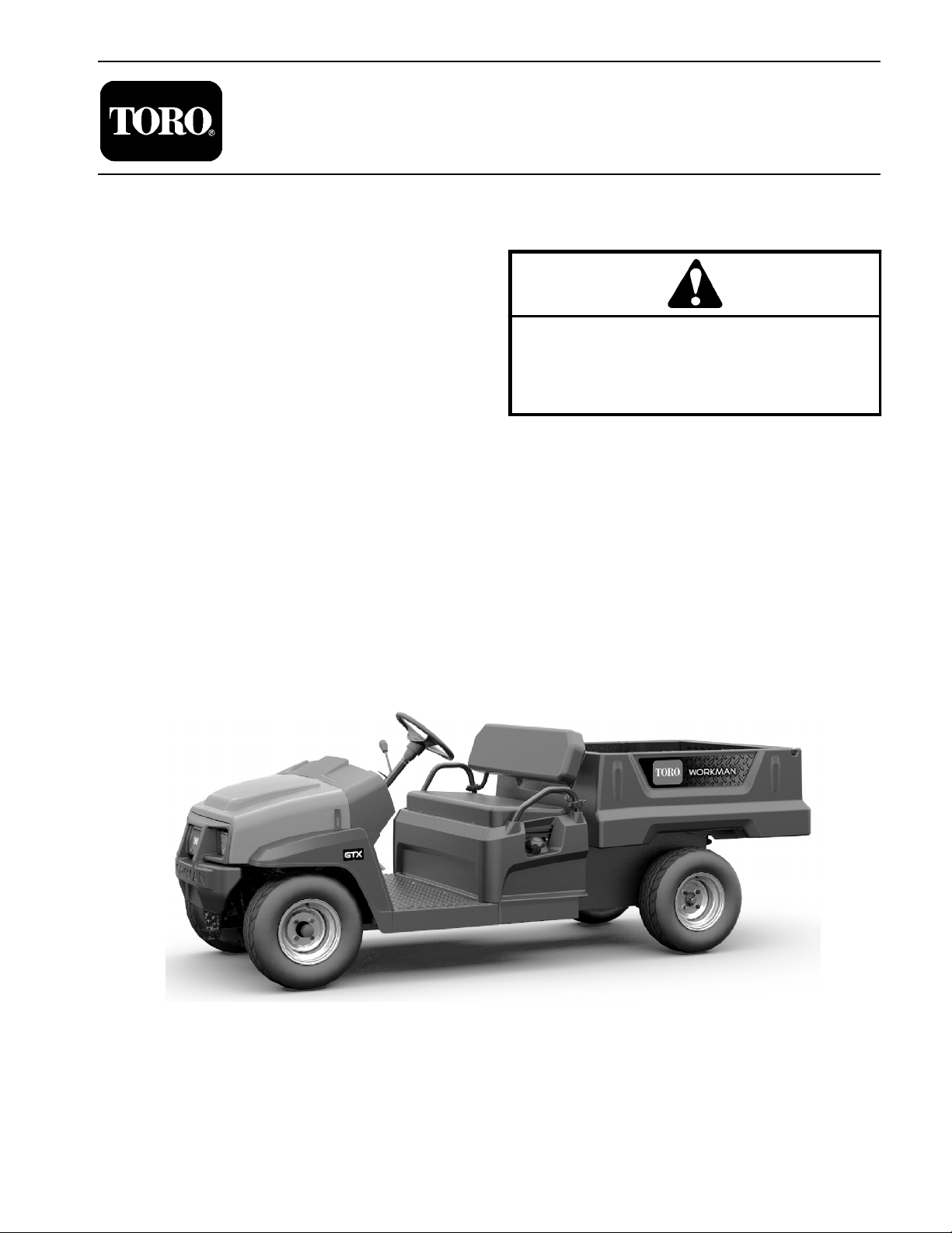
WARNING
The Workman GTX is an off−highway vehicle
only. It is not designed, equipped or manufac-
tured for use on public streets, roads or high-
ways.
Supervisor’s Responsibilities
1. Make sure operators are thoroughly trained and fa-
miliar with the Operator’s Manual and all labels on the
vehicle.
2. Be sure to establish your own special procedures
and work rules for unusual operating conditions (e.g.
slopes too steep for vehicle operation).
Before Operating
1. Read and understand the contents of the Operator’s
Manual and Operator’s DVD before starting and operat-
ing the vehicle. Become familiar with the controls and
know how to stop the vehicle and engine quickly. Addi-
tional copies of the Operator’s Manual are available on
the internet at www.Toro.com.
2. Keep all shields, safety devices and decals in place.
If a shield, safety device or decal is defective, illegible or
damaged, repair or replace it before operating the ve-
hicle. Also, tighten any loose nuts, bolts or screws to en-
sure vehicle is in safe operating condition.
3. Since fuel used in Workman vehicles is highly flam-
mable, handle it carefully:
A. Store fuel in containers specifically designed for
this purpose.
B. Do not remove vehicle fuel tank cap while engine
is hot or running.
C. Do not smoke while handling fuel.
D. Fill fuel tank outdoors and only to within an inch of
the top of the tank, not the filler neck. Do not overfill
the fuel tank.
E. Clean up any spilled fuel.

Workman GTX Gasoline Page 1 −3 Safety
While Operating
1. Sit on the operator seat when starting and operating
the vehicle.
2. When the vehicle is stationary, apply the parking
brake to prevent the vehicle from unexpected move-
ment. Make sure to release parking brake before driving
the vehicle.
3. The engine can be started by rotating the key switch
to the START position or by turning the key switch to the
ON position and depressing the accelerator pedal.
4. Do not run engine in a confined area without ade-
quate ventilation. Exhaust fumes are hazardous and
could possibly be deadly.
5. Do not touch engine, muffler or exhaust pipe while
engine is running or soon after it is stopped. These areas
could be hot enough to cause burns.
6. Before getting off the seat:
A. Stop movement of the vehicle.
B. Turn key switch to OFF and wait for all machine
movement to stop.
C. Remove key from key switch.
D. Apply parking brake.
7. If vehicle is parked on incline, chock or block the
wheels after getting off the vehicle.
Maintenance and Service
1. Before servicing or making adjustments, turn engine
and all accessories OFF, release pressure from acceler-
ator pedal, allow engine to stop, set parking brake and
remove key from the key switch.
2. Make sure vehicle is in safe operating condition by
keeping all nuts, bolts and screws tight.
3. Never store the vehicle or fuel container inside
where there is an open flame, such as near a water heat-
er or furnace.
4. To reduce potential fire hazard, keep engine area
free of excessive grease, grass, leaves and dirt.
5. If engine must be running to perform maintenance or
an adjustment, keep clothing, hands, feet and other
parts of the body away from moving parts. Keep by-
standers away.
6. Do not overspeed the engine by changing governor
setting. To assure safety and accuracy, check maximum
engine speed. The maximum engine speed for the
Workman GTX is 3750 RPM.
7. Shut engine off before checking or adding oil to the
engine crankcase.
8. Disconnect battery before servicing the vehicle. Dis-
connect negative (−) battery cable first and positive (+)
cable last. If battery voltage is required for troubleshoot-
ing or test procedures, temporarily connect the battery.
Reconnect positive (+) cable first and negative (−) cable
last.
9. Battery acid is poisonous and can cause burns.
Avoid contact with skin, eyes and clothing. Protect your
face, eyes and clothing when working with a battery.
10.Battery gases can explode. Keep cigarettes, sparks
and flames away from the battery.
11. If major repairs are ever needed or assistance is de-
sired, contact an Authorized Toro Distributor.
12.To assure optimum performance and continued
safety of the vehicle, use genuine Toro replacement
parts and accessories. Replacement parts and acces-
sories made by other manufacturers may result in non-
conformance with safety standards, and the warranty
may be voided.
13.When raising the vehicle to change tires or to per-
form other service, use correct blocks, hoists and jacks.
Make sure vehicle is parked on a solid level surface such
as a concrete floor. Prior to raising the vehicle, remove
any attachments that may interfere with the safe and
proper raising of the vehicle. Always chock or block
wheels. Use appropriate jack stands to support the
raised vehicle. If the vehicle is not properly supported by
jack stands, the vehicle may move or fall, which may re-
sult in personal injury (see Jacking Instructions in this
section).
14.Make sure to dispose of potentially harmful waste
(e.g. fuel, oil, engine coolant, filters, battery) in an envir-
onmentally safe manner. Follow all local codes and reg-
ulations when recycling or disposing of waste.
Safety

Workman GTX GasolinePage 1 −4Safety
Jacking and Other Instructions
Jacking Vehicle
DANGER
POTENTIAL HAZARD
•A vehicle that is not properly supported
may become unstable.
WHAT CAN HAPPEN
•The vehicle may move or fall. Personal
injury or damage to the machine may result.
HOW TO AVOID THE HAZARD
•Make sure vehicle is parked on a solid level
surface, such as a concrete floor.
•Make sure engine is off and key is removed
from the key switch before getting off the
vehicle.
•Before raising the vehicle, remove any
attachments that may interfere with the safe
and proper raising of the vehicle.
•Always chock or block wheels to prevent
the vehicle from rolling.
•Do not start vehicle while it is on jack
stands without placing transaxle in neutral.
•Make sure proper hoists, jacks and jack
stands are used to raise and support the
vehicle.
Jacking Locations
1. Jack front of the vehicle on the front of the frame be-
hind the towing tongue (Fig. 1).
2. Jack rear of the vehicle under each rear axle tube. Do
not jack vehicle below the transaxle case (Fig. 2).
1. Front of frame 2. Towing tongue
Figure 1
21
1. Rear axle tube 2. Transaxle case
Figure 2
21
1
Transporting Vehicle
When moving the vehicle long distances, use a trailer or
flatbed truck. Make sure vehicle is secured to the trailer
properly. Also, make sure to secure seats to vehicle dur-
ing transport. Refer to Operator’s Manual for transport
information.
Towing Vehicle
IMPORTANT: Frequent or long distance towing of
the Workman GTX is not recommended.
In case of emergency, the vehicle can be towed for a
short distance. Refer to Operator’s Manual for towing
information.
IMPORTANT: If vehicle is towed, make sure that
transaxle is in the NEUTRAL position, parking brake
is released, key switch is in the OFF position, and
key is removed from switch. Also, secure seats to
vehicle.

Workman GTX Gasoline Page 1 −5 Safety
Transaxle Neutral Position
When performing routine maintenance and/or engine
testing, the transaxle must be shifted into the neutral
position.
1. Park machine on a level surface, stop engine, set
parking brake and remove key from the key switch.
2. Move shift lever to the neutral position (Fig. 3).
3. Make sure transaxle is in the neutral position by ro-
tating the secondary clutch (Fig. 4). The rear tires should
not rotate as the secondary clutch is rotated. If tire rota-
tion does occur, see Adjust Shift Cable in the Adjustment
section of Chapter 5 −Drive Train.
1. Shift lever (in neutral)
2. Forward position
3. Reverse position
Figure 3
1
2
3
1. Secondary clutch
2. Primary clutch
3. Rear wheel
Figure 4
21
3
3
Safety

Workman GTX GasolinePage 1 −6Safety
Safety and Instruction Decals
Numerous safety and instruction decals are affixed to
your Workman GTX. If any decal becomes illegible or
damaged, install a new decal. Part numbers are listed
in the Parts Catalog. Order replacement decals from
your Authorized Toro Distributor.

Workman GTX Page 2 −1 Product Records and Maintenance
Chapter 2
Product Records and Maintenance
Table of Contents
PRODUCT RECORDS 1.........................
MAINTENANCE 1..............................
EQUIVALENTS AND CONVERSIONS 2...........
Decimal and Millimeter Equivalents 2............
U.S. to Metric Conversions 2...................
TORQUE SPECIFICATIONS 3...................
Fastener Identification 3.......................
Using a Torque Wrench with an Offset Wrench 3..
Standard Torque for Dry, Zinc Plated and
Steel Fasteners (Inch Series) 4...............
Standard Torque for Dry, Zinc Plated and
Steel Fasteners (Metric Fasteners) 5..........
Other Torque Specifications 6..................
Conversion Factors 6.........................
Product Records
Insert Operator’s Manual and Parts Catalog for your
Workman at the end of this chapter. Additionally, if any
optional equipment or accessories have been installed
to your machine, insert the Installation Instructions, Op-
erator’s Manuals and Parts Catalogs for those options
at the end of this chapter.
Maintenance
Maintenance procedures and recommended service in-
tervals for your Workman are covered in the Operator’s
Manual. Refer to that publication when performing regu-
lar equipment maintenance.
Product Records
and Maintenance

0.09375
Workman GTXPage 2 −2Product Records and Maintenance
Equivalents and Conversions

Workman GTX Page 2 −3 Product Records and Maintenance
Torque Specifications
Recommended fastener torque values are listed in the
following tables. For critical applications, as determined
by Toro, either the recommended torque or a torque that
is unique to the application is clearly identified and spe-
cified in this Service Manual.
These Torque Specifications for the installation and
tightening of fasteners shall apply to all fasteners which
do not have a specific requirement identified in this Ser-
vice Manual. The following factors shall be considered
when applying torque: cleanliness of the fastener, use
of a thread sealant (e.g. Loctite), degree of lubrication
on the fastener, presence of a prevailing torque feature
(e.g. Nylock nut), hardness of the surface underneath
the fastener’s head or similar condition which affects the
installation.
As noted in the following tables, torque values should be
reduced by 25% for lubricated fasteners to achieve
the similar stress as a dry fastener. Torque values may
also have to be reduced when the fastener is threaded
into aluminum or brass. The specific torque value
should be determined based on the aluminum or brass
material strength, fastener size, length of thread en-
gagement, etc.
The standard method of verifying torque shall be per-
formed by marking a line on the fastener (head or nut)
and mating part, then back off fastener 1/4 of a turn.
Measure the torque required to tighten the fastener until
the lines match up.
Fastener Identification
Figure 1
Grade 1 Grade 5 Grade 8
Inch Series Bolts and Screws
Figure 2
Class 8.8 Class 10.9
Metric Bolts and Screws
Using a Torque Wrench with an Offset Wrench
Use of an offset wrench (e.g. crowfoot wrench) will affect
torque wrench calibration due to the effective change of
torque wrench length. When using a torque wrench with
an offset wrench, multiply the listed torque recommen-
dation by the calculated torque conversion factor (Fig.
3) to determine proper tightening torque. Tightening
torque when using a torque wrench with an offset
wrench will be lower than the listed torque recommen-
dation.
Example: The measured effective length of the torque
wrench (distance from the center of the handle to the
center of the square drive) is 18”.
The measured effective length of the torque wrench with
the offset wrench installed (distance from the center of
the handle to the center of the offset wrench) is 19”.
The calculated torque conversion factor for this torque
wrench with this offset wrench would be 18 / 19 = 0.947.
If the listed torque recommendation for a fastener is
from 76 to 94 ft−lb, the proper torque when using this
torque wrench with an offset wrench would be from 72
to 89 ft−lb.
Figure 3
(effective length of
torque wrench)
TORQUE CONVERSION FACTOR = A / B
A
B
(effective length of torque
Torque wrenchOffset wrench
wrench + offset wrench)
Product Records
and Maintenance

Workman GTXPage 2 −4Product Records and Maintenance
Standard Torque for Dry, Zinc Plated and Steel Fasteners (Inch Series)
Thread Size
Grade 1, 5 &
8 with Thin
Height Nuts
SAE Grade 1 Bolts, Screws, Studs &
Sems with Regular Height Nuts
(SAE J995 Grade 2 or Stronger Nuts)
SAE Grade 5 Bolts, Screws, Studs &
Sems with Regular Height Nuts
(SAE J995 Grade 2 or Stronger Nuts)
SAE Grade 8 Bolts, Screws, Studs &
Sems with Regular Height Nuts
(SAE J995 Grade 5 or Stronger Nuts)
in−lb in−lb N−cm in−lb N−cm in−lb N−cm
# 6 −32 UNC
10 + 2 13 + 2 147 + 23
15 + 2 170 + 20 23 + 2 260 + 20
# 6 −40 UNF 17 + 2 190 + 20 25 + 2 280 + 20
# 8 −32 UNC
13 + 2 25 + 5 282 + 30
29 + 3 330 + 30 41 + 4 460 + 45
# 8 −36 UNF 31 + 3 350 + 30 43 + 4 485 + 45
# 10 −24 UNC
18 + 2 30 + 5 339 + 56
42 + 4 475 + 45 60 + 6 675 + 70
# 10 −32 UNF 48 + 4 540 + 45 68 + 6 765 + 70
1/4 −20 UNC 48 + 7 53 + 7 599 + 79 100 + 10 1125 + 100 140 + 15 1580 + 170
1/4 −28 UNF 53 + 7 65 + 10 734 + 113 115 + 10 1300 + 100 160 + 15 1800 + 170
5/16 −18 UNC 115 + 15 105 + 17 1186 + 169 200 + 25 2250 + 280 300 + 30 3390 + 340
5/16 −24 UNF 138 + 17 128 + 17 1446 + 192 225 + 25 2540 + 280 325 + 30 3670 + 340
ft−lb ft−lb N−mft−lb N−mft−lb N−m
3/8 −16 UNC 16 + 2 16 + 2 22 + 3 30 + 3 41 + 4 43 + 4 58 + 5
3/8 −24 UNF 17 + 2 18 + 2 24 + 3 35 + 3 47 + 4 50 + 4 68 + 5
7/16 −14 UNC 27 + 3 27 + 3 37 + 4 50 + 5 68 + 7 70 + 7 95 + 9
7/16 −20 UNF 29 + 3 29 + 3 39 + 4 55 + 5 75 + 7 77 + 7 104 + 9
1/2 −13 UNC 30 + 3 48 + 7 65 + 9 75 + 8 102 + 11 105 + 10 142 + 14
1/2 −20 UNF 32 + 3 53 + 7 72 + 9 85 + 8 115 + 11 120 + 10 163 + 14
5/8 −11 UNC 65 + 10 88 + 12 119 + 16 150 + 15 203 + 20 210 + 20 285 + 27
5/8 −18 UNF 75 + 10 95 + 15 129 + 20 170 + 15 230 + 20 240 + 20 325 + 27
3/4 −10 UNC 93 + 12 140 + 20 190 + 27 265 + 25 359 + 34 375 + 35 508 + 47
3/4 −16 UNF 115 + 15 165 + 25 224 + 34 300 + 25 407 + 34 420 + 35 569 + 47
7/8 −9 UNC 140 + 20 225 + 25 305 + 34 430 + 45 583 + 61 600 + 60 813 + 81
7/8 −14 UNF 155 + 25 260 + 30 353 + 41 475 + 45 644 + 61 660 + 60 895 + 81
NOTE: Reduce torque values listed in the table above
by 25% for lubricated fasteners. Lubricated fasteners
are defined as threads coated with a lubricant such as
oil, graphite or thread sealant such as Loctite.
NOTE: Torque values may have to be reduced when
installing fasteners into threaded aluminum or brass.
The specific torque value should be determined based
on the fastener size, the aluminum or base material
strength, length of thread engagement, etc.
NOTE: The nominal torque values listed above for
Grade 5 and 8 fasteners are based on 75% of the mini-
mum proof load specified in SAE J429. The tolerance is
approximately + 10% of the nominal torque value. Thin
height nuts include jam nuts.

Workman GTX Page 2 −5 Product Records and Maintenance
Standard Torque for Dry, Zinc Plated and Steel Fasteners (Metric Fasteners)
Thread Size
Class 8.8 Bolts, Screws and Studs with
Regular Height Nuts
(Class 8 or Stronger Nuts)
Class 10.9 Bolts, Screws and Studs with
Regular Height Nuts
(Class 10 or Stronger Nuts)
M5 X 0.8 57 + 5 in−lb 640 + 60 N−cm 78 + 7 in−lb 885 + 80 N−cm
M6 X 1.0 96 + 9 in−lb 1018 + 100 N−cm 133 + 13 in−lb 1500 + 150 N−cm
M8 X 1.25 19 + 2 ft−lb 26 + 3 N−m27 + 2 ft−lb 36 + 3 N−m
M10 X 1.5 38 + 4 ft−lb 52 + 5 N−m53 + 5 ft−lb 72 + 7 N−m
M12 X 1.75 66 + 7 ft−lb 90 + 10 N−m 92 +9 ft−lb 125 +12 N−m
M16 X 2.0 166 +15 ft−lb 225 + 20 N−m229 + 22 ft−lb 310 + 30 N−m
M20 X 2.5 325 + 33 ft−lb 440 + 45 N−m450 + 37 ft−lb 610 + 50 N−m
NOTE: Reduce torque values listed in the table above
by 25% for lubricated fasteners. Lubricated fasteners
are defined as threads coated with a lubricant such as
oil, graphite or thread sealant such as Loctite.
NOTE: Torque values may have to be reduced when
installing fasteners into threaded aluminum or brass.
The specific torque value should be determined based
on the fastener size, the aluminum or base material
strength, length of thread engagement, etc.
NOTE: The nominal torque values listed above are
based on 75% of the minimum proof load specified in
SAE J1199. The tolerance is approximately + 10% of the
nominal torque value.
Product Records
and Maintenance

Workman GTXPage 2 −6Product Records and Maintenance
Other Torque Specifications
SAE Grade 8 Steel Set Screws
Thread Size
Recommended Torque
Square Head Hex Socket
1/4 −20 UNC 140 + 20 in−lb 73 + 12 in−lb
5/16 −18 UNC 215 + 35 in−lb 145 + 20 in−lb
3/8 −16 UNC 35 + 10 ft−lb 18 + 3 ft−lb
1/2 −13 UNC 75 + 15 ft−lb 50 + 10 ft−lb
Thread Cutting Screws
(Zinc Plated Steel)
Type 1, Type 23 or Type F
Thread Size Baseline Torque*
No. 6 −32 UNC 20 + 5 in−lb
No. 8 −32 UNC 30 + 5 in−lb
No. 10 −24 UNC 38 + 7 in−lb
1/4 −20 UNC 85 + 15 in−lb
5/16 −18 UNC 110 + 20 in−lb
3/8 −16 UNC 200 + 100 in−lb
Wheel Bolts and Lug Nuts
Thread Size Recommended Torque**
7/16 −20 UNF
Grade 5
65 + 10 ft−lb 88 + 14 N−m
1/2 −20 UNF
Grade 5
80 + 10 ft−lb 108 + 14 N−m
M12 X 1.25
Class 8.8
80 + 10 ft−lb 108 + 14 N−m
M12 X 1.5
Class 8.8
80 + 10 ft−lb 108 + 14 N−m
** For steel wheels and non−lubricated fasteners.
Thread Cutting Screws
(Zinc Plated Steel)
Thread
Size
Threads per Inch
Baseline Torque*
Type A Type B
No. 6 18 20 20 + 5 in−lb
No. 8 15 18 30 + 5 in−lb
No. 10 12 16 38 + 7 in−lb
No. 12 11 14 85 + 15 in−lb
* Hole size, material strength, material thickness and fin-
ish must be considered when determining specific
torque values. All torque values are based on non−lubri-
cated fasteners.
Conversion Factors
in−lb X 11.2985 = N−cm N−cm X 0.08851 = in−lb
ft−lb X 1.3558 = N−mN−m X 0.7376 = ft−lb
Other manuals for Workman GTX
7
Table of contents
Other Toro Golf Car manuals