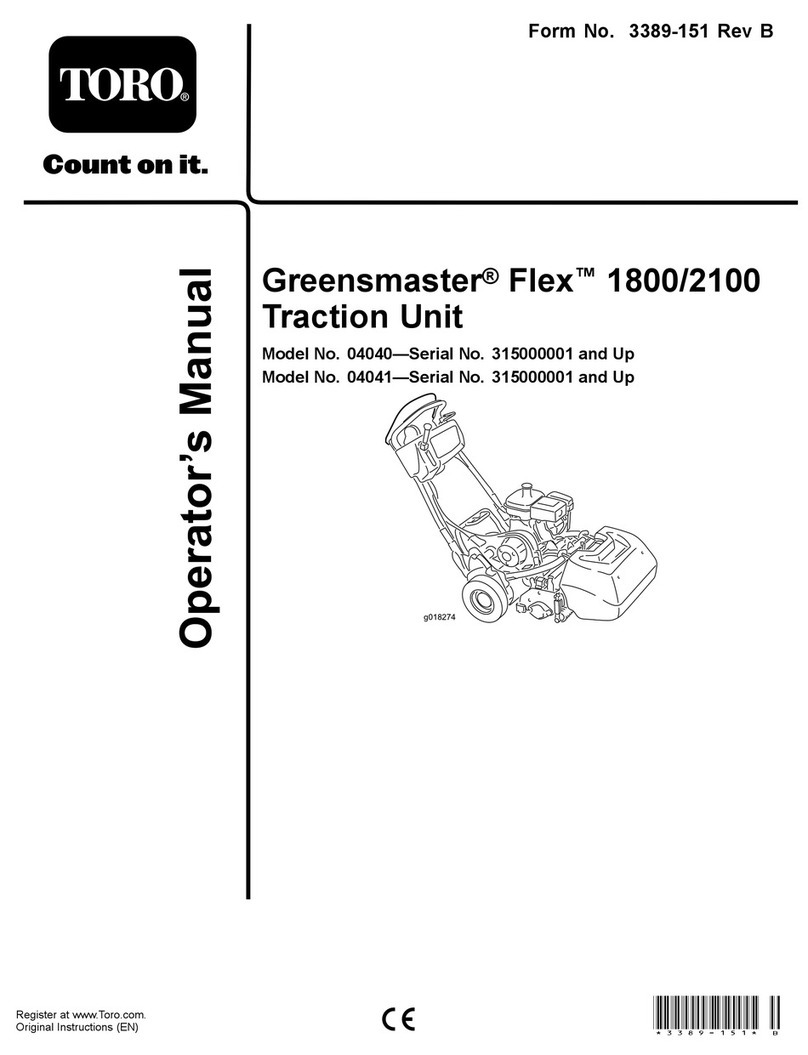
Toro 04510 Greensmaster 3300 TriFlex User manual

FormNo.3398-680RevA
Greensmaster®3300TriFlex®
TractionUnit
ModelNo.04510—SerialNo.316000001andUp
g014597
Registeratwww.Toro.com.
OriginalInstructions(EN)*3398-680*A

ThisproductcomplieswithallrelevantEuropeandirectives;
fordetails,pleaseseetheseparateproductspecicDeclaration
ofConformity(DOC)sheet.
WARNING
CALIFORNIA
Proposition65Warning
Thisproductcontainsachemicalorchemicals
knowntotheStateofCaliforniatocausecancer,
birthdefects,orreproductiveharm.
Theengineexhaustfromthisproduct
containschemicalsknowntotheStateof
Californiatocausecancer,birthdefects,
orotherreproductiveharm.
ThissparkignitionsystemcomplieswithCanadianICES-002.
ItisaviolationofCaliforniaPublicResourceCode
Section4442or4443touseoroperatetheengineonany
forest-covered,brush-covered,orgrass-coveredlandunless
theengineisequippedwithasparkarrester,asdenedin
Section4442,maintainedineffectiveworkingorderorthe
engineisconstructed,equipped,andmaintainedforthe
preventionofre.
Introduction
Thismachineisaride-on,reel-bladelawnmowerintended
tobeusedbyprofessional,hiredoperatorsincommercial
applications.Itisprimarilydesignedforcuttinggrasson
well-maintainedlawnsinparks,golfcourses,sportselds,
andoncommercialgrounds.Itisnotdesignedforcutting
brush,mowinggrassandothergrowthalongsidehighways,
orforagriculturaluses.
Readthisinformationcarefullytolearnhowtooperateand
maintainyourproductproperlyandtoavoidinjuryand
productdamage.Youareresponsibleforoperatingthe
productproperlyandsafely.
YoumaycontactTorodirectlyatwww.Toro.comforproduct
andaccessoryinformation,helpndingadealer,ortoregister
yourproduct.
Wheneveryouneedservice,genuineToroparts,oradditional
information,contactanAuthorizedServiceDealerorToro
CustomerServiceandhavethemodelandserialnumbersof
yourproductready.Figure1identiesthelocationofthe
modelandserialnumbersontheproduct.Writethenumbers
inthespaceprovided.
g014685
1
Figure1
1.Modelandserialnumberlocation
ModelNo.
SerialNo.
Thismanualidentiespotentialhazardsandhassafety
messagesidentiedbythesafety-alertsymbol(Figure2),
whichsignalsahazardthatmaycauseseriousinjuryordeath
ifyoudonotfollowtherecommendedprecautions.
Figure2
1.Safety-alertsymbol
Thismanualuses2wordstohighlightinformation.
Importantcallsattentiontospecialmechanicalinformation
andNoteemphasizesgeneralinformationworthyofspecial
attention.
©2015—TheToro®Company
8111LyndaleAvenueSouth
Bloomington,MN554202
Contactusatwww.Toro.com.
PrintedintheUSA
AllRightsReserved

Contents
Safety...........................................................................4
SafeOperatingPractices...........................................4
ToroMowerSafety..................................................5
SoundPowerLevel..................................................6
SoundPressureLevel...............................................6
Hand-ArmVibrationLevel......................................6
WholeBodyVibrationLevel....................................6
SafetyandInstructionalDecals.................................7
Setup...........................................................................11
1InstallingtheRollBar...........................................12
2InstallingtheSeat.................................................12
3InstallingtheSteeringWheel..................................12
4ActivatingandChargingtheBattery........................13
5InstallingtheOilCooler(optional).........................14
6InstallingtheGrass-BasketHooks..........................14
7InstallingtheCuttingUnits...................................15
8AddingRearWeight.............................................15
9InstallingEUDecals.............................................15
10ReducingtheTirePressure..................................15
11BurnishingtheBrakes.........................................15
ProductOverview.........................................................16
Controls...............................................................16
Specications........................................................19
Attachments/Accessories........................................19
Operation....................................................................20
ThinkSafetyFirst...................................................20
CheckingtheEngineOil..........................................20
FillingtheFuelTank...............................................21
CheckingtheHydraulic-FluidLevel..........................22
CheckingtheReel-to-BedknifeContact.....................23
CheckingtheTirePressure......................................23
CheckingtheTorqueoftheWheelNuts.....................23
BreakingintheMachine..........................................23
StartingandStoppingtheEngine..............................23
CheckingtheSafety-InterlockSystem........................24
CheckingtheLeakDetector.....................................25
InstallingandRemovingtheCuttingUnits.................26
SettingtheReelSpeed.............................................28
Mowing................................................................29
InspectingandCleaningafterMowing.......................30
DrivingtheMachinewithoutMowing.......................30
TransportingtheMachine........................................30
TowingtheMachine...............................................31
Maintenance.................................................................32
RecommendedMaintenanceSchedule(s)......................32
DailyMaintenanceChecklist....................................33
EngineMaintenance..................................................34
ServicingtheAirCleaner.........................................34
ChangingtheEngineOilandFilter...........................34
ReplacingtheSparkPlugs........................................35
FuelSystemMaintenance...........................................35
ReplacingtheFuelFilter..........................................35
InspectingtheFuelLinesandConnections.................35
ElectricalSystemMaintenance....................................36
ServicingtheBattery...............................................36
LocatingtheFuses..................................................36
DriveSystemMaintenance.........................................37
AdjustingtheTransmissionforNeutral.....................37
AdjustingtheTransportSpeed.................................37
AdjustingtheMowingSpeed....................................38
BrakeMaintenance....................................................38
AdjustingtheBrakes...............................................38
HydraulicSystemMaintenance....................................39
ChangingtheHydraulicFluidandFilter.....................39
CheckingtheHydraulicLinesandHoses....................39
CuttingUnitMaintenance...........................................40
BacklappingtheReels.............................................40
DiagnosticsSystem....................................................41
DiagnosingtheService-IndicatorLight......................41
Storage........................................................................41
3

Safety
Thismachinehasbeendesignedinaccordancewith
ENISO5395:2013andANSIB71.4-2012andmeetsthese
standardswhentheappropriateweightkitisadded.
Improperuseormaintenancebytheoperatororowner
canresultininjury.Toreducethepotentialforinjury,
complywiththesesafetyinstructionsandalwayspay
attentiontothesafetyalertsymbol(Figure2),which
meansCaution,Warning,orDanger—personalsafety
instruction.Failuretocomplywiththeinstructionmay
resultinpersonalinjuryordeath.
SafeOperatingPractices
Training
•ReadtheOperator'sManualandothertrainingmaterial.If
theoperator(s)ormechanic(s)cannotreadthemanualitis
theowner'sresponsibilitytoexplainthismaterialtothem.
•Becomefamiliarwiththesafeoperationoftheequipment,
operatorcontrols,andsafetysigns.
•Alloperatorsandmechanicsshouldbetrained.The
ownerisresponsiblefortrainingtheusers.
•Neverletchildrenoruntrainedpeopleoperateorservice
theequipment.Localregulationsmayrestricttheageof
theoperator.
•Theowner/usercanpreventandisresponsiblefor
accidentsorinjuriesoccurringtopeopleorproperty.
Preparation
•Evaluatetheterraintodeterminewhataccessoriesand
attachmentsareneededtoproperlyandsafelyperform
thejob.Useonlyaccessoriesandattachmentsapproved
bythemanufacturer.
•Wearappropriateclothingincludingsubstantial,
slip-resistantfootwear,safetyglasses,andhearing
protection.Tiebacklonghair.Donotwearjewelry.
•Inspecttheareawhereyouwillusetheequipmentand
removeallobjectsthatcouldbethrownbythemachine,
suchasrocks,toys,andwire.
•Checkthatoperatorpresencecontrols,safetyswitches,
andguardsareattachedandfunctioningproperly.Donot
operatethemachineunlesstheyarefunctioningproperly.
Operation
•Donotoperatetheengineinaconnedspacewhere
dangerouscarbonmonoxideandotherexhaustgasses
cancollect.
•Operatethemachineonlyingoodlight,keepingaway
fromholesandhiddenhazards.
•Besurealldrivesareinneutralandtheparkingbrakeis
engagedbeforethestartingengine.Starttheengineonly
fromtheoperator'sposition.
•Slowdownanduseextracareonhillsides.Turfconditions
canaffectthemachine'sstability.Usecautionwhile
operatingneardrop-offs.
•Slowdownandusecautionwhenmakingturnsandwhen
changingdirectionsonslopes.
•Neveroperatewithoutguardssecurelyinplace.Besure
allinterlocksareattached,adjusted,andfunctioning
properly.
•Donotchangetheenginegovernorsettingoroverspeed
theengine.
•Stopthemachineonlevelground,lowerthecuttingunits,
disengagethedrives,engagetheparkingbrake,andshut
offtheenginebeforeleavingtheoperator'spositionfor
anyreason,includingemptyingthegrassbaskets.
•Stopandinspectthemachineafterstrikingobjectsorif
anabnormalvibrationoccurs.Makenecessaryrepairs
beforeresumingoperations.
•Keephandsandfeetawayfromthecuttingunits.
•Lookbehindanddownbeforebackinguptobesureof
aclearpath.
•Nevercarrypassengersandkeeppetsandbystanders
away.
•Slowdownandusecautionwhenmakingturnsand
crossingroadsandsidewalks.Stopthereelsifnot
mowing.
•Donotoperatethemachinewhentired,ill,orunderthe
inuenceofalcoholordrugs.
•Lightningcancausesevereinjuryordeath.Iflightning
isseenorthunderisheardinthearea,donotoperate
themachine;seekshelter.
•Usecarewhenloadingorunloadingthemachineintoa
trailerortruck.
•Usecarewhenapproachingblindcorners,shrubs,trees,
orotherobjectsthatmayobscurevision.
RolloverProtectionSystem
(ROPS)—UseandMaintenance
•TheROPSisanintegralandeffectivesafetydevice.Use
theseatbeltwhenoperatingthemachine.
•Ensurethatyoucanreleasetheseatbeltquicklyinthe
eventofanemergency.
•Checkcarefullyforoverheadclearances(i.e.branches,
doorways,electricalwires)beforedrivingunderany
objectsanddonotcontactthem.
•KeeptheROPSinsafeoperatingconditionby
periodicallythoroughlyinspectingfordamageand
keepingallmountingfastenerstight.
•ReplaceadamagedROPS.Donotrepairorrevise.
•DonotremovetheROPS.
•AnyalterationstoaROPSmustbeapprovedbythe
manufacturer.
4

MaintenanceandStorage
•Parkthemachineonlevelground,disengagethedrives,
lowerthecuttingunits,settheparkingbrake,stopthe
engine,removethekey,anddisconnectsparkplugwire(s).
Waitforallmovementtostopbeforeadjusting,cleaning,
orrepairingthemachine.
•Cleangrassanddebrisfromcuttingunits,drives,mufers,
andtheenginetohelppreventres.Cleanupoilorfuel
spills.
•Lettheenginecoolbeforestoringanddonotstorethe
machinenearames.
•Shutoffthefuelwhilestoringortransportingthe
machine.Donotstorefuelnearamesordrainthefuel
tankindoors.
•Neverallowuntrainedpersonneltoservicethemachine.
•Usejackstandstosupportcomponentswhenrequired.
•Carefullyreleasepressurefromcomponentswithstored
energy.
•Disconnectthebatteryandremovethesparkplugwire(s)
beforemakinganyrepairs.Disconnectthenegative
terminalrstandthepositivelast.Connectthepositive
terminalrstandthenegativeterminallast.
•Usecareandweargloveswhencheckingthereels.
•Keephandsandfeetawayfrommovingparts.Ifpossible,
donotmakeadjustmentswiththeenginerunning.
•Chargebatteriesinanopen,well-ventilatedarea,away
fromsparkandames.Unplugthechargerbefore
connectingordisconnectingitfromthebattery.Wear
protectiveclothinganduseinsulatedtools.
•Keepallpartsingoodworkingconditionandallhardware
andhydraulicttingstightened.Replaceallwornor
damageddecals.
ToroMowerSafety
ThefollowinglistcontainssafetyinformationspecictoToro
productsorothersafetyinformationthatyoumustknowthat
isnotincludedintheANSIstandards.
Thisproductiscapableofamputatinghandsandfeetand
ofthrowingobjects.Alwaysfollowallsafetyinstructionsto
avoidseriousinjuryordeath.
Useofthisproductforpurposesotherthanitsintendeduse
couldprovedangeroustouserandbystanders.
Operation
•Knowhowtostoptheenginequickly.
•Checkthesafetyinterlockswitchesdailyforproper
operation.
•Beforeattemptingtostarttheengine,disengageallblade
attachmentclutches,shiftintoneutral,andengagethe
parkingbrake.
•Usingthemachinedemandsattention.Topreventloss
ofcontrol:
–Donotdriveclosetosandtraps,ditches,creeks,or
otherhazards.
–Reducespeedwhenmakingsharpturns.Avoid
suddenstopsandstarts.
–Thismachineisnotdesignedorequippedforon-road
useandisa“slow-movingvehicle.”Ifyoumustcross
ortravelonapublicroad,youshouldbeawareofand
complywithlocalregulations,suchasrequiredlights,
slow-movingvehiclesigns,andreectors.
–Watchoutfortrafcwhennearorcrossingroads.
Alwaysyieldtheright-of-way.
–Applytheservicebrakeswhengoingdownhillto
keepforwardspeedslowandtomaintaincontrolof
themachine.
•Thegrassbasketsmustbeinplaceduringoperation
ofthereelsorthatchersformaximumsafety.Shutthe
engineoffbeforeemptyingthebaskets.
•Raisethecuttingunitswhendrivingfromoneworkarea
toanother.
•Donottouchtheengine,mufer,orexhaustpipewhile
theengineisrunningorsoonafterithasstoppedbecause
theseareascouldbehotenoughtocauseburns.
•Stayclearoftherotatingscreenatthesideoftheengine
topreventdirectcontactwithyourbodyorclothing.
•Ifacuttingunitstrikesasolidobjectorvibrates
abnormally,stopimmediately,turntheengineoff,waitfor
allmotiontostop,andinspectthemachinefordamage.
Repairorreplaceadamagedreelorbedknifebefore
continuingoperation.
•Beforegettingofftheseat,movethefunctionalcontrol
levertoNEUTRAL,raisethecuttingunits,andwaitforthe
reelstostopspinning.Settheparkingbrake.Stopthe
engineandremovethekeyfromtheignitionswitch.
•Traverseslopescarefully.Donotstartorstopsuddenly
whentravelinguphillordownhill.
•Theoperatormustbeskilledandtrainedinhowtodrive
onhillsides.Failuretousecautiononslopesorhillsmay
causelossofcontrolandcausethemachinetotiporroll,
possiblyresultinginpersonalinjuryordeath.
•Iftheenginestallsorlosesheadwayandcannotmakeit
tothetopofaslope,donotturnthemachinearound.
Alwaysbackslowly,straightdowntheslope.
•Whenapersonoranimalappearsunexpectedlyinor
nearthemowingarea,stopmowing.Carelessoperation,
combinedwithterrainangles,ricochets,orimproperly
positionedguardscanleadtothrown-objectinjuries.Do
notresumemowinguntiltheareaiscleared.
MaintenanceandStorage
•Ensurethatallhydrauliclineconnectorsaretightandthat
allhydraulichosesandlinesareingoodconditionbefore
applyingpressuretothesystem.
•Keepyourbodyandhandsawayfrompin-holeleaksor
nozzlesthatejecthydraulicuidunderhighpressure.
5

Usepaperorcardboard,notyourhands,tosearchfor
leaks.Hydraulicuidescapingunderpressurecanhave
sufcientforcetopenetratetheskinandcauseserious
injury.
•Beforedisconnectingorperforminganyworkonthe
hydraulicsystem,allpressureinthesystemmustbe
relievedbystoppingtheengineandloweringthecutting
unitsandattachmentstotheground.
•Checkallfuellinesfortightnessandwearonaregular
basis.Tightenorrepairthemasneeded.
•Iftheenginemustberunningtoperformamaintenance
adjustment,keephands,feet,clothing,andanypartsof
thebodyawayfromthecuttingunits,attachments,and
anymovingparts,especiallythescreenatthesideofthe
engine.Keepeveryoneaway.
•Donotoverspeedtheenginebychanginggovernor
settings.Toensuresafetyandaccuracy,havean
AuthorizedToroDistributorcheckthemaximumengine
speedwithatachometer..
•Theenginemustbeshutoffbeforecheckingtheoilor
addingoiltothecrankcase.
•Ifmajorrepairsareeverneededorifassistanceisdesired,
contactanAuthorizedToroDistributor.
•Toensureoptimumperformanceandcontinuedsafety
certicationofthemachine,useonlygenuineToro
replacementpartsandaccessories.Replacementparts
andaccessoriesmadebyothermanufacturerscouldbe
dangerous,andsuchusecouldvoidtheproductwarranty.
SoundPowerLevel
Thisunithasaguaranteedsoundpowerlevelof94dBA,
whichincludesanUncertaintyValue(K)of1dBA.
Soundpowerlevelwasdeterminedaccordingtothe
proceduresoutlinedinISO11094.
SoundPressureLevel
Thisunithasasoundpressurelevelattheoperator’searof80
dBA,whichincludesanUncertaintyValue(K)of1dBA.
Soundpressurelevelwasdeterminedaccordingtothe
proceduresoutlinedinENISO5395:2013.
Hand-ArmVibrationLevel
Measuredvibrationlevelforrighthand=0.22m/s2
Measuredvibrationlevelforlefthand=0.24m/s2
UncertaintyValue(K)=0.12m/s2
Measuredvaluesweredeterminedaccordingtotheprocedures
outlinedinENISO5395:2013.
WholeBodyVibrationLevel
Measuredvibrationlevel=0.35m/s2
UncertaintyValue(K)=0.17m/s2
Measuredvaluesweredeterminedaccordingtotheprocedures
outlinedinENISO5395:2013.
6

SafetyandInstructionalDecals
Safetydecalsandinstructionsareeasilyvisibletotheoperatorandarelocatednearanyareaofpotential
danger.Replaceanydecalthatisdamagedorlost.
115-8155
1.Warning—readtheOperator'sManual,donotprimeoruse
startinguid.
115-8203
1.ReadtheOperator's
manualforfuse
information.
2.Radiatorfan—50Amp115-8226
1.Tippinghazard—readtheOperator'smanual;alwayswear
aseatbeltwhenoperating;donotremovetherollover
protectionsystem(ROPS).
117–2718
119-9346
1.Presspedaltounlock2.ReadtheOperator's
Manualformore
information.
7

132-9548
1.Enginespeed—fast7.Reelspeed—neutral
2.Enginespeed—slow8.Reel—transport
3.Lowerandengagethereels9.Reel—mow
4.Raiseanddisengagethereels10.Reel—backlaping
5.Reelspeed—fast11.Moveforward
6.Reelspeed—slow
132-9549
1.ReadtheOperator'sManualbeforeservicingorperforming
maintenance.
4.Engine—start
2.Hydraulicuidlevel5.Engine—run
3.Choke6.Engine—stop
8

BatterySymbols
Someorallofthesesymbolsareonyourbattery
1.Explosionhazard6.Keepbystandersasafe
distancefromthebattery.
2.Nore,opename,or
smoking.
7.Weareyeprotection;
explosivegasescan
causeblindnessandother
injuries
3.Causticliquid/chemical
burnhazard
8.Batteryacidcancause
blindnessorsevereburns.
4.Weareyeprotection9.Flusheyesimmediately
withwaterandgetmedical
helpfast.
5.ReadtheOperator's
Manual.
10.Containslead;donot
discard.
133-2338
1.Warning—readthe
Operator’sManual,do
notoperatethismachine
unlessyouaretrained.
4.Tippinghazard—slow
machinebeforeturning,
donotturnathighspeeds.
2.Warning—wearhearing
protection.
5.Thrownobject
hazard—keepbystanders
asafedistancefromthe
machine.
3.Cutting/dismemberment
hazardofhandorfoot,
mowerblade—stayaway
frommovingparts;keep
allguardsandshieldsin
place.
6.Warning—locktheparking
brake,stoptheengine
andremovetheignition
keybeforeleavingthe
machine.
131-2046
1.Doublelights3.Off
2.Singlelight
133-2339
ReplacesDecal133-2338forCEMachines
1.Warning—readthe
Operator’sManual,do
notoperatethismachine
unlessyouaretrained.
4.Tippinghazard—donot
driveacrossordown
slopesgreaterthan15
degrees.
2.Warning—wearhearing
protection.
5.Thrownobject
hazard—keepbystanders
asafedistancefromthe
machine.
3.Cutting/dismemberment
hazardofhandorfoot,
mowerblade—stayaway
frommovingparts;keep
allguardsandshieldsin
place.
6.Warning—locktheparking
brake,stoptheengine
andremovetheignition
keybeforeleavingthe
machine.
9

115-8156
1.Reelheight3.8–Bladecuttingunit5.14–Bladecuttingunit7.Fast
2.5–Bladecuttingunit4.11–Bladecuttingunit6.Reelspeed8.Slow
119-9345
10

Setup
LooseParts
Usethechartbelowtoverifythatallpartshavebeenshipped.
ProcedureDescriptionQty.Use
Rollbar1
Bolt(1/2x3-3/4inches)4
1Flange-nut(1/2inch)4
Installtherollbar.
Seat1
2Seatwiringharness1Installtheseattothebase.
Steeringwheel1
Locknut(1-1/2inches)1
Washer1
3Steering-wheelcap1
Installthesteeringwheel.
4Nopartsrequired–Activateandchargethebattery.
5Nopartsrequired–Installtheoptionaloilcooler.
Grass-baskethook6
6Flangebolts12Installthegrass-baskethooks.
Gaugebar1
Cuttingunit(obtainfromyourToro
Distributor)3
7Grassbasket3
Installthecuttingunits.
8Weightkit,119-7129(purchase
separately)1Addrearweight.
9Warningdecal,133-23381InstallEUdecals,ifrequired.
10Nopartsrequired–Reducethetirepressure.
11Nopartsrequired–Burnishthebrakes.
MediaandAdditionalParts
DescriptionQty.Use
Operator'sManual(tractionunit)1
EngineOperator'sManual(engine)1Readbeforeoperatingthemachine
PartsCatalog1Saveforfuturepartsordering
OperatorTrainingMaterials1Viewbeforeoperatingthemachine
Pre-deliveryInspectionSheet1
Noiseratingcerticate1
Certicateofcompliance1
Saveforfuturereference
Ignitionkeys2Starttheengine
11

1
InstallingtheRollBar
Partsneededforthisprocedure:
1Rollbar
4Bolt(1/2x3-3/4inches)
4Flange-nut(1/2inch)
Procedure
1.Removethetopcratesupportfromthecrate.
2.Removetherollbarfromthecrate.
3.Installtherollbarintothepocketsoneachsideof
themachine,using4bolts(1/2x3-3/4inches)and4
ange-nuts(1/2inch)(Figure3).
g014601
1
2
3
Figure3
1.Rollbar3.Flange-nut(1/2inch)
2.Bolt(1/2x3-3/4inches)
4.Torquethefastenersto136to149N∙m(100to110
ft-lb).
2
InstallingtheSeat
Partsneededforthisprocedure:
1Seat
1Seatwiringharness
Procedure
Note:Mounttheseatinthefrontsetofmountingholesto
gainanadditional7.6cm(3inches)intheforwardadjustment,
orintherearmountingholesforanadditional7.6cm(3
inches)intherearwardadjustment.
1.Removeanddiscardthelagboltssecuringtheseat
slidesandcuttheshippingstraps.
2.Removethe4bolts(5/16x3/4inch)andwashers
fromtheshippingbracketanddiscardthebracket.
3.Securetheseattotheseatbasewith4boltsandwashers
removedpreviously(Figure4).
Figure4
1.Seat3.Washer
2.Seatbase4.Bolt(5/16x3/4inch)
4.Locatetheopenconnectoronthemainwiringharness
totherightoftheseatandconnectittothewiring
harnessthatcamewiththeseat.
5.Routetheseatwiringharnessaroundtheseatslides,
ensuringthatitwillnotbepinchedwhentheseat
moves,andconnectittotheportonthebottomof
theseat.
12

3
InstallingtheSteeringWheel
Partsneededforthisprocedure:
1Steeringwheel
1Locknut(1-1/2inches)
1Washer
1Steering-wheelcap
Procedure
1.Slidethesteeringwheelontothesteeringshaft(Figure
5).
g014687
1
3
4
2
Figure5
1.Steeringwheel3.Locknut
2.Washer4.Cap
2.Slidethewasherontothesteeringshaft(Figure5).
3.Securethesteeringwheeltotheshaftwithalocknut
andtightenitto27to35N∙m(20to26ft-lb)(Figure5).
4.Installthecaptothesteeringwheelandsecureitwith6
bolts(Figure5).
4
ActivatingandChargingthe
Battery
NoPartsRequired
Procedure
Useonlyelectrolyte(1.265specicgravity)tollthebattery
initially.
WARNING
CALIFORNIA
Proposition65Warning
Batteryposts,terminals,andrelated
accessoriescontainleadandleadcompounds,
chemicalsknowntotheStateofCalifornia
tocausecancerandreproductiveharm.
Washhandsafterhandling.
1.Removethefastenersandbatteryclampandliftout
thebattery.
Important:Donotaddelectrolytewhilethe
batteryisinthemachine.Youcouldspillit,
causingcorrosion.
2.Cleanthetopofthebatteryandremovetheventcaps
(Figure6).
Figure6
3.Carefullylleachcellwithelectrolyteuntiltheplates
arecoveredwithabout6mm(1/4inch)ofuid(Figure
7).
Figure7
1.Electrolyte
4.Allowapproximately20to30minutesforthe
electrolytetosoakintotheplates.Fillasnecessaryto
13

bringtheelectrolytetowithinabout6mm(1/4inch)
ofthebottomofthellwell(Figure7).
5.Connecta2to4Abatterychargertothebatteryposts.
Chargethebatteryforatleast2hoursat4Aorforat
least4hoursat2Auntilthespecicgravityis1.250
orhigherandthetemperatureisatleast16°C(60°F)
withallcellsgassingfreely.
WARNING
Chargingthebatteryproducesgassesthatcan
explode.
Neversmokenearthebatteryandkeepsparks
andamesawayfromthebattery.
Important:Ifyoudonotchargethebatteryforat
leastthetimespeciedabove,youmayreducethe
lifeofthebattery.
6.Whenthebatteryischarged,disconnectthecharger
fromtheelectricaloutletandbatteryposts.
Note:Afterthebatteryhasbeenactivated,add
onlydistilledwatertoreplacenormalloss,although
maintenance-freebatteriesshouldnotrequirewater
undernormaloperatingconditions.
WARNING
Batteryterminalsormetaltoolscouldshort
againstmetaltractorcomponentscausing
sparks.Sparkscancausethebatterygassesto
explode,resultinginpersonalinjury.
•Whenremovingorinstallingthebattery,
donotallowthebatteryterminalstotouch
anymetalpartsofthetractor.
•Donotallowmetaltoolstoshortbetween
thebatteryterminalsandmetalpartsof
thetractor.
Important:Failuretocorrectlyactivatethe
batterymayresultinbatterygassingand/or
prematurebatteryfailure.
7.Installtheventcaps.
8.Placethebatteryonthebatterytrayandsecureitwith
thebatteryclampandfastenersremovedpreviously.
9.Installthepositivecable(red)tothepositive(+)
terminalandthenthenegativecable(black)tothe
negative(–)terminalofthebatteryandsecurethem
withtheboltsandnuts(Figure8).Slidetherubber
bootoverthepositiveterminaltopreventapossible
shortfromoccurring.
WARNING
Incorrectbatterycableroutingcoulddamagethe
tractorandcablescausingsparks.Sparkscancause
thebatterygassestoexplode,resultinginpersonal
injury.
•Alwaysdisconnectthenegative(black)battery
cablebeforedisconnectingthepositive(red)
cable.
•Alwaysconnectthepositive(red)batterycable
beforeconnectingthenegative(black)cable.
Figure8
1.Negative(-)
2.Positive(+)
5
InstallingtheOilCooler
(optional)
NoPartsRequired
Procedure
Ifyouareoperatingthemachineinhotclimates,wherethe
ambienttemperatureisabove29°C(85°F),orusingitfor
heavy-dutyuse(mowingotherthangreens,suchasfairways
orverticutting),installaHydraulicOilCoolerKit,PartNo.
119-1691.
14

6
InstallingtheGrass-Basket
Hooks
Partsneededforthisprocedure:
6Grass-baskethook
12Flangebolts
Procedure
Installthe6grass-baskethooksontotheendsofthe
suspension-armbarsusingthe12angebolts(Figure9).
Figure9
1.Flangebolt3.Suspension-armbar
2.Grass-baskethook
7
InstallingtheCuttingUnits
Partsneededforthisprocedure:
1Gaugebar
3Cuttingunit(obtainfromyourT oroDistributor)
3Grassbasket
Procedure
1.Setupthecuttingunitsasdescribedinthecuttingunit
Operator’sManual.
2.Applygreasetotheinsidediameterofthedrivecoupler.
3.InstallthecuttingunitsasdescribedinInstallingthe
CuttingUnits(page26).
8
AddingRearWeight
Partsneededforthisprocedure:
1Weightkit,119-7129(purchaseseparately)
Procedure
ThisunitcomplieswiththeANSIB71.4-2012andENISO
5395:2013StandardswhenequippedwiththeWeightKit,
PartNo.119-7129.
9
InstallingEUDecals
Partsneededforthisprocedure:
1Warningdecal,133-2338
Procedure
IfthismachinewillbeusedintheEU,afxthewarning-decal
133-2338overEnglishwarning-decal133-2339.
10
ReducingtheTirePressure
NoPartsRequired
Procedure
Thetiresareover-inatedatthefactoryforshipping
purposes.Reducethepressuretotheproperlevelsbefore
startingthemachine.RefertoCheckingtheTirePressure
(page23).
15

11
BurnishingtheBrakes
NoPartsRequired
Procedure
Firmlyapplythebrakesanddrivethemachineatmowing
speeduntilthebrakesarehot,asindicatedbytheirsmell.You
mayneedtoadjustthebrakesafterthebreak-inperiod;refer
toAdjustingtheBrakes(page38).
ProductOverview
g014674
1
2
3
45
67
8
Figure10
1.Engine5.Steeringwheel
2.Rollbar6.Tractionpedal
3.Controlpanel7.Footrest
4.Seat8.Cuttingunits
Controls
TractionPedal
Thetractionpedal(Figure11)has3functions:tomakethe
machinemoveforward,tomoveitbackward,andtostopthe
machine.Pressthetopofthepedaltomoveforwardandthe
bottomofthepedaltomovebackwardortoassistinstopping
whenmovingforward.Also,allowthepedaltomovetothe
neutralpositiontostopthemachine.Foroperatorcomfort,
donotresttheheelofyourfootonreversewhenoperating
forward(Figure12).
16

g014603
1
2
3
Figure11
1.Tractionpedal—forward3.Steeringarmlockingpedal
2.Tractionpedal—reverse
Figure12
Groundspeedsareasfollows:
•3.2to8km/h(2to5mph)forwardmowingspeed
•16km/h(10mph)maximumtransportspeed
•4.0km/h(2.5mph)reversespeed
Steering-Arm-LockingPedal
Pressthepedal(Figure11)andraiseorlowerthesteering
armforoperatorcomfort,then,releasethepedaltolockthe
arminplace.
ThrottleLever
Thethrottlelever(Figure13)allowsyoutocontrolthespeed
oftheengine.MovethethrottlelevertowardtheFAST
positiontoincreasestheenginespeed;moveittowardthe
SLOWpositiontodecreasetheenginespeed.
Note:Youcannotstoptheenginecannotusingthethrottle
lever.
Figure13
1.Ignitionswitch5.Throttlelever
2.Chokelever6.Service-indicatorlight
3.Functional-controllever7.Engine-oil-pressurelight
4.Raise/lowermowcontrol8.Leak-indicatorlight
ChokeLever
Tostartacoldengine,closethecarburetorchokebypulling
thechokeleverrearward(Figure13)totheCLOSEDposition.
Aftertheenginestarts,regulatethechokelevertokeepthe
enginerunningsmoothly.Assoonaspossible,openthe
chokebypushingtheleverforwardtotheOPENposition.A
warmenginerequireslittleornochoking.
Raise/LowerMowControl
Movingthecontrol(Figure13)forwardduringoperation
lowersthecuttingunitsandstartsthereels.Pullbackonthe
controltostopthereelsandraisethecuttingunits.During
operationthereelscanbestoppedbypullingbackonthe
controlmomentarilyandreleasingit.Startthereelsby
movingthecontrolforward.
FunctionalControlLever
Thefunctionalcontrollever(Figure13)provides2traction
selectionsplusaNEUTRALposition.Itispermissibletoshift
frommowtotransportortransporttomow(nottoneutral)
whilethemachineisinmotion.Nodamagewillresult.
•REARPosition—neutralandbacklapping
•MIDDLEPosition—usedformowingoperation
•FRONTPosition—usedfortransportoperation
17

IgnitionSwitch
Insertthekeyintotheswitch(Figure13)andturnitclockwise
asfaraspossibletotheSTARTpositiontostarttheengine.
Releasethekeyassoonastheenginestarts;thekeywillmove
totheONposition.Turnthekeycounterclockwisetothe
OFFpositiontostoptheengine.
Engine-Oil-PressureLight
Thelight(Figure13)glowsiftheengine-oilpressuredrops
belowasafelevel.
Service-IndicatorLight
Theservice-indicatorlight(Figure13)illuminateswhen
themachinesensorsdetectanissuewith1ofthesystems
ofthemachine.Ifthislightilluminates,stopwhatyouare
doinganddrivetoasafelocationwhereyouoraservice
techniciancandiagnosetheproblem.Formoreinformation
ondiagnosingsystemissuesusingtheserviceindicatorlight,
refertoDiagnosingtheService-IndicatorLight(page41).
Leak-IndicatorLight
Thislightilluminatesandanalarmsoundsifthehydraulic
uidleveldropsinthehydraulicreservoir;refertoOperating
theLeakDetector(page26)andCheckingtheHydraulic-Fluid
Level(page22).
HourMeter
Thehourmeter(Figure14)indicatesthetotalhoursthe
machinehasoperated.Itstartstofunctionwheneveryou
rotatetheignitionswitchtotheONposition.
g014600
1
Figure14
1.Hourmeter
Parking-BrakeLever
Pulluponthebrakelever(Figure15)tosettheparkingbrake.
Disengageitbysqueezingthereleaseleverontheundersideof
thebrakeleverandloweringitdowntoit'sreleasedposition.
Locktheparkingbrakeanytimeyouleavethemachine.
Figure15
BacklapLever
Thebacklapleverislocatedundertheplasticcovertotheleft
oftheseat.Usethebacklaplever(Figure16)inconjunction
withtheraise/lowermowcontrolleverandthereel-speed
controlforbacklappingthereels.
g014620
1
2
Figure16
1.Backlaplever—mow
position
2.Backlaplever—backlap
position
Reel-SpeedControl
Thereel-speedcontrolislocatedundertheplasticcoverto
theleftoftheseat.Usethereel-speedcontrol(Figure17)to
adjustthespeedofthereels.
18

g014623
1
Figure17
1.Reel-speedcontrol
Seat-AdjustingLever
Theseat-adjustingleverislocatedonthefront,rightcorner
oftheseat(Figure18),allowingyoutoadjusttheseatforward
andrearward.
Note:Ifyouneedadditionaladjustmentontheseat,youcan
removethe4boltssecuringtheseattothebaseandmovethe
seattothesecondsetofmountingholesprovided.
g014628
1
Figure18
1.Seat-adjustinghandle
Fuel-ShutoffValve
Closethefuel-shutoffvalve(Figure19),behindtheseatand
underthefueltank,whenstoringortransportingthemachine
onatruckortrailer.
g01462 6
1
Figure19
1.Fuelshutoff(underthefueltank)
Specications
Note:Specicationsanddesignaresubjecttochange
withoutnotice.
Widthofcut151cm(59.5inches)
Wheeltread128cm(50.5inches)
Wheelbase119cm(46.9inches)
Overalllength(w/baskets)249cm(98.0inches)
Overallwidth179cm(70.6inches)
Overallheight205cm(80.8inches)
NetWeightw/reels(8Blade)633kg(1,395lb)
Attachments/Accessories
AselectionofToroapprovedattachmentsandaccessoriesis
availableforusewiththemachinetoenhanceandexpand
itscapabilities.ContactyourAuthorizedServiceDealeror
Distributororgotowww .Toro.comforalistofallapproved
attachmentsandaccessories.
Tobestprotectyourinvestmentandmaintainoptimal
performanceofyourToroequipment,countonTorogenuine
parts.Whenitcomestoreliability,Torodeliversreplacement
19

partsdesignedtotheexactengineeringspecicationofour
equipment.Forpeaceofmind,insistonTorogenuineparts.Operation
Note:Determinetheleftandrightsidesofthemachine
fromthenormaloperatingposition.
ThinkSafetyFirst
Carefullyreadallsafetyinstructionsandsymbolsinthe
safetysection.Knowingthisinformationcouldhelpyouor
bystandersavoidinjury.
DANGER
Operatingthemachineonwetgrassorsteepslopes
cancauseslidingandlossofcontrol.
•Reducespeedanduseextremecautionon
slopes.
•Donotoperatethemachinenearwater.
DANGER
Wheelsdroppingoveredgescancauserollovers,
whichmayresultinseriousinjury,death,or
drowning.
Donotoperatethemachineneardrop-offs.
CAUTION
Thismachineproducessoundlevelsthatcancause
hearinglossthroughextendedperiodsofexposure.
Wearhearingprotectionwhenoperatingthis
machine.
Useprotectiveequipmentforeyes,ears,hands,feet,andhead.
G009027
12
Figure20
1.Weareyeprotection.2.Wearhearingprotection.
CheckingtheEngineOil
Theengineisshippedwith1.65L(1-3/4USqt)(w/lter)of
oilinthecrankcase;however,youmustchecktheoillevel
beforeandafterstartingtheenginethersttime.
Theengineusesanyhigh-qualitydetergentoilhavingthe
AmericanPetroleumInstitute(API)serviceclassicationof
SG,SH,orSJorhigher.Therecommendedviscosity(weight)
isSAE30.
20
Other manuals for 04510 Greensmaster 3300 TriFlex
2
This manual suits for next models
1
Table of contents
Other Toro Lawn Mower manuals

Toro
Toro 74176TE User manual

Toro
Toro LT3340 User manual

Toro
Toro Recyler 20333 User manual

Toro
Toro Reelmaster 5610 Owner's manual

Toro
Toro Z Master 74925 User manual

Toro
Toro 21773 User manual

Toro
Toro 73547 Wheel Horse 520Lxi User manual

Toro
Toro 21848T User manual

Toro
Toro 21695 User manual

Toro
Toro GreensPro 1260 Greens Roller User manual