•Usecarewhenloadingorunloadingthemachine
intoatrailerortruck.
•Usecarewhenapproachingblindcorners,shrubs,
trees,orotherobjectsthatmayobscurevision.
•Theoperatorshallturnonashingwarninglights,
ifprovided,whenevertravelingonapublicroad,
exceptwheresuchuseisprohibitedbylaw.
MaintenanceandStorage
•Disengagedrives,lowerthecuttingunits,move
tractionpedaltoNeutral,setparkingbrake,stop
engineandremovekey.Waitforallmovementto
stopbeforeadjusting,cleaningorrepairing.
•Cleangrassanddebrisfromcuttingunits,drives,
mufeLetenginecoolbeforestoringanddonot
storenearame.rs,andenginetohelppreventres.
Cleanupoilorfuelspillage.
•Letenginecoolbeforestoringanddonotstorenear
ame.
•Shutofffuelwhilestoringortransporting.Donot
storefuelnearamesordrainindoors.
•Parkmachineonlevelground.Neverallowuntrained
personneltoservicemachine.
•Usejackstandstosupportcomponentswhen
required.
•Carefullyreleasepressurefromcomponentswith
storedenergy.
•Disconnectbatterybeforemakinganyrepairs.
Disconnectthenegativeterminalrstandthe
positivelast.Reconnectpositiverstandnegative
last.
•Usecarewhencheckingblades.Wrapthebladesor
weargloves,andusecautionwhenservicingthem.
Onlyreplaceblades.Neverstraightenorweldthem.
•Keephandsandfeetawayfrommovingparts.If
possible,donotmakeadjustmentswiththeengine
running.
•Chargebatteriesinanopenwellventilatedarea,
awayfromsparkandames.Unplugchargerbefore
connectingordisconnectingfrombattery.Wear
protectiveclothinganduseinsulatedtools.
•Keepallpartsingoodworkingconditionandall
hardwaretightened.Replaceallwornordamaged
decals.
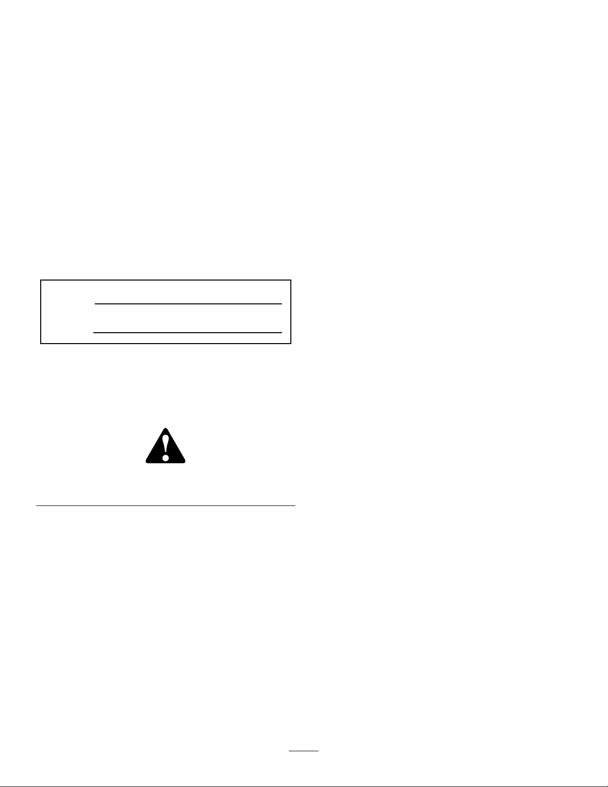
ToroMowerSafety
Thefollowinglistcontainssafetyinformationspecic
toToroproductsorothersafetyinformationthatyou
mustknowthatisnotincludedintheCEN,ISO,or
ANSIstandard.
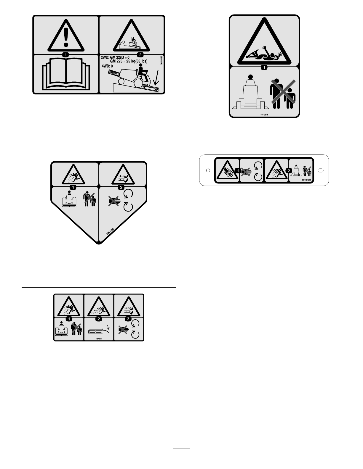
Thisproductiscapableofamputatinghandsand
feetandthrowingobjects.Alwaysfollowallsafety
instructionstoavoidseriousinjuryordeath.
Useofthisproductforpurposesotherthanitsintended
usecouldprovedangeroustouserandbystanders.
•Knowhowtostoptheenginequickly.
•Donotoperatethemachinewhilewearingtennis
shoesorsneakers.
•Wearingsafetyshoesandlongpantsisadvisableand
requiredbysomelocalordinancesandinsurance
regulations.
•Handlefuelcarefully.Wipeupanyspills.
•Checkthesafetyinterlockswitchesdailyforproper
operation.Ifaswitchshouldfail,replacetheswitch
beforeoperatingthemachine.
•Usingthemachinedemandsattention.Toprevent
lossofcontrol:
–Donotdriveclosetosandtraps,ditches,creeks,
embankments,orotherhazards.
–Avoidsuddenstopsandstarts.
–Whennearorcrossingroads,alwaysyieldthe
right-of-way.
–Lowerthecuttingunitwhengoingdownslopes.
•Thegrassdeectormustalwaysbeinstalledandin
thelowestpositiononthesidedischargecutting
unit.Neveroperatethemowerwithoutthedeector
orentiregrasscollector.
•Ifthecuttingunitdischargeareaeverplugs,shutthe
engineoffbeforeremovingtheobstruction.
•Cutgrassslopescarefully.Donotstart,stop,orturn
suddenly.
•Donottouchtheengineormuferwhiletheengine
isrunningorsoonafterithasstoppedbecausethese
areascouldbehotenoughtocauseburns.
MaintenanceandStorage
•Checktheblademountingboltsfrequentlytobe
surethattheyaretightenedtospecication.
•Makesurethatallhydrauliclineconnectorsare
tightandallhydraulichosesandlinesareingood
conditionbeforeapplyingpressuretothesystem.
•Keepyourbodyandhandsawayfrompinhole
leaksornozzlesthatejecthydraulicuidunderhigh
pressure.Usepaperorcardboard,notyourhands,
4