Safety
Hazardcontrolandaccidentpreventionare
dependentupontheawareness,concern,and
propertrainingofthepersonnelinvolvedinthe
operation,transport,maintenance,andstorageof
themachine.Improperuseormaintenanceofthe
machinecanresultininjuryordeath.Toreduce
thepotentialforinjuryordeath,complywiththe
followingsafetyinstructions.
•Read,understand,andfollowallinstructionsinthe
tractionunitandcuttingunitoperatorsmanual’s
beforeoperatingthecuttingunit.
•Neverallowchildrentooperatethetractionunitor
cuttingunits.Donotallowadultstooperatetraction
unitorcuttingunitswithoutproperinstruction.
Onlytrainedoperatorswhohavereadthismanual
shouldoperatethetractionunitorcuttingunits.
•Neveroperatethecuttingunitswhenunderthe
inuenceofdrugsoralcohol.
•Keepallshieldsandsafetydevicesinplace.Ifa
shield,safetydeviceordecalisillegibleordamaged,
repairorreplaceitbeforeoperationiscommenced.
Alsotightenanyloosenuts,bolts,andscrewsto
ensurecuttingunitisinsafeoperatingcondition.
•Alwayswearsubstantialshoes.Donotoperate
cuttingunitswhilewearingsandals,tennisshoes,
sneakersorshorts.Also,donotwearloosetting
clothingwhichcouldgetcaughtinmovingparts.
Alwayswearlongpantsandsubstantialshoes.
Wearingsafetyglasses,safetyshoesandahelmetis
advisableandrequiredbysomelocalordinancesand
insuranceregulations.
•Removealldebrisorotherobjectsthatmightbe
pickedupandthrownbythecuttingunitreelblades.
Keepallbystandersawayfromtheworkingarea.
•Ifthecuttingbladesstrikeasolidobjectortheunit
vibratesabnormally,stopandshuttheengineoff.
Checkcuttingunitfordamagedparts.Repairany
damagebeforerestartingandoperatingthecutting
unit.
•Lowerthecuttingunitstothegroundandremove
keyfromignitionswitchwhenevermachineisleft
unattended.
•Besurecuttingunitsareinsafeoperatingcondition
bykeepingnuts,boltsandscrewstight.
•Removekeyfromignitionswitchtoprevent
accidentalstartingoftheenginewhenservicing,
adjustingorstoringthemachine.
•Performonlythosemaintenanceinstructions
describedinthismanual.Ifmajorrepairsare
everneededorassistanceisdesired,contactan
AuthorizedToroDistributor.
•Toensureoptimumperformanceandsafety,always
purchasegenuineTororeplacementpartsand
accessoriestokeeptheToroallTORO.Neveruse
"will-t"replacementpartsandaccessories
madebyothermanufacturers.Lookforthe
Torologotoassuregenuineness.Usingunapproved
replacementpartsandaccessoriescouldvoidthe
warrantyofTheToroCompany.
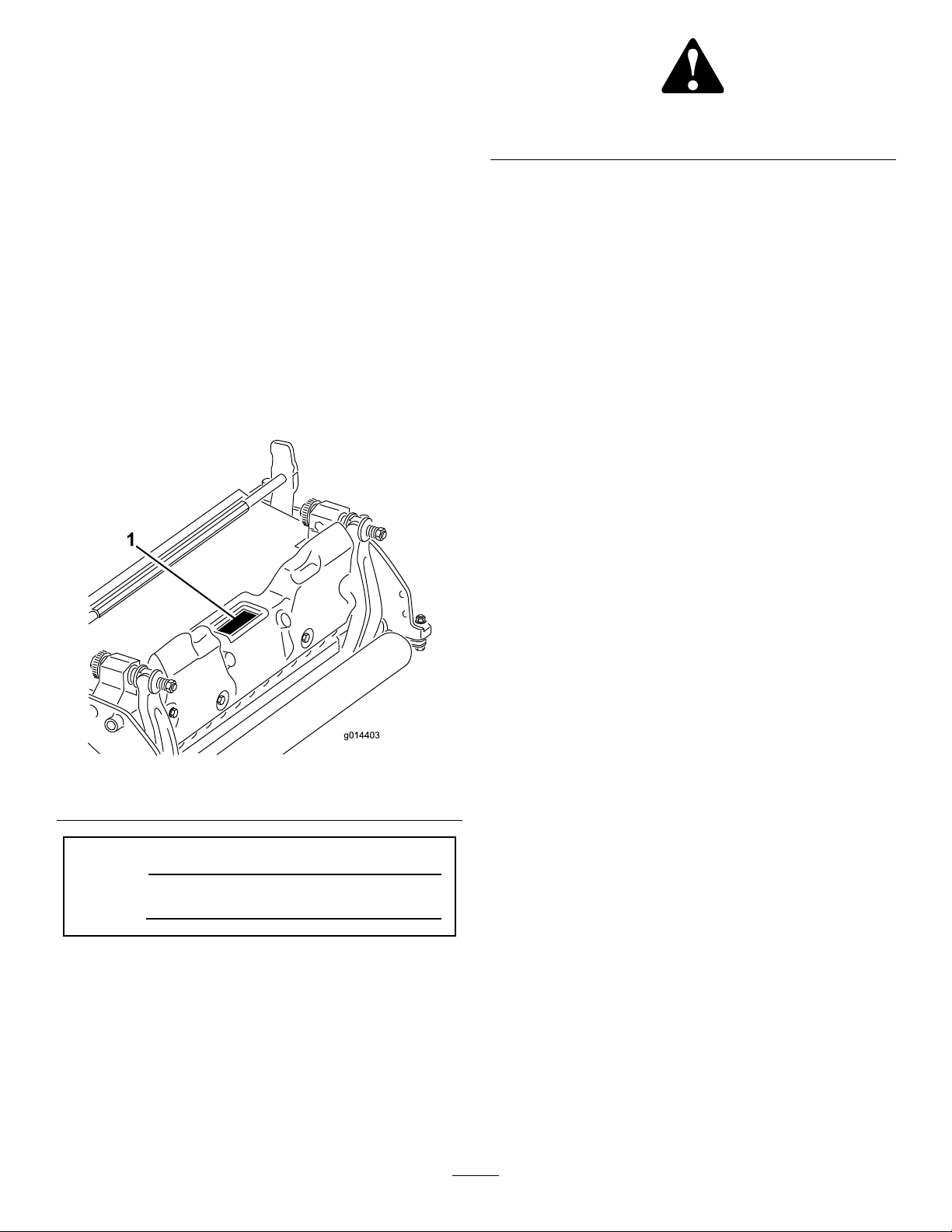
SafetyandInstructionalDecals
Safetydecalsandinstructionsareeasilyvisibletotheoperatorandarelocatednearanyareaof
potentialdanger.Replaceanydecalthatisdamagedorlost.
104–7729
1.Warning—readthe
instructionsbefore
servicingorperforming
maintenance.
2.Cutting/dismemberment
hazard;handorfoot—stop
theengineandwaitfor
movingpartstostop.
3