Toro 31335 User manual

FormNo.3391-342RevA
72inGuardian®Recycler®Mower
Groundsmaster®3280-DTractionUnit
ModelNo.31335—SerialNo.315000001andUp
ModelNo.31336—SerialNo.315000001andUp
Registeratwww.Toro.com.
OriginalInstructions(EN)*3391-342*A

ThisproductcomplieswithallrelevantEuropeandirectives.
Fordetails,pleaseseetheDeclarationofIncorporation(DOI)
atthebackofthispublication.
WARNING
CALIFORNIA
Proposition65Warning
Thisproductcontainsachemicalorchemicals
knowntotheStateofCaliforniatocausecancer,
birthdefects,orreproductiveharm.
Introduction
Thisrotary-bladelawncuttingdeckismountedtoaride-on
machineandisintendedtobeusedbyprofessional,hired
operatorsincommercialapplications.Itisprimarilydesigned
forcuttinggrassonwell-maintainedlawnsinparks,sports
elds,andoncommercialgrounds.Itisnotdesignedfor
cuttingbrush,mowinggrassandothergrowthalongside
highways,orforagriculturaluses.
Readthisinformationcarefullytolearnhowtooperateand
maintainyourproductproperlyandtoavoidinjuryand
productdamage.Youareresponsibleforoperatingthe
productproperlyandsafely.
YoumaycontactTorodirectlyatwww .Toro.comforproduct
andaccessoryinformation,helpndingadealer,ortoregister
yourproduct.
Wheneveryouneedservice,genuineToroparts,oradditional
information,contactanAuthorizedServiceDealerorToro
CustomerServiceandhavethemodelandserialnumbers
ofyourproductready.Themodelandserialnumbersare
stampedintoaplatethatismountedonthemowerhousing.
Writethenumbersinthespaceprovided.
ModelNo.
SerialNo.
Thismanualidentiespotentialhazardsandhassafety
messagesidentiedbythesafetyalertsymbol(Figure1),
whichsignalsahazardthatmaycauseseriousinjuryordeath
ifyoudonotfollowtherecommendedprecautions.
Figure1
1.Safetyalertsymbol
Thismanualuses2wordstohighlightinformation.
Importantcallsattentiontospecialmechanicalinformation
andNoteemphasizesgeneralinformationworthyofspecial
attention.
Contents
Safety...........................................................................3
SafeOperatingPractices...........................................3
ToroMowerSafety..................................................4
SafetyandInstructionalDecals.................................6
Setup............................................................................8
1SecuringtheGrassDeector(Model31336
only)..................................................................9
2InstallingtheLiftArmstotheTraction
Unit...................................................................9
3ConnectingtheLiftArmstotheCutting
Unit..................................................................10
4ConnectingthePTOShafttotheCuttingUnit
GearBox...........................................................10
5GreasingtheMachine...........................................11
ProductOverview.........................................................11
Specications........................................................11
Attachments/Accessories........................................11
Operation....................................................................12
CheckingtheLubricantintheGearBox.....................12
AdjustingtheHeight-of-Cut....................................12
AdjustingtheRollers...............................................13
AdjustingtheSkids.................................................14
AdjustingtheAnti-ScalpRollers...............................14
AdjustingtheFlowBafe(Model31336
only).................................................................14
PositioningtheFlowBafe(Model31336
only).................................................................15
AdjustingtheCuttingUnitPitch...............................16
CorrectingaCuttingUnitMismatch..........................16
UsingtheSideDischarge(Model31336
only).................................................................16
OperatingTips......................................................17
Maintenance.................................................................18
RecommendedMaintenanceSchedule(s)......................18
Lubrication............................................................19
RemovingtheCover...............................................20
SeparatingtheCuttingUnitfromtheTraction
Unit..................................................................20
MountingtheCuttingUnittotheTraction
Unit..................................................................20
ServicingtheBushingsintheCastorArms.................21
ServicingtheCastorWheelsandBearings..................21
CheckingforaBentBlade........................................22
RemovingandInstallingtheBlade(s).........................22
InspectingandSharpeningtheBlade(s)......................23
CheckingandCorrectingMismatchof
Blades...............................................................24
ReplacingtheDriveBelt..........................................24
ReplacingtheGrassDeector..................................25
©2014—TheToro®Company
8111LyndaleAvenueSouth
Bloomington,MN554202
Contactusatwww.Toro.com.
PrintedintheUSA.
AllRightsReserved

Safety
ThismachinehasbeendesignedinaccordancewithENISO
5395:2013andANSIB71.4-2012.
Improperuseormaintenancebytheoperatororownercan
resultininjury.Toreducethepotentialforinjury,complywith
thesesafetyinstructionsandalwayspayattentiontothesafety
alertsymbol,whichmeans—personalsafetyinstruction—
Failuretocomplywiththeinstructionmayresultinpersonal
injuryordeath.
SafeOperatingPractices
Training
•Readtheoperator'smanualandothertrainingmaterial
carefully.Befamiliarwiththecontrols,safetysigns,and
theproperuseoftheequipment.Iftheoperatoror
mechaniccannotreadthelanguageofthismanual,itis
theowner'sresponsibilitytoexplainthismaterialtothem.
•Becomefamiliarwiththesafeoperationoftheequipment,
operatorcontrols,andsafetysigns.
•Alloperatorsandmechanicsshouldbetrained.The
ownerisresponsiblefortrainingtheusers
•Neverletchildrenoruntrainedpeopleoperateorservice
theequipment.Localregulationsmayrestricttheageof
theoperator.
•Theowner/usercanpreventandisresponsiblefor
accidentsorinjuriesoccurringtohimselforherself,other
people,orproperty.
Preparation
•Evaluatetheterraintodeterminewhataccessoriesand
attachmentsareneededtoproperlyandsafelyperform
thejob.Onlyuseaccessoriesandattachmentsapproved
bythemanufacturer.
•Wearappropriateclothingincludinghardhat,safety
glassesandearprotection.Longhair,looseclothingor
jewelrymaygettangledinmovingparts.
•Inspecttheareawheretheequipmentistobeusedand
removeallobjectssuchasrocks,toysandwirewhichcan
bethrownbythemachine.
•Checkthatoperator'spresencecontrols,safetyswitches
andshieldsareattachedandfunctioningproperly.Donot
operateunlesstheyarefunctioningproperly.
SafeHandlingofFuels
•Toavoidpersonalinjuryorpropertydamage,use
extremecareinhandlinggasoline.Gasolineisextremely
ammableandthevaporsareexplosive.
•Extinguishallcigarettes,cigars,pipes,andothersources
ofignition.
•Useonlyanapprovedfuelcontainer.
•Neverremovefuelcaporaddfuelwiththeengine
running.
•Allowenginetocoolbeforerefueling.
•Neverrefuelthemachineindoors.
•Neverstorethemachineorfuelcontainerwherethereis
anopename,spark,orpilotlightsuchasonawater
heateroronotherappliances.
•Neverllcontainersinsideavehicleoronatruckor
trailerbedwithaplasticliner.Alwaysplacecontainerson
thegroundawayfromyourvehiclebeforelling.
•Removeequipmentfromthetruckortrailerandrefuelit
ontheground.Ifthisisnotpossible,thenrefuelsuch
equipmentwithaportablecontainer,ratherthanfroma
fueldispensernozzle.
•Keepthenozzleincontactwiththerimofthefueltank
orcontaineropeningatalltimesuntilfuelingiscomplete.
Donotuseanozzlelockopendevice.
•Iffuelisspilledonclothing,changeclothingimmediately.
•Neveroverllfueltank.Replacefuelcapandtighten
securely.
Operation
•Neverrunanengineinanenclosedarea.
•Onlyoperateingoodlight,keepingawayfromholesand
hiddenhazards.
•Besurealldrivesareinneutralandparkingbrakeis
engagedbeforestartingengine.Onlystartenginefrom
theoperator'sposition.Alwaysusetheseatbeltswhen
theROPSisintheraisedposition.Donotusetheseat
beltswhentheROPSisintheloweredposition.
•Slowdownanduseextracareonhillsides.Besureto
travelintherecommendeddirectiononhillsides.Turf
conditionscanaffectthemachine'sstability.Usecaution
whileoperatingneardrop-offs.
•Slowdownandusecautionwhenmakingturnsandwhen
changingdirectionsonslopes.
•Neverraisedeckwiththebladesrunning.
•Neveroperatewithguardsnotsecurelyinplace.Be
sureallinterlocksareattached,adjustedproperly,and
functioningproperly.
•Donotchangetheenginegovernorsettingoroverspeed
theengine.
•Stoponlevelground,lowerthecuttingunits,disengage
drives,engageparkingbrake(ifprovided),shutoffengine
beforeleavingtheoperator'spositionforanyreason.
•Stopequipmentandinspectthebladesafterstriking
objectsorifanabnormalvibrationoccurs.Make
necessaryrepairsbeforeresumingoperations.
•Keephandsandfeetawayfromthecuttingunits.
•Lookbehindanddownbeforebackinguptobesureof
aclearpath.
3

•Nevercarrypassengersandkeeppetsandbystanders
away.
•Slowdownandusecautionwhenmakingturnsand
crossingroadsandsidewalks.Stopbladesifnotmowing.
•Donotoperatethemowerundertheinuenceofalcohol
ordrugs.
•Lightningcancausesevereinjuryordeath.Iflightning
isseenorthunderisheardinthearea,donotoperate
themachine;seekshelter.
•Usecarewhenloadingorunloadingthemachineintoa
trailerortruck.
•Usecarewhenapproachingblindcorners,shrubs,trees,
orotherobjectsthatmayobscurevision.
•Theoperatorshallturnonashingwarninglights,if
provided,whenevertravelingonapublicroad,except
wheresuchuseisprohibitedbylaw .
MaintenanceandStorage
•Disengagedrives,lowerthecuttingunits,movetraction
pedaltoNeutral,setparkingbrake,stopengineand
removekey.Waitforallmovementtostopbefore
adjusting,cleaningorrepairing.
•Cleangrassanddebrisfromcuttingunits,drives,mufer.
Letenginecoolbeforestoringanddonotstorenear
ames,andenginetohelppreventres.Cleanupoilor
fuelspillage.
•Letenginecoolbeforestoringanddonotstorenear
ame.
•Shutofffuelwhilestoringortransporting.Donotstore
fuelnearamesordrainindoors.
•Parkmachineonlevelground.Neverallowuntrained
personneltoservicemachine.
•Usejackstandstosupportcomponentswhenrequired.
•Carefullyreleasepressurefromcomponentswithstored
energy.
•Disconnectbatterybeforemakinganyrepairs.Disconnect
thenegativeterminalrstandthepositivelast.Reconnect
positiverstandnegativelast.
•Usecarewhencheckingblades.Wrapthebladesor
weargloves,andusecautionwhenservicingthem.Only
replaceblades.Neverstraightenorweldthem.
•Keephandsandfeetawayfrommovingparts.Ifpossible,
donotmakeadjustmentswiththeenginerunning.
•Chargebatteriesinanopenwellventilatedarea,away
fromsparkandames.Unplugchargerbeforeconnecting
ordisconnectingfrombattery.Wearprotectiveclothing
anduseinsulatedtools.
•Keepallpartsingoodworkingconditionandallhardware
tightened.Replaceallwornordamageddecals.
Hauling
•Usecarewhenloadingorunloadingthemachineintoa
trailerortruck.
•Usefullwidthrampsforloadingmachineintotraileror
truck.
•Tiethemachinedownsecurelyusingstraps,chains,cable,
orropes.Bothfrontandrearstrapsshouldbedirected
downandoutwardfromthemachine.Makesurethe
enginehoodissecurelystrappeddown.
ToroMowerSafety
ThefollowinglistcontainssafetyinformationspecictoToro
productsorothersafetyinformationthatyoumustknowthat
isnotincludedintheCEN,ISO,orANSIstandard.
Thisproductiscapableofamputatinghandsandfeetand
throwingobjects.Alwaysfollowallsafetyinstructionsto
avoidseriousinjuryordeath.
Useofthisproductforpurposesotherthanitsintendeduse
couldprovedangeroustouserandbystanders.
•Knowhowtostoptheenginequickly.
•Donotoperatethemachinewhilewearingtennisshoes
orsneakers.
•Wearingsafetyshoesandlongpantsisadvisableand
requiredbysomelocalordinancesandinsurance
regulations.
•Handlefuelcarefully.Wipeupanyspills.
•Checkthesafetyinterlockswitchesdailyforproper
operation.Ifaswitchshouldfail,replacetheswitch
beforeoperatingthemachine.
•Usingthemachinedemandsattention.Topreventloss
ofcontrol:
–Donotdriveclosetosandtraps,ditches,creeks,
embankments,orotherhazards.
–Avoidsuddenstopsandstarts.
–Whennearorcrossingroads,alwaysyieldthe
right-of-way.
–Lowerthecuttingunitwhengoingdownslopes.
•Thegrassdeectormustalwaysbeinstalledandinthe
lowestpositiononthesidedischargecuttingunit.Never
operatethemowerwithoutthedeectororentiregrass
collector.
•Ifthecuttingunitdischargeareaeverplugs,shutthe
engineoffbeforeremovingtheobstruction.
•Cutgrassslopescarefully.Donotstart,stop,orturn
suddenly.
•Donottouchtheengineormuferwhiletheengineis
runningorsoonafterithasstoppedbecausetheseareas
couldbehotenoughtocauseburns.
MaintenanceandStorage
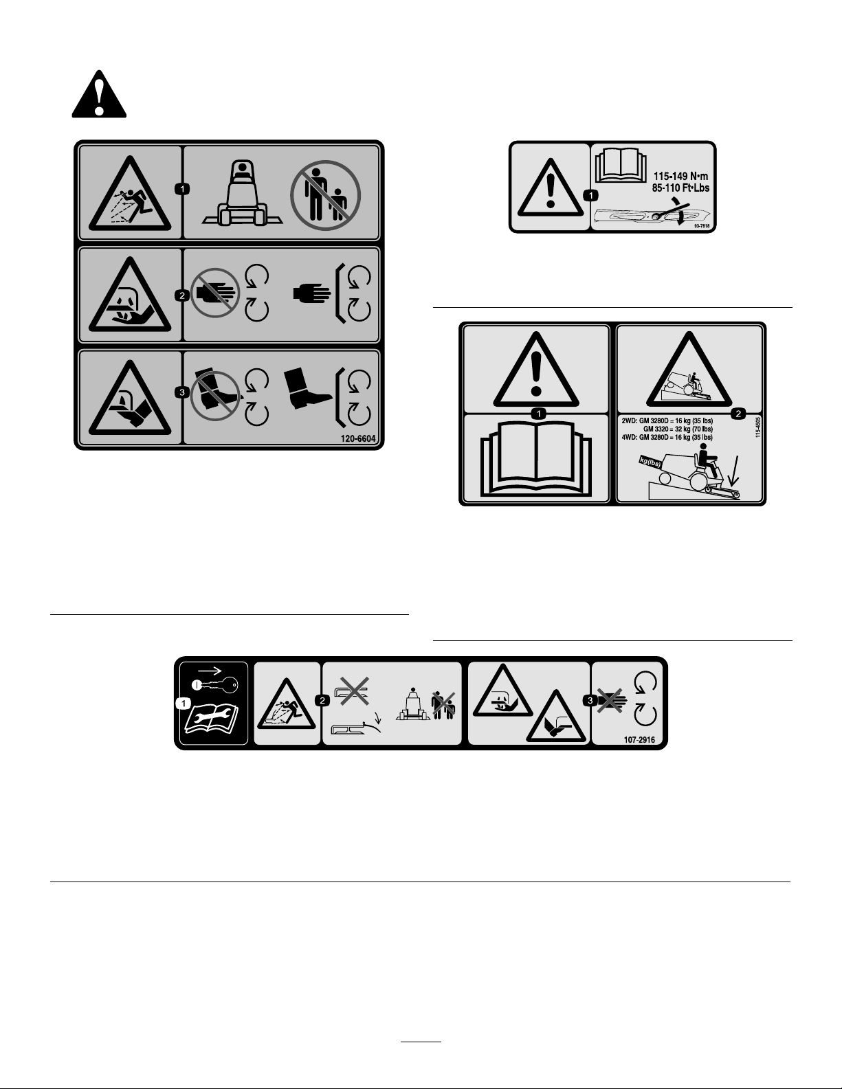
•Checktheblademountingboltsfrequentlytobesurethat
theyaretightenedtospecication.
4

•Makesurethatallhydrauliclineconnectorsaretightand
allhydraulichosesandlinesareingoodconditionbefore
applyingpressuretothesystem.
•Keepyourbodyandhandsawayfrompinholeleaksor
nozzlesthatejecthydraulicuidunderhighpressure.
Usepaperorcardboard,notyourhands,tosearchfor
leaks.Hydraulicuidescapingunderpressurecanhave
sufcientforcetopenetratetheskinandcauseserious
injury.
•Beforedisconnectingorperforminganyworkonthe
hydraulicsystem,allpressureinthesystemmustbe
relievedbystoppingtheengineandloweringthecutting
unitstotheground.
•Iftheenginemustberunningtoperformamaintenance
adjustment,keephands,feet,clothing,andanypartsof
thebodyawayfromthecuttingunits,attachments,and
anymovingparts.Keepeveryoneaway.
•Donotoverspeedtheenginebychanginggovernor
settings.Toensuresafetyandaccuracy,havean
AuthorizedToroDistributorcheckthemaximumengine
speedwithatachometer.
•Theenginemustbeshutoffbeforecheckingtheoilor
addingoiltothecrankcase.
•Makesurethatthemowerfueltankisemptyifthe
machineistobestoredinexcessof30days.Donotstore
themowernearanyopenameorwheregasolinefumes
maybeignitedbyaspark.
•Performonlythosemaintenanceinstructionsdescribed
inthismanual.Ifmajorrepairsareeverneededor
ifassistanceisdesired,contactanAuthorizedToro
Distributor.
•Tomakesureofoptimumperformanceandcontinued
safetycerticationofthemachine,useonlygenuineToro
replacementpartsandaccessories.Replacementparts
andaccessoriesmadebyothermanufacturerscouldbe
dangerous,andsuchusecouldvoidtheproductwarranty.
5

SafetyandInstructionalDecals
Safetydecalsandinstructionsareeasilyvisibletotheoperatorandarelocatednearanyareaofpotential
danger.Replaceanydecalthatisdamagedorlost.
120-6604
1.Thrownobjecthazard—keepbystandersawayfromthe
machine.
2.Cutting/dismembermenthazardofhand,mower
blade—stayawayfrommovingparts,keepallguardsand
shieldsinplace.
3.Cutting/dismembermenthazardoffoot,mowerblade—stay
awayfrommovingparts,keepallguardsandshieldsin
place.
93-7818
1.Warning—readtheOperator'sManualforinstructionson
torquingthebladebolt/nutto115-149N-m(85-110ft-lb).
115-4505
1.Warning—readtheOperator'sManual.
2.Tippinghazard—lowerthecuttingunitwhendrivingdown
slopes.For2wheeldriveunits,adda16kg(35lb)rear
weighttoGM3280Dunitsanda32kg(70lb)rearweightto
GM3320units.For4wheeldrive3280Dunits,adda16
kg(35lb)rearweight.
107-2916
Model31336only
1.Removetheignitionkeyandreadthe
Operator'sManualbeforeservicingor
performingmaintenance.
2.Thrownobjecthazard—donotoperate
themowerwiththedeectorupor
removed,keepthedeectorinplace;
keepbystandersasafedistancefrom
themachine.
3.Cutting/dismembermenthazardof
handorfoot,mowerblade—stayaway
frommovingparts.
6

93-6697
1.ReadtheOperator's
Manual.
2.AddSAE80w-90(API
GL-5)oilevery50hours.
117–4979
1.Entanglementhazard,belt—stayawayfrommovingparts,
keepallguardsandshieldsinplace.
107-2908
Model31336only
1.Thrownobjecthazard—keepbystandersasafedistance
fromthemachine.
2.Thrownobjecthazard—donotoperatethemowerwiththe
deectoruporremoved,keepthedeectorinplace.
3.Cutting/dismembermenthazardofhandorfoot,mower
blade—stayawayfrommovingparts.
108-1988
1.Beltrouting
100-5622
1.Heightofcutadjustment
107-1622
Model31336only
7

Setup
LooseParts
Usethechartbelowtoverifythatallpartshavebeenshipped.
ProcedureDescriptionQty.Use
1Nopartsrequired–Securethegrassdeector
Liftarm,right1
2Liftarm,left1Installtheliftarmstothetractionunit
3Nopartsrequired–Connecttheliftarmstothecuttingunit
4Nopartsrequired–ConnectthePTOshafttothecutting
unitgearbox.
5Nopartsrequired–Greasethemachine.
MediaandAdditionalParts
DescriptionQty.Use
Operator'sManual1Reviewthematerialandsaveinanappropriateplace
PartsCatalog1Usetoreferencepartnumbers
DeclarationofConformity1
WARNING
Ifyouleavethekeyintheignitionswitch,someone
couldaccidentallystarttheengineandseriously
injureyouorotherbystanders.
Removethekeyfromtheignitionswitchbeforeyou
doanymaintenance.
DANGER
IftheengineisstartedandthePTOshaftisallowed
torotate,seriousinjurycouldresult.
DonotstarttheengineandengagethePTOswitch
whenthePTOshaftisnotconnectedtothegear
boxonthecuttingunit.
Note:Determinetheleftandrightsidesofthemachine
fromthenormaloperatingposition.
8

Important:Ifthe72inchSideDischargeCuttingUnit,
model31336,isbeingmountedtoamodel30307,30308,
30309,30343,30344or30345tractionunitwithaserial
numberpriorto311000301,theCuttingUnitAlignment
Kit,partnumber120–6599mustbeinstalledtothe
cuttingunitpriortobeingmountedtotractionunit.
1
SecuringtheGrassDeector
(Model31336only)
NoPartsRequired
Procedure
WARNING
Anuncovereddischargeopeningcouldallowthe
lawnmowertothrowobjectsintheoperator'sor
bystander'sdirectionandresultinseriousinjury.
Also,contactwiththebladecouldoccur.
•Neveroperatethelawnmowerunlessyouinstall
acoverplate,amulchplate,oragrasschuteand
catcher.
•Makesurethegrassdeectorisinthedown
position.
1.Removethecabletiesecuringthegrassdeectortothe
topofthedeckandlowerthedeector.
2.PlacethelefthandJhookendofthespringaround
thedeckedge
3.PlacetherighthandJhookendofthespringaround
thegrassdeector(Figure2).
Important:Thegrassdeectormustbeableto
lowerdownintoposition.Liftthedeectorupto
testthatitlowersintothefulldownposition.
G018264
12
3
4
5
Figure2
1.GrassDeector4.Lefthandhookendof
spring,placebehinddeck
edge
2.Spring5.Springinstalled
3.Righthandhookend
ofspring,placearound
deector
2
InstallingtheLiftArmstothe
TractionUnit
Partsneededforthisprocedure:
1Liftarm,right
1Liftarm,left
Procedure
1.Ononesideofthetractionunit,loosen(donot
remove)thewheelnutssecuringthewheelandtire
assemblytothefrontwheelstuds.
2.Jackupthemachineuntilthefrontwheelisoffofthe
oor.Usejackstandsorblockthemachinetoprevent
itfromaccidentallyfalling.
3.Removethewheelnutsandslidethewheelandtire
assemblyoffofthestuds.
4.Removetheliftarmsfromthepallet.
5.Removethepivotpinandcotterpinfromeachliftarm.
6.Mountaliftarmtothepivotbracketwithapivotpin
andacotterpin(Figure3).Mounttheliftarmwiththe
bendpositionedoutward.
7.Hookthebrakereturnspringtothetabonthelift
arm(Figure3).
9

Figure3
1.Pivotpin4.Brakereturnspring
2.Liftarm5.Tab
3.Pivotbracket
8.Installthewheelandtireassembly.Torquethewheel
nutsto102-108N-m(75-80ft-lb).
9.Repeattheprocedureontheoppositesideofthe
machine.
3
ConnectingtheLiftArmsto
theCuttingUnit
NoPartsRequired
Procedure
1.Removethe2thrustwashers,clevispinandhairpin
cotterfromeachcastorarmbracketonthecutting
unit(Figure4).
2.Movethecuttingunitintopositioninfrontofthe
tractionunit.
3.PresstheliftswitchforwardtotheFloatposition.Push
aliftarmdownuntiltheholesintheliftarmlineup
withtheholesinthecastorarmbracket(Figure4).
g018216
1
2
3
4
5
Figure4
1.Castorarmbracket4.Liftarm
2.Hairpincotter5.Thrustwasher
3.Clevispin
4.Securetheliftarmtothecastorarmwiththe2thrust
washers,clevispinandhairpincotter.Positionthe
thrustwashersbetweentheliftarmandthecastorarm
bracket(Figure4).Insertendofcotterpinintotheslot
inthecastorarmtabtoretaincotterpin.
5.Repeattheprocedureontheoppositeliftarm.
6.Startthetractionunitandraisethecuttingunit.
4
ConnectingthePTOShaftto
theCuttingUnitGearBox
NoPartsRequired
Procedure
1.SlidethemalePTOshaftintothefemalePTOshaft.
Alignthemountingholesinthegearcaseinputshaft
withtheholesinthePTOshaftandslidethemtogether.
10

Figure5
1.PTOshaft3.Gearcase
2.Boltsandlocknuts4.Rollpin
2.Securethemwitharollpin.
3.Tightentheboltsandnuts.
5
GreasingtheMachine
NoPartsRequired
Procedure
Beforeoperatingthemachine,itmustbegreasedtoensure
properlubricatingcharacteristics;refertoGreasingthe
BearingsandBushings.Failuretoproperlygreasethemachine
willresultinprematurefailureofcriticalparts.
ProductOverview
Specications
Note:Specicationsanddesignaresubjecttochange
withoutnotice.
Width
ofCut
1.829m(72inches)
Height
ofCut
Adjustablefrom25to127mm(1to5inches)in13
mm(1/2inch)increments
Net
Weight
Model31335–251kg(553lb)
Model31336–292kg(643lb)
Attachments/Accessories
AselectionofToroapprovedattachmentsandaccessoriesis
availableforusewiththemachinetoenhanceandexpand
itscapabilities.ContactyourAuthorizedServiceDealeror
Distributororgotowww .Toro.comforalistofallapproved
attachmentsandaccessories.
11

Operation
Note:Determinetheleftandrightsidesofthemachine
fromthenormaloperatingposition.
CAUTION
Ifyouleavethekeyintheignitionswitch,someone
couldaccidentlystarttheengineandseriously
injureyouorotherbystanders.
Removethekeyfromtheignitionbeforeyoudoany
maintenance.
CheckingtheLubricantinthe
GearBox
ServiceInterval:Every50hours
ThegearboxindesignedtooperateonSAE80–90wt.gear
lube.Althoughthegearboxisshippedwithlubricantfrom
thefactory,checkthelevelbeforeoperatingthecuttingunit.
Thegearboxcapacityis283ml(12oz.).
1.Positionthemachineandcuttingunitonalevelsurface.
2.Removethedipstick/llplugfromthetopofthegear
box(Figure6)andmakesurethatthelubricantis
betweenthemarksonthedipstick.Ifthelubricant
levelislow ,addenoughlubricantuntilthelevelis
betweenthemarks.
Figure6
1.Dipstick/llplug
AdjustingtheHeight-of-Cut
Theheight-of-cutisadjustablefrom25to127mm(1to
5inches)in13mm(1/2inch)increments.Toadjustthe
height-of-cut,positionthecastorwheelaxlesintheupperor
lowerholesofthecastorforksandaddorremoveanequal
numberofspacersfromthecastorforks.
1.Starttheengineandraisethecuttingunitofftheoor
sothattheheight-of-cutcanbechanged.Stopthe
engineandremovethekeyafterthecuttingunitis
raised.
2.Positionthecastorwheelaxlesinthesameholesinall
castorforks.RefertoFigure7,Figure8andFigure9
todeterminethecorrectholesforthesetting.
Figure7
1.Tensioningcap4.Axlemountingholes
2.Spacers5.CastorWheel
3.Shims
Figure8
Note:Whenoperatingin64mm(2–1/2inch)height
ofcutorhigher,theaxleboltmustbeinstalledinthe
lowercastorforkholetopreventgrassbuildupbetween
thewheelandthefork.Whenoperatinginheight
ofcutslowerthan64mm(2–1/2inches)andgrass
buildupisdetected,reversethemachinesdirectionto
pullanyclippingsawayfromthewheel/forkarea.
12

FrontCastorWheels
1.Removethetensioningcapfromthespindleshaft
(Figure7)andslidethespindleoutofthecastorarm.
Putthe2shims(1/8inch)ontothespindleshaftas
theywereoriginallyinstalled.Theseshimsarerequired
toachievealevelacrosstheentirewidthofthecutting
units.Slidetheappropriatenumberof1/2inchspacers
ontothespindleshafttogetthedesiredheight-of-cut;
thenslidethewasherontotheshaft.
RefertoFigure8todeterminethecombinationsof
spacersforthesetting.
2.Pushthecastorspindlethroughthecastorarm.Install
theshims(astheywereoriginallyinstalled)andthe
remainingspacersontothespindleshaft.Installthe
tensioningcaptosecuretheassembly.
Note:Whenusing25mm(1inch),38mm(1-1/2
inch),oroccasionally51mm(2inch)height–of–cut,
movetheskidsandrollertothehighestholes.
RearCastorWheels
1.Removethetensioningcapfromthespindleshaft
(Figure9).
5
G018263
Figure9
1.Tensioningcap4.CastorWheel
2.Shims5.Axlemountingholes
3.“C”Shapedspacers
Note:Therearcastorforkassemblydoesnotneed
toberemovedfromthecastorarmtochangethe
height-of-cut.
2.Removeoradd”C”shapedspacersatthenarrow
portionofthespindleshaft,belowthecastorarm,to
getthedesiredheight-of-cut.Makesurethattheshims,
notthespacers,contactthetopandbottomofthe
castorarm.
3.Installthetensioningcaptosecuretheassembly.
4.Ensurethatallfourcastorwheelsaresetatthesame
height-of-cut.
Note:Whenusing25mm(1inch),38mm(1-1/2inch),or
occasionally51mm(2inch)height–of–cut,movetheskids
androllertothehighestholes.
AdjustingtheRollers
Note:Ifthecuttingunitistobeusedinthe25or38mm(1
or1-1/2inch)height-of-cutsetting,thecuttingunitrollers
mustberepositionedinthetopbracketholes.
Toadjustthefrontrollers(Figure10).
1.Removethescrewandnutsecuringtherollershaftto
thedeckbracket.
Figure10
1.Roller2.Rollershaft
2.Slidetheshaftoutofthelowerbracketholes,alignthe
rollerwiththetopholes,andinstalltheshaft.
3.Installthescrewandnuttosecuretheassemblies.
Toadjusttherear(internal)rollers(Figure11)
Figure11
1.Internalrollers
13

AdjustingtheSkids
Theskidsshouldbemountedinthelowerpositionwhen
operatinginheightofcutsgreaterthan64mm(2–1/2inches)
andinthehigherpositionwhenoperatinginheightofcuts
lowerthan64mm(2–1/2inches).
Adjusttheskidsbyremovingtheangeboltandnuts,
positioningthemasdesired,andinstallingthefasteners
(Figure12).
Figure12
1.Skid
AdjustingtheAnti-Scalp
Rollers
Wheneveryouchangetheheight-of-cut,itisrecommended
toadjusttheheightoftheanti-scalprollers.
1.Afteradjustingtheheight-of-cut,adjusttherollersby
removingtheangenut,bushing,spacer,andbolt
(Figure13).
Figure13
1.Anti-scalproller4.Flangenut
2.Spacer5.Bolt
3.Bushing
2.Selectaholesotheanti-scalprollerispositionedtothe
nearestcorrespondingheight-of-cutdesired.
3.Installtheangenut,bushing,spacer,andbolt.Torque
to54-61N-m(40-45ft-lb)(Figure13).
AdjustingtheFlowBafe
(Model31336only)
Themowerdischargeowcanbeadjustedfordifferenttypes
ofmowingconditions.Positionthecamlocksandbafeto
givethebestqualityofcut.
1.Toadjustthecamlocks,swingtheleveruptoloosen
thecamlock(Figure14).
2.Adjustthebafeandcamlocksintheslotstothe
desireddischargeow.
14

3.Swingtheleverbackovertotightenthebafeandcam
locks(Figure14).
4.Ifthecamlocksdonotlockthebafeintoplaceorit
istootight,loosentheleverandthenrotatethecam
lock.Adjustthecamlockuntilthedesiredlocking
pressureisachieved.
G008961
12
34
Figure14
1.Unlocklever3.Positionthebafe
2.Rotatethecamlockto
increaseordecrease
lockingpressure
4.Locklever
PositioningtheFlowBafe
(Model31336only)
Thefollowingguresareonlyrecommendationsforuse.
Adjustmentswillvarybygrasstype,moisturecontent,and
heightofgrass.
Note:Iftheenginepowerdrawsdownandthemower
groundspeedisthesame,openupthebafe.
PositionA
Thisisthefullrearposition.Thesuggesteduseforthis
positionisafollows.
•Useforshort,lightgrassmowingconditions.
•Useindryconditions.
•Forsmallergrassclippings.
•Propelsgrassclippingsfartherawayfromthemower.
Figure15
PositionB
Usethispositionwhenbagging.Alwaysalignitwiththe
bloweropening.
Figure16
PositionC
Thisisthefullopenposition.Thesuggesteduseforthis
positionisasfollows.
•Useintall,densegrassmowingconditions.
•Useinwetconditions.
•Lowerstheenginepowerconsumption.
•Allowsincreasedgroundspeedinheavyconditions.
Figure17
15

AdjustingtheCuttingUnit
Pitch
Cuttingunitpitchisthedifferenceinheight-of-cutfromthe
frontofthebladeplanetothebackofthebladeplane.Toro
recommendsabladepitchof8mm(5/16inch).Thatisthe
backofthebladeplaneis8mm(5/16inch)higherthanthe
front.
1.Positionthemachineonalevelsurfaceontheshop
oor.
2.Setthecuttingunittothedesiredheight-of-cut.
3.Rotate1bladesothatitpointsstraightforward.
4.Usingashortruler,measurefromtheoortothefront
tipoftheblade.Rotatethebladetiptotherearand
measurefromtheoortothetipoftheblade.
5.Subtractthefrontdimensionfromthereardimension
tocalculatethebladepitch.
6.Adjusttheshims,onthefrontorrearcastorarms,to
attaintherequiredcuttingunitpitch(Figure18).
5
G018263
Figure18
1.Tensioningcap4.CastorWheel
2.Shims5.Axlemountingholes
3.“C”Shapedspacers
CorrectingaCuttingUnit
Mismatch
Duetodifferencesingrassconditionsandthecounterbalance
settingofthetractionunit,itisadvisedthatgrassbecutand
appearancecheckedbeforeformalcuttingisstarted.
1.Setthecuttingunittothedesiredheightofcut;referto
AdjustingtheHeight-of-Cut(page12).
2.Checkandadjustfrontandreartractortirepressure
to138kPa(20psi).
3.Checkandadjustallcastortirepressuresto345kPa
(50psi).
4.Checkforbentblades;refertoCheckingforaBent
Blade.
5.Cutgrassinatestareatodetermineifallcuttingunits
arecuttingatthesameheight.
6.Ifcuttingunitadjustmentsarestillneeded,ndaat
surfaceusinga2m(6foot)orlongerstraightedge.
7.Toeasemeasuringbladeplane,raisetheheightof
cuttothehighestposition;refertoAdjustingthe
Height-of-Cut(page12).
8.Lowerthecuttingunitontotheatsurface.Remove
thecoversfromthetopofthecuttingunits.
9.Rotatethebladeoneachspindleuntiltheendsface
forwardandbackward.
10.Measurefromtheoortothefronttipofthecutting
edge.
11.Adjusttheshimsonthecastorfork(s)tomatch
theheightofcuttodecal;refertoAdjustingthe
Height-of-Cut(page12).
UsingtheSideDischarge
(Model31336only)
Themowerhasahingedgrassdeectorthatdisperses
clippingstothesideanddowntowardtheturf.
DANGER
Withoutagrassdeector,dischargecover,or
completegrasscatcherassemblymountedin
place,youandothersareexposedtobladecontact
andthrowndebris.Contactwithrotatingmower
blade(s)andthrowndebriswillcauseinjuryor
death.
•Neverremovethegrassdeectorfromthemower
becausethegrassdeectorroutesmaterialdown
towardtheturf.Ifthegrassdeectorisever
damaged,replaceitimmediately.
•Neverputyourhandsorfeetunderthemower.
•Nevertrytoclearthedischargeareaormower
bladesunlessyoumovethepowertakeoff(blade
controlswitch(PTO)totheoffposition,rotate
theignitionkeytooffandremovethekey.
•Makesurethegrassdeectorisinthedown
position.
16

OperatingTips
MowingOnlyWhenGrassisDry
Moweitherinthelatemorningtoavoidthedew,whichcauses
grassclumping,orinlateafternoontoavoidthedamage
thatcanbecausedbydirectsunlightonthesensitive,freshly
mowedgrass.
SelectingtheProperHeight-of-Cut
Setting
Removeapproximately25mm(1inch)ornomorethan1/3
ofthegrassbladewhencutting.Inexceptionallylushand
densegrass,youmayhavetoraisetheheight-of-cuttothe
nextsetting.
MowingattheProperIntervals
Undermostnormalconditionsyouwillneedtomow
approximatelyevery4–5days.Butremember,grassgrowsat
differentratesatdifferenttimes.Thismeansthatinorderto
maintainthesameheight-of-cut,whichisagoodpractice,
youwillneedtocutmorefrequentlyinearlyspring;asthe
grassgrowthrateslowsinmidsummer,cutonlyevery8–10
days.Ifyouareunabletomowforanextendedperioddue
toweatherconditionsorotherreasons,mowrstwiththe
height-of-cutatahighlevel;thenmowagain2–3dayslater
withalowerheightsetting.
MowingwithSharpBladesOnly
Asharpbladecutscleanlyandwithouttearingorshredding
thegrassbladeslikeadullblade.Tearingandshredding
causesthegrasstoturnbrownattheedgeswhichimpairs
growthandincreasessusceptibilitytodiseases.
CleaningtheUndersideoftheMachine
Toensureoptimumperformance,cleantheundersideofthe
mowerhousingaftereachuse.Ifresidueisallowedtobuild
upinthemowerhousing,cuttingperformancewilldecrease.
SettingtheCuttingUnitPitch
Werecommendabladepitchof8mm(5/16inch).A
pitchlargerthan8mm(5/16inch)willresultinlesspower
required,largerclippings,andapoorerqualityofcut.Apitch
lessthan8mm(5/16inch)willresultinmorepowerrequired,
smallerclippingsandabetterqualityofcut.
17

Maintenance
RecommendedMaintenanceSchedule(s)
MaintenanceService
IntervalMaintenanceProcedure
Aftertherst2hours•Tightenthecastorwheelnuts.
Aftertherst10hours•Tightenthecastorwheelnuts.
•T orquethebladebolts.
Beforeeachuseordaily
•Lubricatethecastorarmbushings.
•Lubricatethecastorwheelbearings.
•Checktheblades.
Every50hours
•Checkthegearboxlubricant
•Lubricatethegreasettings.
•Tightenthecastorwheelnuts.
•T orquethebladebolts.
•Checkthebladedrivebeltadjustment.
•Cleanunderthecuttingunitbeltcovers.
Every400hours•Changethegearboxlubricant
CAUTION
Ifyouleavethekeyintheignitionswitch,someonecouldaccidentallystarttheengineandseriously
injureyouorotherbystanders.
Removethekeyfromtheignitionswitchbeforeyoudoanymaintenance.
18

Lubrication
ServiceInterval:Every50hours
Themachinehasgreasettingsthatmustbelubricated
regularlywithNo.2General-purposeLithium-baseGrease.
Ifthemachineisoperatedundernormalconditions,lubricate
allbearingsandbushingsafterevery50hoursofoperationor
immediatelyaftereverywashing.
1.Lubricatethefollowingareas:
•Castorforkshaftbushings(4)(Figure19).
Figure19
•Spindleshaftbearings(3)(locatedunderthepulley)
(Figure20)
Figure20
•Idlerarmshaftbearings(Figure20)
•Liftarmpivots,front(2)(Figure21)
Figure21
•Liftarmpivots,rear(2)(Figure22)
Figure22
2.Positionthemachineandcuttingunitonalevelsurface
andlowerthecuttingunit.Removethedipstick/ll
plugfromthetopofthegearbox(Figure23)andmake
surethatthelubricantisbetweenthemarksonthe
dipstick.Ifthelubricantlevelislow,addSAE80-90
wt.gearlubeuntilthelevelisbetweenthemarks.The
gearboxcapacityis283ml(12ounces).
Figure23
1.Dipstick/llplug
19

RemovingtheCover
Important:Thefastenersonthecoversofthismachine
aredesignedtoremainonthecoverafterremoval.
Loosenallofthefastenersoneachcoverafewturnsso
thatthecoverisloosebutstillattached,thengoback
andloosenthemuntilthecovercomesfree.Thiswill
preventyoufromaccidentallystrippingtheboltsfree
oftheretainers.
SeparatingtheCuttingUnit
fromtheTractionUnit
1.Positionthemachineonlevelsurface,lowerthecutting
unittotheoor,movetheliftlevertotheFloat
position,shuttheengineoff,andengagetheparking
brake.
2.Removethehairpincottersandclevispinssecuring
theliftarmstothecastorarmbrackets(Figure24).
Figure24
1.Liftarm3.Hairpincotter
2.Clevispin4.Castorarmbracket
3.Rollthecuttingunitawayfromthetractionunit,
separatingthemaleandfemalesectionsofthePTO
shaft(Figure25).
Figure25
1.PTOshaft
DANGER
IftheengineisstartedandthePTOshaftis
allowedtorotate,seriousinjurycouldresult.
DonotstarttheengineandengagethePTO
leverwhenthePTOshaftisnotconnectedto
thegearboxonthecuttingunit.
MountingtheCuttingUnitto
theTractionUnit
1.Positionthemachineonalevelsurfaceandshutthe
engineoff.
2.Movethecuttingunitintopositioninfrontofthe
tractionunit.
3.SlidethemalePTOshaftintothefemalePTOshaft
(Figure25).
4.PresstheliftswitchforwardtotheFloatposition.
Pushaliftarmdownuntiltheholesintheliftarmline
upwiththeholesinthecastorarmbracketandthe
heightofcutrodcanbeinsertedintotheliftarmpads
(Figure26).
5.Securetheliftarmtothecastorarmwith2thrust
washers,aclevispinandahairpincotter.Positionthe
thrustwashersbetweentheliftarmandthecastorarm
bracket(Figure26).Insertendofcotterpinintothe
slotinthecastorarmtabtoretaincotterpin.
6.Repeattheprocedureontheoppositeliftarm.
7.Startthetractionunitandraisethecuttingunit.
20
Other manuals for 31335
1
This manual suits for next models
2
Table of contents
Other Toro Lawn Mower manuals

Toro
Toro 78922 User manual

Toro
Toro Groundsmaster 1000L User manual

Toro
Toro Recycler 21378 User manual

Toro
Toro 20047 User manual

Toro
Toro Recycler 20990 User manual

Toro
Toro TimeCutter 75730TA User manual

Toro
Toro 77501 User manual

Toro
Toro 22162 User manual

Toro
Toro 01005 User manual

Toro
Toro 22298 User manual

Toro
Toro Groundsmaster 3300 User manual

Toro
Toro wheel horse 8-25 User manual

Toro
Toro GrandStand74529 User manual

Toro
Toro LX426 User manual

Toro
Toro 22157 User manual

Toro
Toro 21462 User manual

Toro
Toro 4540 User manual

Toro
Toro 29645 User manual

Toro
Toro TimeCutter SS 4260 User manual

Toro
Toro Super Recycler 20837 User manual