Toro TITAN ZX 74846 Manual
Other Toro Lawn Mower manuals
Toro
Toro Super Recycler 20837 User manual

Toro
Toro 77501 User manual

Toro
Toro 78268 User manual
Toro
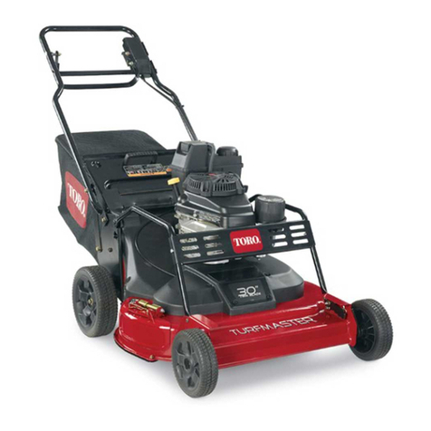
Toro TurfMaster 22205TE User manual

Toro
Toro HDX SD 2000 Series User manual

Toro
Toro Reelmaster 5610-D User manual
Toro
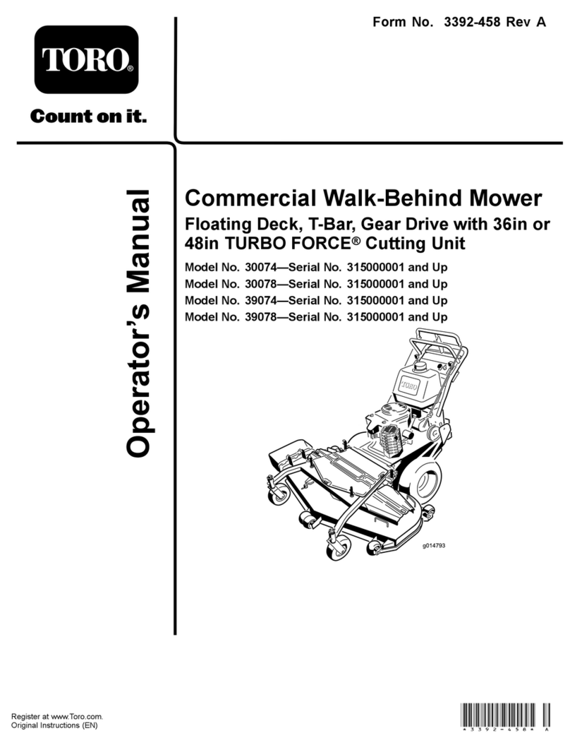
Toro 30074 User manual
Toro
Toro 30291TE User manual

Toro
Toro 72027 User manual
Toro
Toro 74410 User manual
Toro
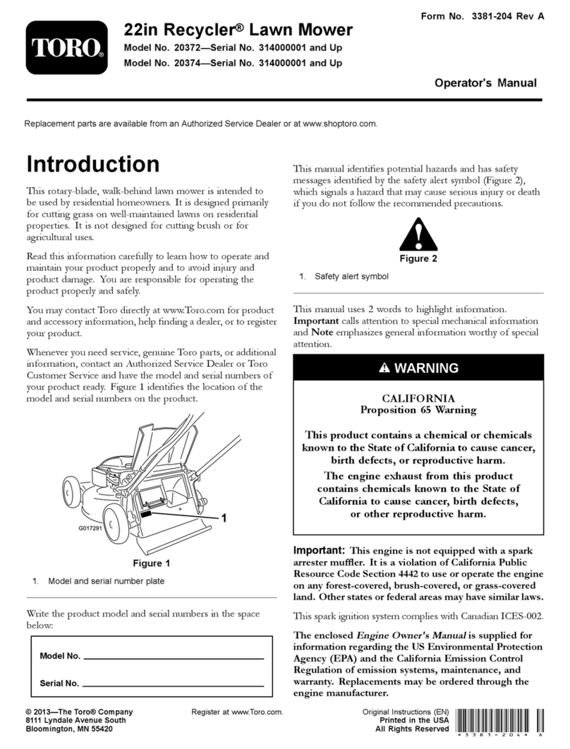
Toro Recycler 20372 User manual

Toro
Toro Reccycler User manual
Toro
Toro 30319 User manual
Toro
Toro Recycler 21442 User manual
Toro
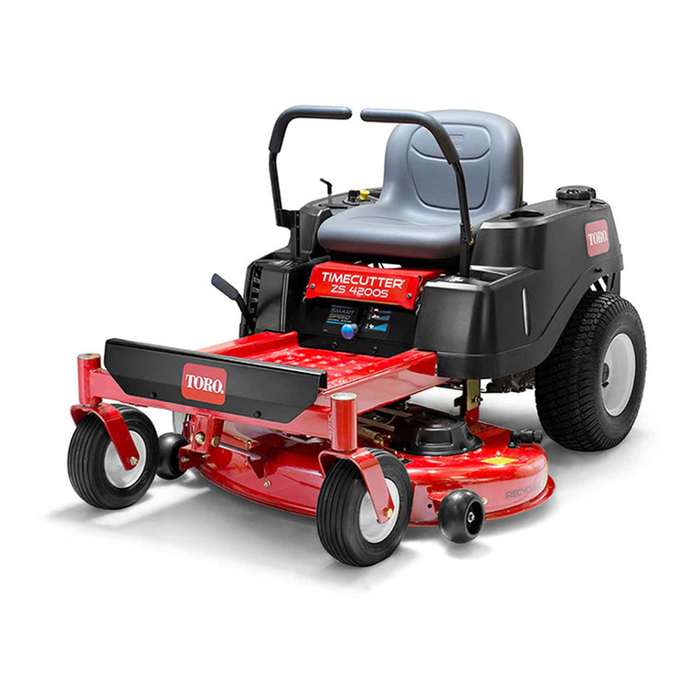
Toro TimeCutter ZS 4200S User manual

Toro
Toro Greensmaster 1610 User manual

Toro
Toro TITAN User manual
Toro
Toro Z14-38 TimeCutter Z 74402 User manual
Toro
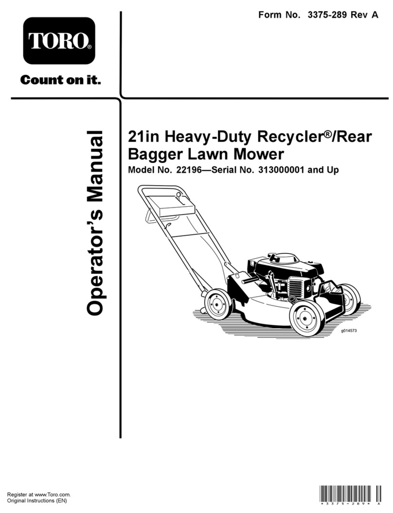
Toro 22196 User manual

Toro
Toro Reelmaster 5100-D User manual
Popular Lawn Mower manuals by other brands

DEWEZE
DEWEZE ATM-725 Operation and service manual

Weed Eater
Weed Eater 180083 owner's manual

Husqvarna
Husqvarna Poulan Pro PP185A42 Operator's manual

Better Outdoor Products
Better Outdoor Products Quick Series Operator's manual

Cub Cadet
Cub Cadet 23HP Z-Force 60 Operator's and service manual

MTD
MTD 795, 792, 791, 790 Operator's manual
