Toro Z334 Z Master Manual
Other Toro Lawn Mower manuals
Toro
Toro Z580-D Z Master 74266CP User manual
Toro
Toro 4520 User manual
Toro
Toro 73547 Manual

Toro
Toro Super Recycler 21383 User manual
Toro
Toro 79110 User manual
Toro
Toro 74406 User manual
Toro
Toro 30164 User manual

Toro
Toro Z Master G3 User manual
Toro
Toro 74704 User manual

Toro
Toro Super Recycler 20038 User manual
Toro
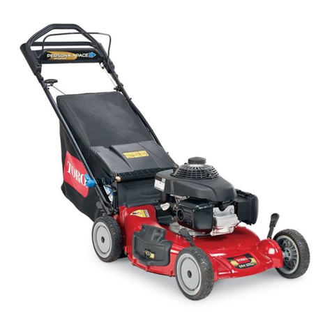
Toro Super Recycler 20382 User manual
Toro
Toro 04054 Greensmaster 800 User manual

Toro
Toro TimeCutter SS 4235 User manual
Toro
Toro 71226 User manual
Toro
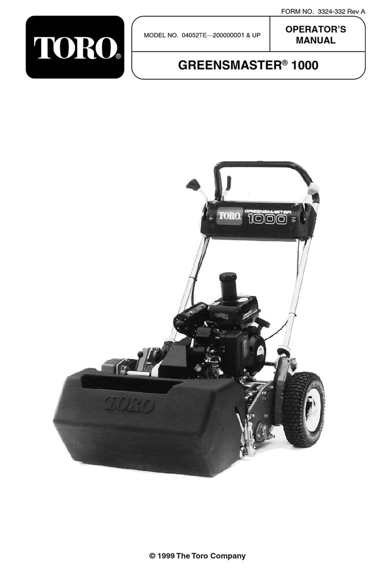
Toro 04052TE User manual

Toro
Toro groundsmaster 3240-d User manual

Toro
Toro Recyler 20333 User manual
Toro
Toro 30071 User manual
Toro
Toro 72200 User manual

Toro
Toro 74784 User manual
Popular Lawn Mower manuals by other brands

DEWEZE
DEWEZE ATM-725 Operation and service manual

Weed Eater
Weed Eater 180083 owner's manual

Husqvarna
Husqvarna Poulan Pro PP185A42 Operator's manual

Better Outdoor Products
Better Outdoor Products Quick Series Operator's manual

Cub Cadet
Cub Cadet 23HP Z-Force 60 Operator's and service manual

MTD
MTD 795, 792, 791, 790 Operator's manual
