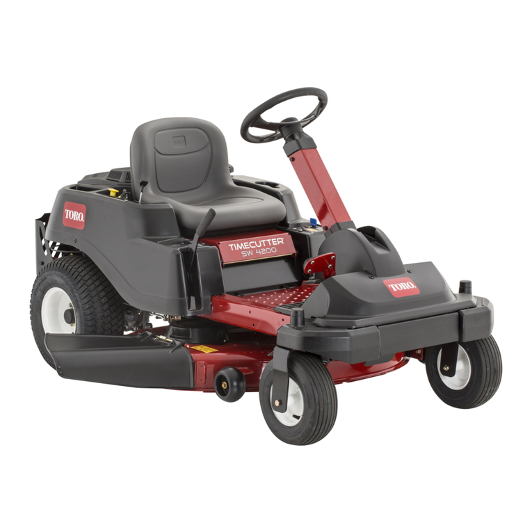
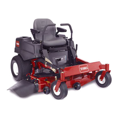
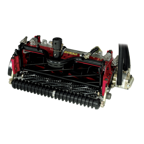
Toro 70041 User manual


e

3
TABLE OF CONTENTS
Page Page
Safe Operating Requirements - Riding ehicles 4. .
Safety Decals and Instructions 7. . . . . . . . . . . . . . . . . .
Slope Chart 8. . . . . . . . . . . . . . . . . . . . . . . . . . . . . . . . . .
Specifications 9. . . . . . . . . . . . . . . . . . . . . . . . . . . . . . . .
Loose Parts 10. . . . . . . . . . . . . . . . . . . . . . . . . . . . . . . .
Setting Up Instructions 10. . . . . . . . . . . . . . . . . . . . . . .
Install Seat 10. . . . . . . . . . . . . . . . . . . . . . . . . .
Install Steering Wheel 10. . . . . . . . . . . . . . . . .
Activating and Charging Battery 11. . . . . . . .
Before Operating 12. . . . . . . . . . . . . . . . . . . . . . . . . . . . .
Fill Crankcase With Oil 12. . . . . . . . . . . . . . . . .
Fill Fuel Tank With Gasoline 12. . . . . . . . . . . .
Controls 13. . . . . . . . . . . . . . . . . . . . . . . . . . . . . . . . . . . .
Starting and Stopping Instructions 14. . . . . . . . . . . . . .
Operating Instructions 14. . . . . . . . . . . . . . . . . . . . . . . .
BreakĆin 14. . . . . . . . . . . . . . . . . . . . . . . . . . . . .
Using Parking Brake 14. . . . . . . . . . . . . . . . . .
Adjusting HeightĆofĆCut 14. . . . . . . . . . . . . . . .
Operating Procedure 14. . . . . . . . . . . . . . . . . .
Installing Discharge Cover 15. . . . . . . . . . . . .
Side Discharging or Bagging 15. . . . . . . . . . .
Grass Deflector 15. . . . . . . . . . . . . . . . . . . . . . .
Recycler Rider Tips 16. . . . . . . . . . . . . . . . . . . . . . . . . .
Maintenance 18. . . . . . . . . . . . . . . . . . . . . . . . . . . . . . . . .
Maintenance Interval Chart 18. . . . . . . . . . . . .
Grease Front Axle Spindles and Wheels 19.
Grease Rear Axles 19. . . . . . . . . . . . . . . . . . . .
Lubricate Pivot Points 19. . . . . . . . . . . . . . . . . .
Cleaning Cooling System 19. . . . . . . . . . . . . .
Servicing Air Cleaner 20. . . . . . . . . . . . . . . . . .
Changing Crankcase Oil 20. . . . . . . . . . . . . . .
Draining Gasoline From Fuel Tank 21. . . . . . .
Replacing Spark Plug 21. . . . . . . . . . . . . . . . .
Servicing Cutter Blade 22. . . . . . . . . . . . . . . . .
Washing Underside of Mower Housing 23. .
Removing/lnstalling Mower Housing 24. . . . .
Replacing Blade Drive Belt 25. . . . . . . . . . . . .
Replacing Traction Drive Belt 26. . . . . . . . . . .
Checking/Adjusting Drive Chain 27. . . . . . . .
Adjusting Brake 28. . . . . . . . . . . . . . . . . . . . . . .
Checking Electrical Connections 28. . . . . . . .
Checking Safety Interlock System 28. . . . . . .
Preparing Mower For Storage 29. . . . . . . . . .
Wiring Diagram 30. . . . . . . . . . . . . . . . . . . . . . . . . . . . . .
Trouble Shooting 31. . . . . . . . . . . . . . . . . . . . . . . . . . . . .
Maintenance Record 33. . . . . . . . . . . . . . . . . . . . . . . . .
Warranty Back Page. . . . . . . . . . . . . . . . . . . . . . . . . . . . .
These symbols mar important instructions relating to your personal safety. To avoid possibility
of injury, read and follow such instructions carefully.
DANGER
CAUTION
When manual refers to left or right side of vehicle, it means your left or right when sitting in driver's
seat.
The engine exhaust from this product
contains chemicals known to the State of
California to cause cancer, birth defects,
or other reproductive harm.

4
SAFE OPERATING REQ IREMENTS ć RIDING VEHICLES
WARNING: Engine exhaust contains carbon monoxĆ
ide which is an odorless, deadly poison. Carbon
monoxide is also known to the State of California to
cause birth defects. Do not run engine indoors or in
an enclosed area.
GENERAL
1. This machine is capable of amputating hands
and feet and can throw objects that can cause injury
and damage. KNOW the controls and how to stop
machine quickly. READ THIS OPERATOR'S MANUAL
and instructions furnished with attachments. Read,
understand, and obey all safety messages appearĆ
ing on the machine and in the operator's manual.
LEARN from your operator's manual and from careĆ
ful E PERIENCE how to operate your equipment
correctly. Know your machine's limitations.
2. Keep hands, feet, hair and loose clothing away
from attachment discharge area, underside of mowĆ
er deck or any moving parts while engine is running.
3. The use of drugs or alcohol while operating any
equipment will place your safety in peril. Do not atĆ
tempt operation of this machine while taking drugs
or medication or while drinking alcoholic beverages.
4. Only responsible persons with mature judgment
and proper physical capabilities should be allowed
to operate this machine, and only after instruction in
the proper use of this equipment.
5. Do not allow children to operate machine.
6. Do not carry passengers.
7. The purpose of this machine is to perform work.
This equipment is not intended for sport or recreĆ
ation.
8. Do not mow when people or pets are around.
9. Clear work area of objects (wire, rocks, etc.)
which might be picked up and thrown.
10. Take all possible precautions when leaving veĆ
hicle unattended; disengage powerĆtakeĆoff, lower
attachments, shift into neutral, set parking brake,
stop engine and remove key.
11. Watch out for traffic when crossing or near roadĆ
ways.
12. Machine and attachments should be stopped
and inspected for damage after striking a foreign
object. Damage should be repaired before restarting
and operating equipment.
13. Do not change engine governor settings or
over-speed engine.
14. Wear appropriate protective clothing when operĆ
ating equipment. Long pants and substantial footĆ
wear are essential. Do not operate with bare feet or
open sandals.
15. Do not operate equipment unless properly
seated with feet on footrests or pedals.
16. Keep your eyes and mind on your machine, atĆ
tachment and the working area. Do not let other inĆ
terests distract you.
17. Safety switches are intended to stop or prevent
starting of engine to help prevent accidents.
OPERATOR SHOULD TAKE PRECAUTIONS AND
NOT RELY ENTIRELY ON SAFETY SWITCH(ES).
Check switches for proper operation before each
use.
18. Care should be used not to touch equipment or
attachment parts which may be hot from operation.
Muffler and nearby areas may exceed 150_ F. Allow
cooling to occur before attempting to maintain, adĆ
just or service.
19. Use of stereo headphones, ear protection or othĆ
er sound altering/dampening devices may limit your
ability to hear warning sounds (horns, shouts, etc.).
F EL / FIRE PRECA TIONS
20. Handle gasoline with care. It is highly flammable.
21. Use approved gasoline container. Place containĆ
er out of reach of children.
22. Use gasoline only as a fuel Ċ never as a cleaner.
23. Never remove fuel cap or add gasoline to a runĆ
ning or hot engine, or an engine that has not been
allowed to cool for several minutes after running.
24. Never fill fuel tank indoors. Wipe up spilled gasoĆ
line.
25. Open doors if engine is run in garage Ċ exhaust
fumes are dangerous. Do not run engine indoors.
26. Do not fill machine with gasoline while smoking
or when near open flame or sparks.
27. Never store equipment with gasoline in the tank
inside a building where fumes may reach an open
flame or spark.
28. Allow engine to cool before storing in any encloĆ
sure.
29. To reduce fire hazard, keep engine and attachĆ
ments free of grass, leaves or excessive grease.
30. Battery acid is a poison and can cause a burn.
Avoid contact with skin, eyes and clothes and proĆ
tect your face, eyes and clothing when working
around the battery.
31. Battery gases can explode. Keep cigarette
sparks and flames away from battery.

It is recommended that first operation of equipĆ
ment be done at a slow speed with attachment disĆ
engaged. Continue this practice until operator is
thoroughly familiar with the controls and has develĆ
oped operating skills.
Disengage all attachment clutches, set parking
brake and shift into neutral before attempting to start
engine.
Disengage power to attachment(s), set parking
brake and stop engine before leaving operator posiĆ
tion.
Disengage power to attachment(s) and stop enĆ
gine before making any repairs or adjustments.
Disengage power to attachment(s) when transĆ
porting or not in use.
Disengage attachment clutch before attempting
to remove the mower from a hole or other obstrucĆ
tion.
Disengage power to attachment(s) before backĆ
ing. Do not mow in reverse unless absolutely necesĆ
sary and then only after careful observation of the
entire area behind the machine.
LOOK behind machine to make sure the area is
clear before placing the transmission in reverse and
continue looking behind while backing.
Always back up loading ramps and tilt bed trailĆ
ers.
The parking brake is designed to hold rider in
place at rest, with engine off. Parking brake will not
restrain rider with engine running and transmission
engaged.
!
Know the terrain on which you are operating
your equipment. There are areas on which your
equipment cannot be safely operated.
Avoid operating equipment on hillsides, slopes
or rough terrain. DO NOT operate machine on hillĆ
sides or slopes exceeding 15_ (27% grade). If safety
is in doubt TAY OFF THE LOPE.
Reduce speed and exercise extreme caution on
slopes above 10_ (18% grade) to prevent tipping or
loss of control. Never mow uphill on these slopes Ċ
mow downhill only. If a steep hill must be ascended,
back up the hill, and drive forward down the hill,
keeping tractor in gear. If necessary to turn on hill,
always turn downhill.
Mow up and down the face of slopes greater
than 5_ (9% grade), never across the face. Be espeĆ
cially cautious when changing directions on all
slopes.
Operate your machine smoothly and at a ground
speed slow enough to ensure complete control at all
times. Avoid erratic operation and excessive speed.
harp turns on any terrain may cause loss of
control. Reduce speed and use caution when makĆ
ing sharp turns.
Do not stop or start suddenly when going uphill
or downhill. Avoid uphill starts. If machine is stopped
going up a slope, turn the attachment off and back
slowly down the slope keeping the machine in gear.
Do not stop or change gears (speed) on slopes.
Know the terrain on which you are working. Find
hidden obstacles by walking through and inspecting
the area prior to operating your equipment in that
area. Plainly mark obstacles, such as rocks, ruts or
holes and stay well clear of these obstacles when
operating.
While operating, stay alert for holes, rocks or
roots, which may cause damage to equipment or
upset. Keep at least 3 ft. away from dropĆoffs,
ditches, creeks, culverts, washouts and public highĆ
ways.
Exercise care when mowing around a fixed obĆ
ject to prevent the equipment or attachment from
striking the object. When mowing never deliberately
run over any foreign object.
Areas wet with dew, rain or snow will be more
slippery than when dry. Areas covered with loose
gravel are more slippery than firm dry ground. GreatĆ
er stopping distances are required in these slippery
areas.
Learn to expect changes in operating conditions.
Adding or removing attachments or weight to your
equipment will make your machine perform differentĆ
ly. Rain, snow, loose gravel, wet grass, etc., change
the tractive conditions of the terrain requiring
changes in your operating technique, which may
include a decision not to operate on that terrain.
Use care when pulling loads or using heavy
equipment.
A. Use only approved drawbar hitch points.
B. Limit loads to those you can safely control.
C. Do not turn sharply. Use care when backing.
D. Use counterweight(s) or wheel weights when
suggested in operator's manual.
When using attachments never direct discharge
of material toward bystanders nor allow anyone near
vehicle while in operation.
When using machine with mower:
A. Mow only in daylight or in good artificial light.
B. Never make a cutting height adjustment while
engine is running if operator must dismount to
do so.
C. Shut engine off and wait for all moving parts to
stop before unclogging chute.
D. Check blade mounting bolts for proper tightĆ
ness at frequent intervals.
Keep hands and feet away from rotating blade(s)
underneath mower deck. Never place foot on
ground when mower is engaged or when mower is
in motion.
DO NO operate mower attachment without the
chute deflector or complete bagger in place.
Exercise care while maneuvering with grass
catcher. Front to rear stability may change.
Keep all nuts, bolts, fasteners and screws tight
to be sure equipment is in safe working condition
and check them frequently. Repair or replace worn,
damaged, distorted or broken parts as needed.
Keep vehicle and attachments in good operating
condition and keep safety devices in place and
working.
Under normal usage, grass catcher bag material
is subject to deterioration and wear. It should be
checked frequently to determine need for bag reĆ
placement.
Use only genuine oro Wheel Horse replacement
parts to ensure that original standards are mainĆ
tained.
Shields, deflectors, switches, blade controls and
other safety devices must be in their proper position
and functional.
Do not operate without muffler or tamper with
the exhaust system. Damaged mufflers or optional
spark arrestors can create a fire hazard. Periodically
inspect and replace if necessary.
If equipment begins to vibrate abnormally, disenĆ
gage power to attachments and stop engine at
once. Repair any damage before starting or continuĆ
ing operation.
Periodically inspect all shafts, levers, friction deĆ
vices and other moving parts subject to wear. Make
required adjustment or replace these parts if damĆ
aged, distorted or broken, or as soon as wear affects
the normal operation of the vehicle or attachment.
DO NO operate equipment that is not functioning
properly.
A separate parts manual is available for your oro Wheel Horse equipment. o obtain a parts manual, write to:
he oro Company
8111 Lyndale Avenue South
Bloomington, MN 55420-1196

" !
#%& $ '
"
#%& $
#%& $
"
#%& $
#%& $
!
#%& $

8
10_ SLOPE CHART
Read all safety instr ctions on pages 3-6

.'%%/ 0. 00,+ +%'+# Four cycle engine has
output of 8 hp (6 W) @ 3600 rpm and 12.7 ft/lb
(17.2 N·m) torque @ 2500 rpm. Displacement is
19.44 cubic inches (319 cc). Crankcase oil capacity
is approximately 36 oz. (1.06 l). Correct spark plug is
a Champion RJĆ19LM. Recommended spark plug air
gap is 0.030 of an inch (0.762 mm).
,3#. ,1/'+% Full floating, stamped steel housĆ
ing has spiral grass chamber, kickers, cover and
ring. Width of cut is 25 inches (63.5 cm). Cast iron
spindle housing with shaft is supported by sealed
ball bearings. Blade pulley is driven by a belt from
the engine pulley.
100#. ) "# Single blade is 25 inches (63.5 cm)
long, made of 7 gauge (2.72 mm) carbon steel and
heat treated for hardness.
) "# '- -##" Tip speed of blade is 17,420 ft/
min @ 3400 engine rpm.
#'%&0,$10 +%# Adjustable to five approxiĆ
mate range settings: 1-1/2 inches to 3-1/2 inches.
. +/*'//',+ Transmission has five speeds forward
and one for reverse. Heat treated, sintered metal
gears are enclosed in a permanently lubricated (EP
Lithium grease), die cast aluminum housing.
'$$#.#+0' ) Sintered powdered metal bevel gears
are enclosed in a permanently lubricated (Shell Epro
71030 grease), steel housing.
. !0',+ .'2# Drive system has an A" section v-
belt from engine pulley to transmission input pulley.
A no. 40 chain joins transmission output sprocket
with differential sprocket.
.,1+" -##" +%'+# .-*
1st gear - 1.4 mph
2nd gear - 2.1 mph
3rd gear - 3.2 mph
4th gear - 4.1 mph
5th gear - 4.7 mph
Rev. - 1.6 mph
&##)/ +" '.#/ The front 11 x 4.00Ć5 and the rear
13 x 5.00Ć6 tubeless, pneumatic turf tires are
installed on demountable stamped steel wheels.
Recommended pressure for front and rear tires is
10-14 psi. All tires must be equally inflated to enĆ
sure a level cut.
1#) +( Capacity is 4 quarts (3.7 l).
0##.'+% 13 inch (33 cm) diameter steering wheel.
&.,00)# ,+0.,) Control is located on right side of
seat body. Hand-operated throttle control connects
to and operates carburetor-mounted throttle and
choke. Control has three positions: SLOW, FAST
AND CHO E.
. +/*'//',+ # . &'$0 Single lever, in-line shiftĆ
ing with Z pattern.
)10!& #" ) Foot-operated pedal is located at left
front side of rider. Depressing clutch pedal moves
idler pulley away from traction drive belt, which disĆ
engages the traction drive.
. (# #" ) Foot operated pedal is located at right
front side of rider. Depressing brake pedal engages
a disk brake on side of transmission.
.('+% . (# ,+0.,) Control is located at right
front of center channel. Engage parking brake by
moving control to the left while brake pedal is deĆ
pressed; then release pedal. To disengage parking
brake, push brake pedal down so parking brake leĆ
ver moves back to its normal released position.
) "# ,+0.,) Control is mounted on front of seat
body. Control has two positions: ENGAGE and DISĆ
ENGAGE. Interlock switch prevents engine from
starting when control is in the ENGAGED position.
When control is in DISENGAGE position, the blade
brake is applied and blade belt idler pulley is disenĆ
gaged. By contrast, idler pulley is engaged with
blade belt when control is in the ENGAGE position:
blade brake is released.
%+'0',+ 3'0!& Switch is located on right side of
seat body. Switch has three positions: ON, OFF and
START.
#'%&05$510 ,+0.,) Control is mounted on front
of seat body.
#+#. ) '*#+/',+/ --.,4
Wheel Base -41 in (104 cm)
Wheel Tread -28 in (71 cm) front outside to outĆ
side
Overall Length -52 in (132 cm)
Overall Height -38 in (.97 m)
Overall Width -32 in (81 cm)
Dry Weight -305 Ib (1.6 kg)
Specifications and design subject to change without notice.

10
LOOSE PARTS
Note: Carefully remove rider and other parts from carton. Use chart elow to ensure all parts have een
shipped.
Seat 1
Clamp 1
Washer 4
Capscrew 4
Steering Wheel 1
Roll Pin 1
Spacer 1
Bolt 1/4-20 x 3/4" 2
Wingnut 1/4-20 2
Key 1 Use in ignition switch.
Operator's Manual 1 Read efore operating rider.
DESCRIPTION QTY USE
Install Seat, page 10.
Install Steering Wheel, page9.
Install Battery Ca les, page 10.
SETTING UP INSTRUCTIONS
INSTALL SEAT
1. Position seat onto seat ase, inserting seat
switch ca le thru slot and aligning mounting holes
(Fig. 1).
F gure 1
1
2
3
4391
5
2. Slide wire clamp over seat switch wire (Fig. 1).
3. Using left front mounting slot in seat ase, looseĆ
ly secure wire clamp and seat to seat ase with a
capscrew and lock washer (Fig. 1).
4. Mount seat to seat ase with (3) remaining capĆ
screws and lock washers.
Note: Seat may e adjusted for operator comfort y
positioning seat as desired in seat ase slots.
5. Tighten all capscrews.
6. Insert seat switch connector into wire harness
connector.
INSTALL STEERING WHEEL
1. Slip spacer onto steering shaft until groove in
spacer fits over roll pin in shaft (Fig. 2).
F gure 2
1581
1
2
3

Slip steering wheel onto steering shaft, aligning
the steering wheel mount hole with shaft mounting
hole.
04' Steering wheel insert (Fig. 2) should be readĆ
able from operator's position on rider with wheels
turned straight ahead.
Insert a drift punch partially through the holes to
maintain alignment and insert the roll pin in the opĆ
posite side.
Drive the roll pin in until flush with the outside of
the steering wheel.
"
The battery must be removed from the rider so it can
be filled with electrolyte and charged. Bulk electroĆ
lyte with 1.260 specific gravity must be purchased
from a local battery supply outlet. Remove the batĆ
tery and activate it as follows:
!'#2 3#('49 )0))-'3 #/& 25$$'2 )-06'3
7*'/ 702,+/) 7+4* '-'%420-94' *#2)' 4*'
$#44'29 +/ # 7'-- 6'/4+-#4'& 1-#%' 30 )#3'3
120&5%'& 7*+-' %*#2)+/) %#/ &+33+1#4'
+/%' 4*' )#3'3 #2' '81-03+6' ,''1 01'/
(-#.' #/& '-'%42+%#- 31#2, #7#9 (20. 4*' $#4:
4'29 &0 /04 3.0,' #53'# .#9 2'35-4 +( 4*'
)#3'3 #2' +/*#-'& /1-5) %*#2)'2 (20.
'-'%42+%#- 054-'4 $'(02' %0//'%4+/) 40 02 &+3:
%0//'%4+/) %*#2)'2 -'#&3 (20. $#44'29 10343
Remove wing nut securing battery hold downs to
rider chassis (Fig. 3).
Remove battery from chassis and set it aside.
Remove filler caps from battery and slowly fill
each cell until electrolyte is just above the plates. To
obtain best results, let battery sit for 20 minutes.
Then add electrolyte to the maximum capacity (fill
ring).
Leave filler caps off and connect a 3Ć4 amp batĆ
tery charger to battery posts. Charge battery at a
rate of 4 amperes or less for 4 hours (12 volt).
0 /04 06'2(+-- $#44'29 -'%420-94'
7+-- 06'2(-07 0/40 04*'2 1#243 #/& 3'6'2' %0220:
3+0/ #/& &'4'2+02#4+0/ 7+-- 2'35-4
hen battery is charged, disconnect charger
from electrical outlet and battery posts.
Slowly add electrolyte to each cell until level is
up to fill ring. Reinstall filler caps.
04' Once battery is in service, distilled water only
should be added; never add more electrolyte.
Reinstall the battery with terminal posts toward
the rear of the machine and vent tube thru hole in
frame (Fig. 3).
Reinstall battery hold downs.
Reinstall the positive cable to the positive (+)
terminal and the negative cable (black) to the negaĆ
tive (-) terminal of the battery and secure with capĆ
screws and wing nuts (Fig. 3).
+)52'
1589
1
1
3
2
Negative -
Positive +

12
BEF RE PERATING
FILL CRANKCASE WITH IL
The rider is shipped from the factory without oil in
the crankcase. Therefore, before trying to start enĆ
gine, oil must be added to the crankcase.
IMP RTANT: CHECK IL LEVEL EVERY TIME
Y U FILL GAS TANK. Initially, change oil after the
first 2 hours of operation; thereafter, under norĆ
mal conditions, change oil after every 25 hours of
operation. However, change oil more frequently
when engine is operated in dusty or dirty condiĆ
tions.
1. Move rider to a level surface to ensure accurate
oil level reading and raise seat to expose oil dipstick.
2. Clean the area around oil dipstick so foreign
matter cannot enter fill tube when plug is removed.
3. Remove dipstick from fill tube (Fig. 4).
4. Crankcase capacity is approx. 36 oz. (1.06 l).
Amount of oil required to fill crankcase may be less
than 36 oz. due to oil remaining in engine. D N T
VERFILL.
Figure 4
1582
1
2
5. Slowly pour oil into crankcase (Fig. 4). The enĆ
gine uses any high quality detergent oil having the
American etroleum Institute Ċ A I Ċ service clasĆ
sification" SF or SG. Oil viscosity Ċ weight Ċ must
be selected according to anticipated ambient temĆ
perature.
A. Above +40_F Ċ Use SAE 30.
B. 0_F to 100_F Ċ Use SAE 10W-30.
C. Below +20_F Ċ Use SAE 5W-30.
DO NOT USE SAE 10W40 OIL.
6. Rock the rider gently to release any air that may
be trapped in crankcase. Screw dipstick fully into fill
tube; then remove it and make sure that oil level is
up to FULL mark on dipstick (Fig. 4). If level is low,
add only enough oil to bring level up to FULL mark.
7. Install dipstick into fill tube. Wipe up any oil that
may have spilled.
FILL FUEL TANK WITH GAS LINE
Because gasoline is flammable, caution must
be used when storing or handling it. Do not fill
fuel tank while engine is running, hot or when
machine is in an enclosed area. Vapors may
build up and be ignited by a spark or flame
source many feet away. D N T SM KE
while filling the fuel tank to prevent the possiĆ
bility of an explosion.
Always fill fuel tank outside and wipe up any
spilled gasoline before starting engine. Use a
funnel or spout to prevent spilling gasoline,
and fill tank to about 1/2 inch (13 mm) below
the filler neck. Store gasoline in a clean, safeĆ
ty-approved container and keep the cap in
place on container. Keep gasoline in a cool,
wellĆventilated place; never in an enclosed
area such as a hot storage shed. To ensure
volatility, do not buy more than a 30 day supĆ
ply of gasoline.
Gasoline is a fuel for internal combustion enĆ
gines; therefore, do not use it for any other
purpose. Since many children like the smell of
gas, keep it out of their reach because the
fumes are explosive and dangerous to inhale.
DANGER
THE TORO COM ANY STRONGLY RECOMMENDS
THE USE OF CLEAN, FRESH UNLEADED REGĆ
ULAR GASOLINE IN TORO GASOLINE OWERED
RODUCTS. UNLEADED GASOLINE BURNS
CLEANER, EXTENDS ENGINE LIFE, AND ROĆ
MOTES GOOD STARTING BY REDUCING THE
BUILDĆU OF COMBUSTION CHAMBER DE OSITS.
LEADED GASOLINE CAN BE USED IF UNLEADED
IS NOT AVAILABLE.
Toro also recommends that Toro Stabilizer/ConditionĆ
er be used regularly in all Toro gasoline powered
products during operation and storage seasons.
Toro Stabilizer/Conditioner cleans the engine during
operation and prevents gum-like varnish deposits
from forming in the engine during storage.
N TE: NEVER USE METHAN L, GAS LINE C NĆ
TAINING METHAN L, GAS H L C NTAINING
M RE THAN 10% ETHAN L, PREMIUM GASĆ
LINE R WHITE GAS BECAUSE ENGINE FUEL
SYSTEM DAMAGE C ULD RESULT.

!2
2
! 2
!
!
!
2
! 2
2
Clean area around fuel tank cap so foreign matĆ
ter cannot enter tank when cap is removed.
Remove cap from fuel tank and fill tank with unĆ
leaded regular gasoline. hen reinstall fuel tank cap.
Wipe up any gasoline that may have spilled.
%". ()&/ (Fig. 5)Ċ he transmission has five forĆ
ward speeds, neutral, and reverse. he gear shift
lever is located on right side of operator. An interĆ
lock switch, which prevents engine from being
started when transmission is in gear, is mounted on
top of transmission.
)'0.%
1. Blade con rol
2. Heigh -of-cu conĆ
rol
3. Igni ion swi ch
4. Thro le con rol
5. Gear shif
1583
1
2
5
3
4
+0/#( %$"+ (Fig. 6)ĊFoot-operated clutch pedal
is used in conjunction with gear shift. Depress clutch
pedal fully when shifting gears. Depress clutch pedal
whenever brake is used.
."*% %$"+ (Fig. 6)ĊFoot-operated brake pedal
must be depressed to slow down or stop the rider.
When pedal is depressed, a caliper engages the
brake disc on the side of the transmission. Always
depress clutch pedal when using brake.
".*),' ."*% (Fig. 6)ĊParking brake must be
used in conjunction with brake pedal. When pedal is
depressed and end of parking brake lever holds
brake pedal in depressed position, a caliper enĆ
gages the brake disc at side of transmission.
)'0.%
1. Parking brake
2. Clu ch pedal
3. Brake pedal
1584
1
3
2
+"$% -,/.-+ (Fig. 5)ĊBlade control engages and
disengages the cutter blade. An interlock switch preĆ
vents engine from starting when control is in the ENĆ
GAGE position. Engine will start when control is in
the DISENGAGE position only.
(.-//+% -,/.-+ (Fig. 5)Ċ hrottle control connects
to and operates carburetor-mounted throttle and
choke. Control has three positions: SLOW, FAS and
CHOKE.
%)'(/-&0/ (Fig. 5)ĊHeight-of-cut control
varies the cutting height from approx. 1-1/2 to
3-1/2 inches in five increments.
+',)/)-, 1)/#( (Fig. 6)ĊSwitch has three positions:
ON, OFF and S AR .

14
STARTING AND STOPPING INSTRUCTIONS
Note: Make sure wire is installed on spark plug, batĆ
tery is activated, and cables are installed on battery
posts.
1. Engage the parking brake (Fig. 6): refer to using
Parking Brake, page 14.
2. Move gear shift into neutral and blade control
into DISENGAGE detent (Fig. 5).
Note: An interlock switch on the transmission and
blade control prevents engine from starting unless
the operator is sitting on the seat, the gear shift is in
neutral and the blade control is in the DISENGAGE
detent.
3. Move throttle control to CHOKE position (Fig. 5)
when starting a cold engine. However, a hot engine
requires no choking. Move throttle to FAS position
for starting.
4. Rotate ignition key (Fig. 5) to S AR position.
When engine starts, release the key and move throttle
between FAS and SLOW if choke was used for startĆ
ing. Operate the rider with throttle control in FAS (full
throttle) position for best performance.
TO STOP
1. o stop the engine, depress clutch pedal, shift into
neutral and engage parking brake. Move blade control
into DISENGAGE detent, move throttle control to
SLOW and allow engine to idle a short period before roĆ
tating ignition key to OFF. Rotate ignition key to OFF
and wait for all moving parts to stop before getting off
the seat.
OPERATING INSTRUCTIONS
BREAKĆIN
he engine requires no special breakĆin other than
checking the oil level each time you fill the gas tank
and changing the oil after the first two hours of opĆ
eration. Some oil consumption will be noticed during
break in, but will improve as used. Operate the transĆ
mission in all gears to ensure that the drive system is
functioning correctly. After the first five hours of opĆ
eration, check the condition and adjustment of the
drive chain and belts.
USING PARKING BRAKE
CAUTION
If the engine stalls or must be stoppe while
operating on a hill or slope, the engine must be
shut off an parking brake engage .
1. Depress brake pedal fully.
2. Move parking brake control to the left and reĆ
lease brake pedal until it contacts end of parking
brake lever (Fig. 6).
3. o release the parking brake, depress brake
pedal (Fig. 6), which will allow parking brake lever to
return to its disengaged position. hen release brake
pedal.
IMPORTANT: Disengage parking brake before
shifting into gear to commence operation. If the
ri er is riven when parking brake is engage ,
accelerate brake wear will result.
ADJUSTING HEIGHTĆOFĆCUT
he heightĆofĆcut may be set in one of five positions:
1Ć1/2 inches to 3-1/2 inches.
1. Move blade control into DISENGAGE detent
(Fig. 5).
2. Move heightĆofĆcut control (Fig. 5) into desired setĆ
ting.
3. o engage blade for cutting, slowly move blade
control into ENGAGE detent.
OPERATING PROCEDURE
1. Move blade control into DISENGAGE detent.
2. Start the engine: refer to Starting/Stopping
Instructions, page 14.
IMPORTANT: When ri er is use for the first time,
operate the transmission in all gears to ensure
that rive system is functioning correctly an beĆ
come familiar with the controls an operating
characteristics. Also check con ition of the rive
chain an belts an make any a justments that
may be require .
3. Depress clutch pedal and shift transmission into
1st gear. hen release pedal slowly until traction
drive engages.
IMPORTANT: To avoi a jerky start an putting a
heavy loa on the transmission, move throttle to
slow spee an release clutch pe al slowly. If
shifting into reverse gear is ifficult, jog clutch
pe al in an out to get gears to mesh. Do not
force the gear shift because amage may result.
Shoul you encounter a jerking or grabbing
con ition uring operation, contact your local AuĆ
thorize TORO Service Dealer for assistance.
4. o engage blade for cutting, move height-of-
cut control to the desired setting. Move the throttle to
FAS position. Start the blade whirling by slowly
moving blade control into ENGAGE detent.

!
0 "60*% -033 0' $0/420- "-7"83 $0.& 40 "
$0.1-&4& 3401 #&'02& 3)*'4*/( (&"23 "/%
3-07 %07/ 7)&/ 452/*/( #"$,*/( "/%
$)"/(*/( %*2&$4*0/ 00, #&)*/% 4)& 2*%&2 40
&/352& "2&" *3 $-&"2 #&'02& #"$,*/(
To stop en ine, in sequence, depress clutch and
brake pedals, move blade control into DISENGAGE
detent, ear shift into neutral, and throttle to SLOW;
rotate key to OFF position after allowin en ine to
idle a short period of time.
*(
When you do not want to ba clippin s or side disĆ
char e, the plastic dischar e cover must be installed
under the rass deflector.
52/ &/(*/& 0'' "/% 7"*4 '02 "-- .06*/( 1"243
40 3401 &.06& 31"2, 1-5( 7*2& '20. 31"2,
1-5(
!
Lift rass deflector and position plastic dischar e
cover over lon bolt.
Place metal tab on lon bolt as shown in
Fi ure 7.
Lower rass deflector and make sure ed e of
deflector is secured under metal tab.
Usin the win nut, ti hten securely the metal
tab, rass deflector and plastic dischar e cover in
place.
)& .&4"- 4"# .534 #& 53&% 40 '"34&/ 4)&
(2"33 %&'-&$402 40 4)& 1-"34*$ %*3$)"2(& $069
&2 ' 4)& (2"33 %&'-&$402 *3 /04 '"34&/&% 3&9
$52&-8 40 4)& %*3$)"2(& $06&2 4)& %*3$)"2(&
$06&2 $05-% $0.& -003& %52*/( 01&2"4*0/
"/% %*3$)"2(&% ."4&2*"- $05-% $"53& 1&29
30/"- */+528
!
If the plastic dischar e cover is ever removed
in order to side dischar e or ba , be sure to save
the metal tab with the plastic dischar e cover for
possible future reinstallation.
*(52&
1. Wing nut
2. Long bolt
3. Plastic discharge cover
4. Metal tab
5. Grass deflector
1
23
4
5
To side dischar e or use ba in attachment, reĆ
move the win nut and metal tab securin the plastic
dischar e cover to the rass deflector and mower
housin . 9
! *( Save
the dischar e cover, win nut and metal tab for posĆ
sible future reinstallation.
If you no lon er wish to side dischar e or ba clipĆ
pin s, the dischar e cover can be reinstalled by seĆ
curin it the mower housin and rass deflector
with the win nut and metal tab.
: When the dischar e cover is in place,
it .534 be secured to the rass deflector with the
metal tab and win nut.
2&.06& 4)& (2"33 %&'-&$402 *(
'20. 4)& .07&2 )053*/( ' 4)& %*3$)"2(& $069
&2 5/%&2 4)& (2"33 %&'-&$402 *3 2&.06&% */ 029
%&2 40 3*%& %*3$)"2(& 02 #"( 4)& (2"33 %&'-&$9
402 2054&3 %*3$)"2(&% ."4&2*"- %07/ 407"2%
4)& 452' ' 4)& %&'-&$402 *3 &6&2 %"."(&% 2&9
1-"$& *4 !*4)054 4)& %&'-&$402 02 $0.1-&4&
(2"33 $"4$)&2 "33&.#-8 .05/4&% */ 1-"$&
%*3$)"2(&% ."4&2*"- $05-% $"53& 1&230/"- */9
+528 02 #-"%& $0/4"$4 $05-% 0$$52
!

16
RECYCLERr RIDER TIPS
RECYCLERr RIDER FEATURES
Your Toro Recyclerr rider has a new and completely
different cutting concept. It leaves your lawn with a
bagged look without bagging clippings.
The rider is equipped with special parts (Fig. 8)
which increase your rider's ability to cut and recut
grass clippings, leaves, and other yard debris into
tiny particles which are injected down into the grass.
These parts are:
DDeck ring
DSpecial blade
DDischarge cover
DFour special kickers" positioned on the underĆ
side of the mower deck in strategic positions. (A fifth
kicker is molded into the discharge cover.)
F gure 8
394
3
1
4
3
2
3
5
TIPS FOR CUTTING GRASS
Even with the Recyclerr rider, you may encounter
conditions where it is not possible to incorporate all
of the grass clippings or leaves all of the time into
the grass. Follow these instructions for the best cutĆ
ting results and lawn appearance:
DAlways use FAST (full) throttle when mowing.
DMaintain a sharp blade throughout the cutting
season. A sharp blade cuts cleanly and without tearĆ
ing or shredding the grass blades like a dull blade.
Tearing and shredding causes the grass to turn
brown at the edges which impairs growth and inĆ
creases susceptibility to diseases. About every 30
days, remove the wire from the spark plug and
check the cutter blade for sharpness. File down any
nicks on blade to restore its sharp edge.
DClean any residue from the underside of the rider
housing and kickers after each use. If residue is alĆ
lowed to build up in rider housing and on kickers,
cutting performance may be unsatisfactory.
DVery long or extremely wet grass can be cut, but
specific operating techniques must be used. Start by
setting height-of-cut in the highest position. sing
1st gear and maximum throttle speed, move into the
grass and cut a swath that is only half as wide as the
mower housing. If side discharging, direct grass clipĆ
pings toward area that was cut previously. Stop forĆ
ward movement occasionally to allow discharge area
to clear itself. Cutting too much grass may clog the
mower housing and discharge area. If mower housĆ
ing does clog, shut engine off, disengage blade and
remove the obstruction with a stick.
Before remov ng any obstruct on from mower
hous ng, move blade control nto DISENGAGE
detent, depress clutch and brake pedals, sh ft
nto neutral and turn gn t on key to OFF pos Ć
t on. Remove w re from spark plug to prevent
the poss b l ty of acc dental start ng.
DANGER
DWhen the rider is used to cut a lawn for the first
time, cut grass slightly longer than normal to ensure
that cutting height of mower housing will not cause
scalping, which could result from severe undulations
of the ground. In general, however, the cutting height
used in the past is probably the best one to use.
When cutting grass over six inches tall, you may
want to cut the lawn twice to hide clippings down in
the grass.
DIf the grass is ever allowed to grow slightly longĆ
er than normal, or if it contains a high degree of
moisture, raise cutting height higher than usual and
cut the grass at this setting. Next, cut the grass
again using the lower, normal setting. This method of
cutting long grass results in an even distribution of
clippings and an acceptable quality-of-cut.
DIn the heat of the summer, it is best to cut only
about 1/3 of the grass blade. Cutting below the 3rd
setting is not recommended unless grass is sparse
or it is late fall when grass growth begins to slow
down.
DIf the cutting width of the rider is wider than the
mower previously used, raise heightĆofĆcut setting
one notch to ensure undulations in turf are not cut
too short.
DMOWING IN EXTREME CONDITIONSĊAir is reĆ
quired to cut and recut grass clippings in rider housĆ
ing, so do not set height-of-cut too low or totally
surround housing by uncut grass. Always try to have
one side of the rider housing free from uncut grass,
allowing air to be drawn into housing. When making
an initial cut thru center of uncut area, operate rider
at a slower speed and back up if rider starts to clog.

r
DTOPPING RIDERĊIf forward motion of rider
has to be stopped while cutting, a clump of grass
clippings may be deposited on lawn. Follow this proĆ
cedure for stopping while cutting:
A. With blade engaged, move onto a previously cut
area.
B. Raise deck one or two height-of-cut settings
while driving rider forward and deck is in operaĆ
tion.
C. Depress clutch and brake pedals, move throttle
control lever to LOW position, disengage mowĆ
er and rotate ignition key to OFF.
DMOW AT PROPER INTERVAL ĊUnder most
normal conditions you'll need to mow approximately
every 4-5 days. But remember, grass grows at difĆ
ferent rates at different times. This means that in orĆ
der to maintain the same height-of-cut, which is a
good practice, you'll need to cut more frequently in
early spring; as the grass growth rate slows in mid
summer, cut only every 8-10 days. If you are unable
to mow for an extended period due to weather
conditions or other reasons, mow first with the
height-of-cut at a high level; then mow again 2-3
days later with a lower height setting.
DAlternate mowing direction. This helps disperse
clippings over lawn for even fertilization.
DIDE DI CHARGING OR BAGGINGĊTo side
discharge or use bagging attachment, remove the
wingnut and metal tab securing the plastic discharge
cover to the grass deflector.
4
"1"- -")+1" /%" $-.. !"#(" /+- &$
#-+) /%" )+2"- %+0.&*$ # /%" !&. %-$"
+1"- 0*!"- /%" $-.. !"#(" /+- &. -")+1"!
&* +-!"- /+ .&!" !&. %-$" +- $ /%" $-..
!"#(" /+- -+0/". !&. %-$"! )/"-&( !+2*
/+2-! /%" /0-# # /%" !"#(" /+- &. "1"- !)4
$"! -",( " &/ &/%+0/ /%" !"#(" /+- +-
+),("/" $-.. / %"- ..")(3 )+0*/"!
&* ,( " !&. %-$"! )/"-&( +0(! 0."
,"-.+*( &*'0-3 +- (!" +*/ / +0(! + 0-
The Recyclerr rider's special features reduce clipĆ
ping size, thus decreasing amount of grass to be
disposed of and number of times bagger will have to
be emptied.
+/" When bagger is full, mower will begin to inject
clippings down into the grass.
If the lawn appearance is not satisfactory after mowĆ
ing, try one of the following:
Dharpen the blade.
DRaise the height-of-cut setting on your mower.
DCut your grass more frequently.
DOverlap cutting swaths instead of cutting a full
swath with each pass.
DMow across the marginal areas a second time.
In the fall, you can cut your leaves up into finely cut
particles and inject the particles down into the grass.
When spring arrives, the leaf particles will have deĆ
composed and restored valuable nutrients to the
soil.
DWhen cutting is complete, always be sure that
50% of the lawn shows through the finely cut leaf
cover. This may require one or more passes over the
leaves.
DIf there are more than five inches of leaves on
lawn, raise the deck one or two notches higher. This
makes it easier to feed leaves under mower deck.
DIf leaves are not cut up finely enough to be hidĆ
den down in the grass, make a second pass 90_to
the first pass.
DIf you cut up a lot of oak leaves, you might want
to add lime to your grass in the spring. Lime reduces
the acidity of oak leaves.

Change Oil (Initial) X
Change Oil (Periodic) X X
Check Sa ety Interlock X X X X Be ore each use
Check Cutter Blade X X X
Check Brake X X X
Grease Front Axle Spindles X X More o ten
Lubricate Pivot Points X X in dusty,
Service Air Cleaner X X dirty,
Check Spark Plug X X X conditions.
Check Blade Drive Belt X
Check Traction Drive Belt X
Check Drive Chain X X X More o ten
Drain Gasoline X in dusty,
Clean Outside o Engine X X dirty,
Clean Mower Housing X X conditions.
Clean Blower Screen On Engine X X X
Paint Chipped Sur aces X
Replace Interlock Switches X
',)
*
',)*
+')
)-"
()"&
)-"
)* '+*
' ()-&+ "&+$ *+)+"& ' +! & "&
.!"$ ()')%"& %"&+&& *!,+ & "& '
)%'- #/ )'% " &"+"'& *."+! & (,$$ .")
' *()# ($, " # *,) .") '* &'+
'&++ ($, "&+$$/
" ,)
1585
12

" !
he front axle spindles and wheels must be lubriĆ
cated after every 25 hours of operation; however,
lubricate more frequently when conditions are dusty
or sandy.
Wipe grease fittings on spindles and wheels
(Fig. 10) with a clean rag. If there is paint on front of
fittings, scrape it off.
Lubricate both axle spindles w/No. 2 general
purpose grease (Fig. 10). Continue to pump grease
until it oozes out the spindle. Wipe up any excess
grease.
Lubricate both front wheels w/No. 2 general purĆ
pose grease (Fig. 10). Pump grease gun about four
times. Wipe up any excess grease.
&%('$
1586
"
he rear wheels should be removed and axles
greased once a year to prevent the formation of rust
and to simplify future wheel removal.
he mechanical pivot points on the rider must be
lubricated after every 25 hours of operation; howevĆ
er, lubricate more frequently when conditions are
dusty or sandy.
o lubricate all the mechanical pivot
points, the rider must be tipped on its rear end. HowĆ
ever, before the rider is tipped, drain all gasoline
from fuel tank and oil from crankcase. Also remove
battery so acid does not spill on the rider.
Drain gasoline from fuel tank: refer to Draining
Gasoline From Fuel ank, page 21.
Drain oil from crankcase: refer to Changing
Crankcase Oil, steps 1Ć6, page 20.
Remove battery from chassis: refer to Activating
and Charging Battery, page 11.
Shift transmission into 1st gear and engage
parking brake.
ip rider up and onto its rear end.
Remove mower housing from rider chassis: refer
to Removing/Installing Mower Housing, steps 1Ć10,
page 24.
Lubricate all mechanical pivot points on rider
and mower housing with light oil.
Install mower housing onto rider chassis: refer to
Removing/Installing Mower Housing, page 24.
ip rider back to its normal operating position.
Fill crankcase with oil: refer to Fill Crankcase
With Oil, page 12.
Fill fuel tank with gasoline: refer to Fill Fuel ank
With Gasoline, page 12.
Install the battery: refer to Activating and ChargĆ
ing Battery, page 11.
#
Clean cooling system frequently. Remove build-up
of grass, dirt or other debris from the cylinder and
cylinder head cooling fins, air intake screen on flyĆ
wheel end, and carburetor-governor levers and linkĆ
age. his will help ensure adequate cooling and corĆ
rect engine speed and reduce the possibility of
overheating and mechanical damage.

The ir cle ner element must be cle ned every 25
hours of engine oper tion. However, the element
must be cle ned every few hours if oper ting condiĆ
tions re extremely dusty or s ndy.
Remove the wire from the sp rk plug.
Remove the knob nd ir cle ner cover (Fig. 11).
Every 25 hours the fo m pre-cle ner should be
cle ned (Fig. 11). Remove fo m pre-cle ner by
sliding it off the p per c rtridge (Fig. 11).
A. W sh the fo m pre-cle ner in liquid so p
nd w rm w ter. Rinse thoroughly in cle r
w ter.
B. Wr p the fo m pre-cle ner in cloth nd
squeeze it dry.
C. S tur te the fo m in engine oil. Squeeze it to
remove excess oil.
The p per ir cle ner c rtridge should be
repl ced every 100 hours. Remove one nut from the
top of the p per c rtridge (Fig. 11).
)'30%
1. Knob 4. Paper cartridge
2. Air cleaner cover 5. Nut
3. Foam pre-cleaner
Cle n the ir cle ner body c refully to prevent
dirt from entering c rburetor. Remove nd disc rd
the p per c rtridge.
Insert new p per c rtridge into the ir cle ner
body. Re ssemble the ir cle ner.
%20.+%3, 1.+4%-21 13#( !1
*%0.1%-% !0% -.2 2. "% 31%$ 2. #+%!- 2(% /!/%0
#!020)$'% (%6 ,!6 #!31% $%2%0).0!2).- .& 2(%
#!020)$'%
+5!61 ./%0!2% 2(% %-')-% 5)2( 2(%
!)0 #+%!-%0 %+%,%-2 )- /+!#% .0 %-')-% $!,!'%
5)++ 0%13+2
Check oil level every time you fill g s t nk. Ch nge
oil fter the first 2 hours of oper tion; there fter, unĆ
der norm l conditions, ch nge oil fter every 25
hours of engine oper tion. However, ch nge oil more
frequently when engine is oper ted in dusty or
s ndy conditions. If possible, run engine just before
ch nging oil bec use w rm oil flows better nd c rĆ
ries more cont min nts th n cold oil.
Position rider on level surf ce so oil dr ins
completely nd true re ding results when cr nkĆ
c se is refilled.
Stop engine nd pull wire off sp rk plug (Fig. 9).
Move bl de control into DISENGAGE detent nd
set height-of-cut in lowest position.
Cle n re round dr in plug. Next, put sh lĆ
low dr in p n under rider to c tch the oil.
Remove dr in plug (Fig. 12).
When oil is dr ined completely, reinst ll dr in
plug nd wipe up ny oil th t m y h ve spilled.
With rider p rked on level surf ce, fill cr nkĆ
c se with oil: refer to Fill Cr nkc se With Oil,
p ge 12.
)'30%
1. Drain plug
392
1
Other Toro Lawn Mower manuals

Toro
Toro 04130 Greensmaster 500 User manual

Toro
Toro 29643 User manual

Toro
Toro 22200TE User manual

Toro
Toro 68141G User manual

Toro
Toro 74280TE User manual

Toro
Toro 71242 Wheel Horse 16-38HXLE User manual

Toro
Toro Recycler 22170 User manual

Toro
Toro 74637 User manual

Toro
Toro HoverPro 400 User manual

Toro
Toro 21180 User manual